Table of Contents
Advertisement
Quick Links
C099-F9P
Application board (rev. C), ODIN-W2 Mbed™ FW
User guide
Abstract
The C099-F9P board enables customers to evaluate RTK operation with the ZED-F9P high precision
GNSS receiver. The board provides short-range wireless connection via Bluetooth® or Wi-Fi for
receiving correction data and logging via wireless connectivity.
www.u-blox.com
UBX-18063024 – R11
Advertisement
Table of Contents

Subscribe to Our Youtube Channel
Related Manuals for Ublox C099-F9P


Summary of Contents for Ublox C099-F9P
- Page 1 Application board (rev. C), ODIN-W2 Mbed™ FW User guide Abstract The C099-F9P board enables customers to evaluate RTK operation with the ZED-F9P high precision GNSS receiver. The board provides short-range wireless connection via Bluetooth® or Wi-Fi for receiving correction data and logging via wireless connectivity.
-
Page 2: Document Information
C099-F9P - User guide Document information Title C099-F9P Subtitle Application board (rev. C), ODIN-W2 Mbed™ FW Document type User guide Document number UBX-18063024 Revision and date 5-Dec-2019 Disclosure restriction Public This document applies to the following products: Product status Product name... -
Page 3: Table Of Contents
Contents ................................3 Introduction ............................. 5 1.1 Package contents ............................6 1.2 Additional sources of information ......................6 C099-F9P quick start ........................... 7 2.1 Starting up ..............................7 C099-F9P description .......................... 9 3.1 Component overview ..........................9 3.2 Component identification ......................... 9 ZED-F9P status LEDs ........................11... - Page 4 ......................29 Arduino header connections ......................31 Appendix ............................... 32 Glossary ..............................32 C099-F9P antenna specification ....................32 B.1 Wi-Fi/Bluetooth antenna specification ..................32 ODIN-W2 firmware upload via JTAG .................... 32 Mechanical board dimensions ......................33 C099-F9P schematics ........................34 Related documents ...........................
-
Page 5: Introduction
C099-F9P - User guide Introduction The C099-F9P board is a convenient tool that allows customers to become familiar with the u-blox ZED-F9P high precision GNSS module. The board provides facilities for evaluating the product and demonstrating its key features. The C099-F9P application board offers: ... -
Page 6: Package Contents
Quick start guide USB-to-DC plug adapter cable Figure 1: C099-F9P board and antennas 1.2 Additional sources of information Prior to using the board, it is useful to download the appropriate evaluation software and keep handy the documents listed in the Related documents section. -
Page 7: C099-F9P Quick Start
The time pulse LED on the C099-F9P board will blink in blue. Figure 3 below shows a typical u-center view with active satellite signal levels. To operate the ZED-F9P in RTK mode, the GNSS antenna must be placed in an open environment and the unit must be connected to an RTK correction service. - Page 8 C099-F9P - User guide In the Data View of u-center, the Fix Mode should change from 3D to 3D/DGNSS when RTCM corrections are received. The RTK LED will blink in green. Eventually, the status will change to 3D/DGNSS/FIXED and the RTK LED will show a steady green light.
-
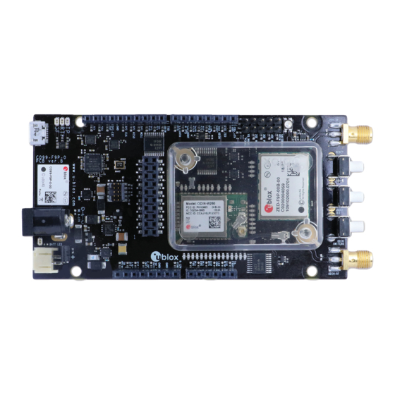
Page 9: C099-F9P Description
C099-F9P description 3.1 Component overview The C099-F9P houses the ZED-F9P RTK high precision positioning module and an ODIN-W2 module for wireless short-range communications. An FTDI component provides dedicated COM port connections with the ZED-F9P and ODIN-W2 via a USB connector. - Page 10 C099-F9P - User guide GNSS antenna connector Wi-Fi/Bluetooth antenna connector ZED-F9P multi band GNSS RTK module ODIN-W2 multi-radio module J2, J3, J8, J9 Arduino Uno connectors DC power jack Battery connector USB (ZED-F9P USB and UART, ODIN-W2 UART ports) Figure 5: Main components and USB ports...
-
Page 11: Zed-F9P Status Leds
C099-F9P - User guide ZED-F9P and ODIN-W2 reset button ZED-F9P safeboot button ODIN-W2 switch 0 interrupt button ODIN-W2 activity LED ODIN-W2 safeboot pins GNSS LEDs: TP, RTK, Geofence Battery charger LED Battery incorrect polarity indicator Figure 6: Switches and LEDs ☞... -
Page 12: Odin-W2 Activity Led
ODIN-W2 in safeboot mode LED off the safeboot jumper to be connected. Table 1: ODIN-W2 Mbed FW LED activity states and colors ODIN-W2 activity LED Figure 8: ODIN-W2 activity LED position on C099-F9P board UBX-18063024 - R11 C099-F9P description Page 12 of 41... -
Page 13: Using The C099-F9P
C099-F9P - User guide Using the C099-F9P The ZED-F9P is shipped with the latest HPG firmware. Check the latest ODIN-W2 Mbed FW availability and information on the FW update procedures in section 7 Firmware update. 4.1 Powering the board The board can be powered from a variety of sources: ... -
Page 14: Non-Wireless Operation
4.2 GNSS RF input The C099-F9P board should be used with the antenna supplied with the kit. If another active antenna is used, be aware that the RF input has a bias output designed to supply 3.3 V DC with a 70 mA maximum current load. -
Page 15: User Interfaces
Figure 13: The supplied GNSS multi-band antenna 4.3 User interfaces The C099-F9P has a number of fixed connection options besides the wireless modes. There is also an additional Arduino R3 / Uno interface for external host connection. The USB connector on the board provides connection via an on-board hub providing: ... -
Page 16: Command Line Interface Of Odin-W2
C099-F9P - User guide Figure 15: u-center view with ZED-F9P connected Additional UBX protocol messages can be enabled to view additional information in u-center. For example, the following are typical messages the user can poll or enable for periodic update. -
Page 17: Persistent Odin-W2 Settings
C099-F9P - User guide Figure 16: CLI help command Figure 17: Example RPC syntax By typing the help command as in Figure 16, the ODIN-W2 will display all available user commands with a short description. The CLI embodies character echo with limited text edit functions. Misspelled commands are replied to with a list of supported commands. -
Page 18: Rover Operation Using Ntrip
A suitable host is a PC with internet access. A host runs an NTRIP client and streams RTCM corrections to the C099-F9P through a UART or Bluetooth connection. Messages transmitted through a Bluetooth or Wi-Fi link are forwarded to I2C bus and vice versa. The user is advised to enable desired messages in both UART and I2C interfaces in ZED-F9P. -
Page 19: Mobile Hosting
5.2 Mobile hosting A portable rover option is offered by an Android application which utilizes Bluetooth connection to a single C099-F9P. An example application is provided by Lefebure and it is available from Google Play Store: https://play.google.com/store/apps/details?id=com.lefebure.ntripclient. The application integrates an NTRIP client which forwards corrections received from a cellular or a wireless network to Bluetooth interface. -
Page 20: Wireless Communication
RSSI values. To ensure sufficient radio link quality, check that the RSSI level of the host device is well above -80 dBm. Weak signal levels can result in connection losses and limited range. Once the host device has been found by the C099-F9P, the following command starts the pairing process: /bt_bond/run <MAC address>... -
Page 21: Bluetooth Serial Port
COM port. Note that you can ignore the baud rate of the Bluetooth serial port at the host PC. Client SPP connection In order to use the outgoing port (client port) at the host PC, set the C099-F9P in server mode by issuing the following command:... -
Page 22: Wi-Fi Connectivity
Wi-Fi access point and UDP server The C099-F9P RTK base can be set to operate as a Wi-Fi access point and UDP server to deliver RTCM corrections via a Wi-Fi link. For rover operation, the C099-F9P can be configured either to Wi-Fi STA or Wi-Fi AP mode. - Page 23 6.3.1.2 Rover operation in Wi-Fi AP mode In order to connect to a C099-F9P rover via a Wi-Fi link, follow the configuration steps below: 1. Configure the C099-F9P to Wi-Fi AP mode by using the CLI command in terminal: /mem_store/run wifi_ap 2.
-
Page 24: Host Udp Client
Typically the Wi-Fi STA mode is applicable when two C099-F9Ps (base and rover) interconnect via a Wi-Fi link. Firstly, it is recommended to configure the base as instructed in section 6.3.1.1 Base operation in Wi-Fi AP mode. Secondly, the rover C099-F9P is set up to function in Wi-Fi STA and rover mode: 1. -
Page 25: Link Loss
(yellow LED). If the disconnection is not intended, check the Wi-Fi interface at the host PC. Wi-Fi channel congestion can be avoided by changing the Wi-Fi AP channel on C099-F9P. Typically, channel congestion is experienced when the Wi-Fi connection indicators (e.g. LEDs) are OK but no data is received. -
Page 26: Firmware Update
7.1 ZED-F9P firmware update This section shows how to update the firmware and re-enable the configuration settings required for the C099-F9P. The user has two possible serial communication channels to update ZED-F9P: UART1 and USB2.0 ports. To update the ZED-F9P, connect to u-center via USB to the COM port identified as the ZED-F9P and poll MON-VER to view the installed firmware: see Figure 14 for the Device Manager COM port view. - Page 27 C099-F9P - User guide Figure 30: Selecting u-center Firmware image folder At the top is the Firmware image file selection window. Click on the button on the right of the window. This allows you to select the folder and file. Select the new firmware image bin file.
- Page 28 C099-F9P - User guide Figure 33: Click GO for firmware update The firmware update progress indication is shown adjacent to the input window. When programming is complete, the module will start up in a default configuration in which the ZED- F9P serial port is set to 38400 baud.
-
Page 29: Odin-W2 Firmware Update
Prior to firmware upload, the ODIN-W2 must be started in safeboot mode. Proceed by placing a safeboot jumper and reboot C099-F9P. Location of the safeboot pin header and the reset button is depicted in Figure 6. To confirm the ODIN-W2 started in safeboot mode the ODIN-W2 activity LED remains off. - Page 30 .\stm32flash.exe -b 115200 -w <ODIN-W26X-SW.bin> -S 0x8010000 COM<port number> Instructions of connectivity configurations of ODIN-W2 running the u-connectXpress SW are available in C099-F9P User guide [5]. Figure 36: Power shell capture of bootloader upload Figure 37: Power shell capture of u-connectXpresssoftware upload UBX-18063024 - R11...
-
Page 31: Arduino Header Connections
3.3 V compliant. J9, Arduino D J3, Arduino B J8, Arduino C J2, Arduino A Figure 38: C099-F9P Arduino connectors Figure 39: C099-F9P Arduino R3 connections UBX-18063024 - R11 Arduino header connections Page 31 of 41... -
Page 32: Appendix
Table 4: Wi-Fi/Bluetooth antenna ☞ The variant included in the the C099-F9P kit is with an SMA connector and has to be mounted on the corresponding antenna connector of the C099-F9P board if you wish to use Wi-Fi or Bluetooth connectivity. -
Page 33: D Mechanical Board Dimensions
C099-F9P - User guide D Mechanical board dimensions Figure 40: C099-F9P rev. E dimensions UBX-18063024 - R11 Appendix Page 33 of 41... -
Page 34: E C099-F9P Schematics
C099-F9P - User guide E C099-F9P schematics The following pages show the complete schematic for the C099-F9P evaluation board. UBX-18063024 - R11 Appendix Page 34 of 41... - Page 35 C099-F9P - User guide UBX-18063024 - R11 Appendix Page 35 of 41...
- Page 36 C099-F9P - User guide UBX-18063024 - R11 Appendix Page 36 of 41...
- Page 37 C099-F9P - User guide UBX-18063024 - R11 Appendix Page 37 of 41...
- Page 38 C099-F9P - User guide UBX-18063024 - R11 Appendix Page 38 of 41...
- Page 39 C099-F9P - User guide UBX-18063024 - R11 Appendix Page 39 of 41...
-
Page 40: Related Documents
Name Comments 10-Jul-2018 ghun/byou Initial release 19-Oct-2018 byou Updates for the C099-F9P rev. B board revision. 8-Nov-2018 olep Updates for Mbed3 FW in ODIN-W2 1-Feb-2019 olep Updates for Wi-Fi and NVDS features in ODIN-W2 Updated Arduino J9 schematics. Polarity requirement of the battery... -
Page 41: Contact
C099-F9P - User guide Contact For complete contact information, visit us at www.u-blox.com. u-blox Offices North, Central and South America Headquarters Asia, Australia, Pacific Europe, Middle East, Africa u-blox America, Inc. u-blox Singapore Pte. Ltd. u-blox AG Phone: +1 703 483 3180...
Need help?
Do you have a question about the C099-F9P and is the answer not in the manual?
Questions and answers