
Related Manuals for LFA Tablet Presses TDP 5

Summary of Contents for LFA Tablet Presses TDP 5
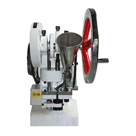
- Page 1 TDP 5® Tablet Press User Manual We don’t just sell machines— we provide service.
-
Page 2: Copyright Notice
Copyright Notice © LFA Machines Oxford Limited, published in 2019 by LFA Machines Oxford Limited 2019. Registered in England and Wales, company number 08428898, registered office for service Demar House 14 Church Road East Wittering, Chichester, West Sussex, PO20 8PS. All rights reserved. -
Page 3: Important Safety Information
• Use this machine only for its intended use For personal protection while transporting the as described in this manual. TDP 5®, abide by these actions: • Turn off and unplug the machine before • Use an engine hoist to lift the machine. -
Page 4: Important Safety Information
Modes for Stopping In the case of an emergency during manual operation, immediately stop turning the Hand Wheel and remove yourself from the TDP 5®. In the case of an emergency during motor operation, immediately press the red OFF button (see... -
Page 5: Table Of Contents
Important Safety Information Intended Use Personal Protection General Hazards Important Safety Information Symbols Modes for Stopping TDP 5 Components TDP 5 Parts List Preface Training On-Site/Off-Site Training Training via Video Chat/Phone LFA Articles LFA Videos Installation Tools and Materials Needed... - Page 6 Table of Contents - Continued Common Tablet Issues De-Jamming the TDP 5 Cleaning Storing the TDP 5 Appendix Glossary Description of TDP 5 Parts Food Grade Point of Contact Parts Technical Specifications Maintenance Checklist Diagrams Resources...
-
Page 7: Tdp 5 Components
TDP 5 Components... -
Page 8: Tdp 5 Parts List
TDP 5® Parts List 1. TDP 5® Base (#AEC0000) 2. Lower Drift Pin Assembly Cogs (#AEC0012) 3. Lower Drift Pin Assembly Locking Bar (#AEC0013) 4. Lower Drift Pin Assembly Lifting Bar (#AEC0034) 5. Lower Drift Pin Assembly (#AEC0011) 6. Boot Bolt and Spring (inside Boot) (#AEC0051; #AEC0055) 7. -
Page 9: Preface
Preface The TDP 5® Tablet Press has the ability to press small quantities of tablets in a wide variety of sizes from a powder formulated with dry granular materials and an excipient. By generating up to 50 kN of pressure with either electrical or manual power, the TDP 5® can produce up to 4,800 tablets an hour with interchangeable dies. -
Page 10: Training
LFA writes informative articles about desktop tablet presses, which includes instructions, procedures, and guides. To access the articles, go to https://www.lfatabletpresses.com/articles LFA Videos LFA has created several videos involving the TDP 5® and other desktop tablet presses. To access the videos, go to https://www.lfatabletpresses.com/videos https://www.youtube.com/channel/... -
Page 11: Installation
Installation Tools and Materials Needed Before you install and operate the TDP 5®, it is best to have the following tools and materials on hand for general operation and maintenance: • Engine hoist or lift and lifting strap • Mounting materials such as: •... - Page 12 The shipping crate will contain the following: 1. The assembled TDP 5® 2. The Tooling (already installed) 3. The Hopper 4. The De-Jamming Bar Note: The Hand Wheel Handle is packaged with the De-Jamming Bar.
- Page 13 1.1 Note: Hammer the clips even further down to aid in removing the shipping container from the base. 2. Lift the top of the shipping container from its base, which is bolted to the TDP 5®. 3. Remove the plastic wrapping and set the Hopper aside.
-
Page 14: Assembly
Assembly The TDP 5® comes almost fully assembled. Insert the Hopper into the Boot like so:... - Page 15 • Engine hoist and lifting strap Instructions 1. Secure the engine hoist onto the eyelet bolt attached to the top of the TDP 5® Base. 2. Wrap the lifting strap to support both the bottom and top of the TDP 5®.
- Page 16 TDP 5®. There are other options as well that can prevent the TDP 5® from moving, which are described below: Non-Slip Pad Placing a pad or mat that grips the surface underneath the TDP 5®...
-
Page 17: Manual And Electrical Controls
Manual and Electrical Controls Basic Components A description of the principal components follows: • The Hand Wheel can be turned to start the cam track's direction. • The Top Cam guides the punches’ movement. • The Hopper holds the dry materials that will be compressed. •... - Page 18 TDP 5® Process The basic mechanism of the TDP 5® involves filling the Tooling (Die, Upper Punch, and Lower Punch) with powder, compressing the powder, and ejecting the tablet. Filling the Tooling with Powder The dry materials are poured into the Hopper, which funnels the powder into the Boot. As the Hand Wheel is manually operated, the Top Cam withdraws the Upper Punch from the Die and moves up the Lower Punch to the Die.
- Page 19 2.1 Note: Always manually operate the TDP 5® for one rotation to ensure that it is operating correctly. 3. Plug in the TDP 5® to an electrical outlet. 4. Press the green button (O) to start the TDP 5 and the red button (—) to turn off the TDP 5®.
-
Page 20: Settings And Adjustment
Settings and Adjustment The TDP 5®’s settings can be adjusted. Tuning the Tooling can help with changing the tablets’ characteristics and how they are ejected from the machine. Ejection Height When the Upper Punch is fully lifted, the Lower Punch in its highest position should be flush with the Die: If the Lower Punch is above or below the Die’s face, it will affect how smoothly the tablet is ejected. - Page 21 5. Run an ungloved finger over the Base Plate to ensure the Die is flush. 6. Secure the bolt in the Lower Drift Pin 7. Reattach the Ejection Tray to the TDP 5®. Assembly Locking Bar with an Allen key.
- Page 22 Note: Wear latex/rubber gloves (and appropriate food grade attire if applicable) during this process. WARNING: To prevent any potential personal injury, unplug the TDP 5® from the electrical outlet. 1. Produce a test tablet to determine how the Tooling should be adjusted.
- Page 23 5.1 Note: Ensure that the Lower Drift Pin turn counterclockwise. To decrease the Assembly Locking Bar is situated tablet weight, turn clockwise. vertically. 6. Produce a test tablet to make sure the weight is correct. 7. Reattach the Ejection Tray to the TDP 5®.
- Page 24 • Hairnet and/or beard net (food grade products only) • Sterile shoe covers (food grade products only) WARNING: To prevent any potential personal injury, unplug the TDP 5® from the electrical outlet. CAUTION: Overtightening can damage the Tooling and/or Boot.
- Page 25 4. Turn the Hand Wheel until the Upper Punch is raised. 5. Loosen the Upper Drift Pin Assembly Locking Nut with a wrench while keeping the Upper Drift Pin Assembly in place with another wrench.
- Page 26 6. Turn the Hand Wheel until the Upper Drift Pin Assembly is exposed. 7. Rotate the Upper Drift Pin Assembly with a wrench or by hand. 7.1 Note: To increase the pressure and harden the tablet, turn clockwise. To decrease the pressure and soften the tablet, turn counterclockwise.
-
Page 27: Maintenance
Maintenance To ensure that the TDP 5® will have a long operational life, maintenance is essential. This section includes methods for replacing parts, troubleshooting solutions, and how often to grease and clean your machines to keep its performance optimal. General Maintenance Prescriptions •... - Page 28 1. Rub a finger’s worth of grease on the Boot Timing Cam’s side. 1.1 Note: Be sure to lubricate the Boot Timing Cam Runner. 2. Lubricate the Eccentric Sheave Strap's Grease Nipple with the grease gun. 2.1 Note: Rotate the Hand Wheel during this to ensure grease gets in between the Eccentric Sheave and the Eccentric Sheave Strap.
- Page 29 4. Lubricate the Grease Nipple nearest to the Boot Timing Cam. 5. Lubricate the Pinion Gear.
- Page 30 Lubrication Schedule LFA recommends the following TDP 5® parts to be lubricated according to the following frequency: Part Location Image Frequency Type of Lubricant The heads of the Visually inspect and Tooling heads Upper Punch and Assembly paste apply when dry...
-
Page 31: Dismantling For Repair And Replacement
Dismantling for Repair and Replacement Eventually due to wear and tear, some parts of the TDP 5® will need to be removed for repair and replacement. To prevent any delays in your tablet production, it is best practice to keep extra parts just in case. -
Page 32: Tooling
Die you currently have is damaged, it is necessary to change the Tooling. To buy new Tooling from LFA, simply go to https://www.lfatabletpresses.com/products/tablet- press-tooling To watch a video of a TDP 5® Tooling change, go to https://www.lfatabletpresses.com/videos/how- to-change-tdp-punch-die-tooling Tools and Materials Needed •... - Page 33 3. Loosen the Boot’s set screw with an Allen key. 4. Remove the Boot Bolt and Spring underneath the Boot with an Allen key. 5. Take off the Boot carefully and remove any powder still inside it. 6. Loosen the bolts underneath the Base Plate with an Allen key.
- Page 34 7. Turn the Hand Wheel until the Upper Drift Pin Assembly is lowered. 8. Loosen the Upper Punch Die Locking Nut with a wrench while keeping the Upper Punch Drift Assembly in place with another wrench. 9. Remove the Upper Punch by hand. 9.1 Note: If you cannot remove by hand, carefully use grippers or pliers.
- Page 35 13. Remove the bolt that locks the Lower Punch with an Allen key. 14. Remove the Lower Punch by hand. 14.1 Note: If you cannot remove by hand, carefully use grippers or pliers. Note: To help ensure that the Die is inserted correctly, LFA recommends using an Insertion Ring.
- Page 36 17. Place the Base Plate onto the TDP 5® Base. 18. Insert the new Die into the middle of the Base Plate. 19. Reinsert the set screw that locks the Die with an Allen key. 19.1 Note: Make sure the set screw is not fully tightened.
- Page 37 22. Reinsert the Base Plate's bolts. 22.1 Note: The Die's set screw can be fully tightened now. 23. Position the Boot back on the Base Plate. 24. Insert the Boot Timing Bar's end in the Boot 25. Resecure the Boot Bolt and Spring underneath the Boot with an Allen key. 26.
-
Page 38: Boot Timing Bar
Boot Timing Bar This part can become warped from collision, and it is critical to the TDP 5®’s operation. If you need to replace your TDP 5®’s Boot Timing Bar, the process is quite simple. Tools and Materials Needed • Set of metric Allen keys with ball ends •... - Page 39 5. Remove the top part of Boot Timing Bar from the Boot Timing Cam. 5.1 Note: To make removal easier, turn the Handle to rotate the Boot Timing Cam so you can easily access the Boot Timing Bar. 6. Remove the Boot Timing Cam Runner from the Boot Timing Bar by hand. 7.
- Page 40 10. Insert the new Boot Timing Bar's end in the Boot 11. Tighten the Boot Timing Bar bolt with an Allen key. 12. Tighten the Boot Timing Bar bolt's nuts with a wrench. 13. Reinsert the Hopper. 14. Turn the Hand Wheel for one rotation to ensure that the machine runs smoothly before plugging it in and turning it on.
-
Page 41: Boot
Boot Due to its constant movement, the Boot can wear down and prevent granular material from flowing smoothly. Replacing this part is a simple process. To watch a video of Boot removal, go to https:// www.lfatabletpresses.com/videos/how-to-remove-the-boot-timing-bar-on-a-tdp-5 Tools and Materials Needed •... - Page 42 4. Remove the Boot Bolt and Spring underneath the Boot with an Allen key. 5. Take off the Boot carefully and remove any powder still inside it. Replace the Boot 6. Position the new Boot on the Base Plate. 7. Insert the Boot Timing Bar's end in the new Boot 8.
-
Page 43: Upper Drift Pin Assembly
Upper Drift Pin Assembly The Upper Drift Pin Assembly holds the TDP 5®’s Upper Punch. Sometimes this part threads or bends, which interferes with smooth movement. Tools and Materials Needed • Set of metric Allen keys with ball ends • 24 mm wrenches (2) •... - Page 44 3. Loosen the Boot’s set screw with an Allen key. 4. Remove the Boot Bolt and Spring underneath the Boot with an Allen key. 5. Take off the Boot carefully and remove any powder still inside it. 6. Loosen the bolts underneath the Base Plate with an Allen key. 7.
- Page 45 9. Remove the Upper Punch by hand. 9.1 Note: If you cannot remove by hand, carefully use grippers or pliers. 10. Remove the Base Plate with the Die still inside it. 11. Remove the bolt that locks the Die with an Allen key. 12.
- Page 46 13. Remove the bolt that locks the Lower Punch with an Allen key. 14. Remove the Lower Punch by hand. 15. Loosen the Upper Drift Pin Assembly Locking Nut with a wrench. 16. Unscrew the Upper Drift Pin Assembly from the Upper Drift Pin Assembly Threaded Cam.
- Page 47 Replace the Upper Drift Pin Assembly 17. Screw in the new Upper Drift Pin Assembly onto the Upper Drift Pin Assembly Threaded Cam. 18. Tighten the Upper Drift Pin Assembly Locking Nut onto the Upper Drift Pin Assembly Threaded Cam by hand or with a wrench.
- Page 48 20. Reinsert the bolt that locks the Lower Punch with an Allen key. 20.1 Note: Make sure that the Lower Punch's “keyed” section is facing forward. 21. Place the Base Plate onto the TDP 5® Base. 22. Insert the Die into the middle of the Base Plate.
- Page 49 24. Insert the Upper Punch into the Upper Drift Pin Assembly. 25. Tighten the Upper Punch Die Locking Nut onto the Upper Drift Pin Assembly with a wrench. 25.1 Note: Rotate the Hand Wheel to see that the Upper Punch smoothly enters the Die bore and that the Die is seated firmly in the Upper Drift Pin Assembly.
-
Page 50: Upper Drift Pin Assembly Threaded Cam
Upper Drift Pin Assembly Threaded Cam This part connects the Eccentric Sheave Strap and the Upper Drift Pin Assembly. It can become threaded or warped in the case of accidental collision and can be easily removed and replaced. Tools and Materials Needed •... - Page 51 4. Loosen the Boot’s set screw with an Allen key. 5. Remove the Boot Bolt and Spring underneath the Boot with an Allen key. 6. Take off the Boot carefully and remove any powder still inside it. 7. Loosen the bolts underneath the Base Plate with an Allen key. 8.
- Page 52 10. Remove the Upper Punch by hand. 10.1 Note: If you cannot remove by hand, carefully use grippers or pliers. 11. Remove the Base Plate with the Die still inside it. 12. Remove the bolt that locks the Die with an Allen key. 13.
- Page 53 14. Remove the bolt that locks the Lower Punch with an Allen key. 15. Remove the Lower Punch by hand. 16 Loosen the Upper Drift Pin Assembly Locking Nut with a wrench. 17. Unscrew the Upper Drift Pin Assembly from the Upper Drift Pin Assembly Threaded Cam. 18.
- Page 54 20. Remove the Upper Drift Pin Assembly Threaded Cam from the Eccentric Sheave Strap. Replace the Upper Drift Pin Assembly Threaded Cam 21. Reinsert the Upper Drift Pin Assembly Threaded Cam's pin and secure it with a circlip. 22. Tighten the Upper Drift Pin Assembly Locking Nut onto the new Upper Drift Pin Assembly Threaded Cam by hand or with a wrench.
- Page 55 25. Reinsert the bolt that locks the Lower Punch with an Allen key. 25.1 Note: Make sure that the Lower Punch's “keyed” section is facing forward. 26. Place the Base Plate onto the TDP 5® Base. 27. Insert the Die into the middle of the Base Plate.
- Page 56 29. Insert the Upper Punch into the Upper Drift Pin Assembly. 30. Tighten the Upper Punch Die Locking Nut onto the Upper Drift Pin Assembly with a wrench. 30.1 Note: Rotate the Hand Wheel to see that the Upper Punch smoothly enters the Die bore and that the Die is seated firmly in the Upper Drift Pin Assembly.
-
Page 57: Lower Drift Pin Assembly
Lower Drift Pin Assembly The Lower Drift Pin Assembly may need to be removed if any pins become stuck inside it and/or the Lower Drift Pin Assembly Cogs become jammed on it. Tools and Materials Needed • Set of metric Allen keys with ball ends •... - Page 58 3. Loosen the Boot’s set screw with an Allen key. 4. Remove the Boot Bolt and Spring underneath the Boot with an Allen key. 5. Take off the Boot carefully and remove any powder still inside it. 6. Loosen the bolts underneath the Base Plate with an Allen key. 7.
- Page 59 10. Remove the bolt that locks the Lower Punch with an Allen key. 11. Remove the Lower Punch by hand. 11.1 Note: If you cannot remove by hand, carefully use grippers or pliers. 12. Remove the Lower Drift Pin Assembly Locking Bar with an Allen key. 13.
- Page 60 14. Remove the bolts from the Upper Drift Pin Assembly Mounting Block with an Allen key. 15. Take off the Upper Drift Pin Assembly Mounting Block and remove the Lower Drift Pin Assembly. Replace the Lower Drift Pin Assembly 16. Insert the new Lower Drift Pin Assembly into the Base and Upper Drift Pin Assembly Mounting Block.
- Page 61 18. Rotate one of the Lower Drift Pin Assembly Cogs onto the new Lower Drift Pin Assembly. 19. Raise the Lower Drift Pin Assembly Cog just below the bolt bore on the Lower Drift Pin Assembly.
- Page 62 20. Rotate the remaining Lower Drift Pin Assembly Cog onto the Lower Drift Pin Assembly below the Lower Drift Pin Assembly Timing Bar. 21. Rescrew the bolt into the Lower Drift Pin Assembly Locking Bar with an Allen key. 21.1 Note: Ensure that the Lower Drift Pin Assembly Locking Bar is situated vertically.
- Page 63 23. Reinsert the bolt that locks the Lower Punch with an Allen key. 23.1 Note: Make sure that the Lower Punch's “keyed” section is facing forward. 24. Place the Base Plate onto the TDP 5® Base. 25. Reinsert the Die into the middle of the Base Plate.
- Page 64 27. Reinsert the Base Plate's bolts. 28. Position the Boot back on the Base Plate. 29. Insert the Boot Timing Bar's end in the Boot 30. Resecure the Boot Bolt and Spring underneath the Boot with an Allen key. 31. Tighten the Boot’s set screw with an Allen key. 32.
-
Page 65: Lower Drift Pin Assembly Timing Rod Runner Bolt
Lower Drift Pin Assembly Timing Rod Runner Bolt The Lower Drift Pin Assembly Timing Rod's Runner Bolt can be damaged due to overtightening and/or being under too much pressure. Tools and Materials Needed • Set of metric Allen keys with ball ends •... - Page 66 3. Loosen the two nuts on the Lower Drift Pin Assembly Timing Rod with a wrench. 4. Rotate the Lower Drift Pin Assembly Timing Rod until its runner bolt is accessible. 4.1 Note: If the Lower Drift Pin Assembly Timing Rod is difficult to move, move the Electrical Drive Flywheel and Cam Drive Cog to make more space.
- Page 67 10. Re-tighten the two nuts on the Lower Drift Pin Assembly Timing Rod with a wrench. 10.1 Note: Make sure that the Lower Drift Pin Assembly is fully down and adjust the two nuts until the Lower Drift Pin Assembly Lifting Bar is perfectly level and resting on the fill depth adjustment cog.
-
Page 68: Belt
1. Adjust the nuts on the Motor Support Arm with a 19 mm wrench to loosen the V Belt. 1.1 Note: The closer the Motor Mounting Plate is to the TDP 5®, the looser the V Belt’s slack will be. - Page 69 4. Adjust the nut on on the Motor Support Arm to tighten the V Belt. 4.1 Note: The further away the Motor Mounting Plate is from the TDP 5®, the tighter the V Belt’s slack will be. The correct tension for a new V Belt is [N] 141.64.
-
Page 70: Hand Wheel
• Disposable latex/rubber gloves (for food grade products and to protect hands from grease) • Hairnet and/or beard net (food grade products only) • Sterile shoe covers (food grade products only) WARNING: To prevent any potential personal injury, ALWAYS unplug the TDP 5 from the electrical outlet when replacing parts. Instructions Note: Wear latex/rubber gloves (and appropriate food grade attire if applicable) during this process. -
Page 71: Electrical Drive Flywheel
1. Adjust the nuts on the Motor Support Arm with a 19 mm wrench to loosen the V Belt. 1.1 Note: The closer the Motor Mounting Plate is to the TDP 5®, the looser the V Belt’s slack will be. - Page 72 3. Remove the Rear Enclosure Plate off of the back of the TDP 5® with an Allen key. 4. Loosen the nut from the Pinion Gear Cam that connects the Pinion Gear and the Electrical Drive Flywheel to the TDP 5 Base® with a 30 mm wrench.
- Page 73 10. Adjust the nuts on the Motor Support Arm to tighten the V Belt. 10.1 Note: The further away the mount is from the TDP 5®, the tighter the V Belt’s slack will be. The correct tension for the V Belt is [N] 94.42.
-
Page 74: Boot Timing Cam
Boot Timing Cam Although this part lasts long, it can become worn over time. To replace the Boot Timing Cam, the Hand Wheel must be removed first. Tools and Materials Needed • Heavy rubber mallet • Set of metric Allen keys with ball ends •... - Page 75 4. Loosen the Boot Timing Bar bolt's nuts with a wrench. 5. Loosen the Boot Timing Bar bolt with an Allen key. 6. Remove the Boot Timing Bar's end from the Boot. 7. Gently hit the Boot Timing Cam with a rubber mallet to disengage it from the engraved key on the Top Cam.
- Page 76 Replace the Boot Timing Cam 8. Position the new Boot Timing Cam into the engraved key on the Top Cam. 9. Place the Boot Timing Cam Runner on the Boot Timing Bar. 10. Insert the Boot Timing Bar with the runner into the side of the Boot Timing Cam. 11.
- Page 77 18. Reinsert the Hopper. 19. Turn the Hand Wheel for one rotation to ensure that the machine runs smoothly before plugging it in and turning it on.
-
Page 78: Pinion Gear
1. Adjust the nuts on the Motor Support Arm with a 19 mm wrench to loosen the V Belt. 1.1 Note: The closer the Motor Mounting Plate is to the TDP 5®, the looser the V Belt’s slack will be. - Page 79 3. Remove the Rear Enclosure Plate from the back of the TDP 5® with an Allen key. 4. Loosen the nut from the Pinion Gear Cam that connects the Pinion Gear and the Electrical Drive Flywheel to the TDP 5® Base with a 30 mm wrench.
- Page 80 6. Insert the new Pinion Gear and the Pinion Gear Cam into the Electrical Drive Flywheel. 7. Install the new Pinion Gear, the Pinion Gear Cam, and the Electrical Drive Flywheel into the TDP 5® Base. 8. Reattach the Rear Enclosure Plate to the back of the TDP 5® with an Allen key.
- Page 81 10. Adjust the nuts on the Motor Support Arm to tighten the V Belt. 10.1 Note: The further away the mount is from the TDP 5®, the tighter the V Belt’s slack will be. The correct tension for the V Belt is [N] 94.42.
-
Page 82: Cam Drive Cog
1. Adjust the nuts on the Motor Support Arm with a 19 mm wrench to loosen the V Belt. 1.1 Note: The closer the Motor Mounting Plate is to the TDP 5®, the looser the V Belt’s slack will be. - Page 83 3. Remove the Rear Enclosure Plate from the back of the TDP 5® with an Allen key. 4. Loosen the nut from the Pinion Gear Cam that connects the Pinion Gear and the Electrical Drive Flywheel to the TDP 5® Base with a 30 mm wrench.
- Page 84 Remove the Cam Drive Cog 6. Remove the Cam Drive Cog Safety Cover with an Allen key. 7. Remove the Cam Drive Cog Cap from the Cam Drive Cog with an Allen key. 8. Disengage the Cam Drive Cog from the engraved key on the Top Cam. 7.
- Page 85 13. Install the Pinion Gear, the Pinion Gear Cam, and the Electrical Drive Flywheel into the TDP 5® Base. 14. Reattach the Rear Enclosure Plate to the back of the TDP 5® with an Allen key. 15. Place the V Belt back onto the Drive Belt Pulley and the Electrical Drive Flywheel.
- Page 86 16. Adjust the nuts on the Motor Support Arm to tighten the V Belt. 16.1 Note: The further away the mount is from the TDP 5®, the tighter the V Belt’s slack will be. The correct tension for the V Belt is [N] 94.42.
-
Page 87: Drive Belt Pulley
1. Adjust the nuts on the Motor Support Arm with a 19 mm wrench to loosen the V Belt. 1.1 Note: The closer the Motor Mounting Plate is to the TDP 5®, the looser the V Belt’s slack will be. - Page 88 6. Adjust the nuts on the Motor Support Arm to tighten the V Belt. 6.1 Note: The further away the Motor Mounting Plate is from the TDP 5®, the tighter the V Belt’s slack will be. The correct tension for the V Belt is [N] 94.42.
-
Page 89: Motor
Turn off and unplug the machine before replacing this part. The TDP 5® motor is quite heavy. Be sure to have a firm hold on this part while you are removing the connecting bolts to prevent it from falling and possibly causing personal injury. - Page 90 6. Remove the Electrical Box's wires from the Motor with a crosshead screwdriver to free the Motor from the TDP 5®. 6.1 Note: if the wiring in your Motor is different, take a picture to use it as a reference later.
- Page 91 Replace the Motor 7. Position the new Motor behind the TDP 5® and the Motor Mounting Plate 8. Insert the four bolts through the Motor Mounting Plate and into the Motor and tighten their nuts with a wrench. 9. Reinsert the Motor Support Arm into the Motor Mounting Plate and loosely tighten its nut with a 19 mm wrench.
- Page 92 14. Adjust the nuts on on the Motor Mounting Plate to tighten the V Belt. 14.1 Note: The further away the Motor Mounting Plate is from the TDP 5®, the tighter Belt’s slack will be. The correct tension for the V Belt is [N] 94.42.
-
Page 93: Top Cam
Top Cam The Top Cam drives many important parts in the TDP 5®'s upper assembly. These instructions explain how to remove and replace the Top Cam, which involves the removal and replacement of all the other parts driven by it. - Page 94 Cam. 10. Gently tap the copper pipe against the Top Cam with a rubber mallet to move it through the TDP 5's Base. 11. Continue to tap the Top Cam with the copper pipe and rubber mallet until the Eccentric Sheave and Eccentric Sheave Strap disengage.
- Page 95 12. Disengage the Boot Timing Cam from the Top Cam's engraved key. 12.1 Note: Use a rubber mallet if the Boot Timing Cam is difficult to remove. 13. Keep tapping the Top Cam until it goes completely through the TDP 5®'s Base.
- Page 96 Replace the Top Cam 14. Gently begin to tap the new Top Cam through the TDP 5® Base and the Eccentric Sheave and Eccentric Sheave Strap. 15. Continue to tap the Top Cam until it is completely through the TDP 5® Base.
- Page 97 21. Insert the Hand Wheel on the new Top Cam's engraved key. 22 Tighten the Hand Wheel Cap's bolt with an Allen key. 23. Reattach the Ejection Tray with an Allen key. 24. Reinsert the Hopper carefully and catch any powder still inside of it.
-
Page 98: Troubleshooting
Troubleshooting Sometimes unavoidable issues will occur while operating the TDP 5®. Fortunately, there are several methods to remedy these issues. Common Machine/Part Issues Symptom Possible Cause Possible Solution Regularly oil and grease all the Grease point areas are dry. Grease Nipple points. - Page 99 Symptom Possible Cause Possible Solution Boot is blocked and not enough Check the Boot for a potential clog. materials are flowing out. Tighten the Boot Timing Bar's nuts The Boot Timing Bar is not secured. and bolt. Rotate the Upper Drift Pin Assembly There is not enough pressure.
-
Page 100: Common Tablet Issues
Common Tablet Issues Symptom Possible Cause Possible Solution Remove the double tablet manually Previous tablet did not eject correctly. from the Die bore. Double tablets Clean the Tooling to remove any Excess granular materials were excess granular materials and make placed in the Die, which prevented sure that it is clean and completely the ejection of the existing tablet. -
Page 101: Jamming The Tdp
De-Jamming the TDP 5® There are several reasons why a TDP 5® might jam such as: • The fill depth is set too low and the pressure is set too high. • There is a build up of powder sticking to the Tooling. - Page 102 2. Loosen the Boot’s set screw with an Allen key. 3. Remove the Boot Bolt and Spring underneath the Boot with an Allen key. 4. Take off the Boot carefully and remove any powder that is inside of it. 5. Insert the De-Jamming Bar into one of the holes on the Electrical Drive Flywheel. 6.
- Page 103 7. Reposition the Boot on the Base Plate correctly and insert the Boot Timing Bar's end in the boot. 8. Resecure the Boot Bolt and Spring underneath the Boot with an Allen key. 9. Tighten the Boot’s set screw with an Allen key. 10.
- Page 104 Method 2: Run a Reverse Rotation Note: Please refer to the Dismantling for Repair and Replacement section for additional assistance. 1. Remove the Hopper carefully and catch any powder that is inside of it. 2. Loosen the Boot’s set screw with an Allen key. 3.
- Page 105 6. Reposition the Boot on the Base Plate correctly and insert the Boot Timing Bar's end in the boot. 7. Resecure the Boot Bolt and Spring underneath the Boot with an Allen key. 8. Tighten the Boot’s set screw with an Allen key. 9.
-
Page 106: Cleaning
During the TDP 5®’s operation, excess powder will find its way into parts of the machine, particularly in the Base, Hopper, Boot, Base Plate, and Tooling. It is important to clean the TDP 5 thoroughly to prevent rusting and cross contamination. To watch a video of a TDP 5® cleaning, go https://www.lfatabletpresses.com/videos/cleaning-your-tdp-5-tablet-press... - Page 107 4. Loosen the Boot’s set screw with an Allen key. 5. Remove the Boot Bolt and Spring underneath the Boot with an Allen key. 6. Take off the Boot carefully and remove any powder still inside it. 7. Loosen the bolts underneath the Base Plate with an Allen key.
- Page 108 8. Turn the Hand Wheel until the Upper Drift Pin Assembly is lowered. 9. Loosen the Upper Punch Die Locking Nut with a wrench while keeping the Upper Punch Drift Assembly in place with another wrench. 10. Remove the Upper Punch by hand. 10.1 Note: If you cannot remove by hand, carefully use grippers or pliers.
- Page 109 Clean the Base 16. Vacuum any powder/debris from the machine. 17. Spray the TDP 5® Base with the cleaner, particularly in the Tooling's location. 18. Rinse the cleaner off with drinking water. 19. Sanitize the TDP 5® Base with a clean cloth.
-
Page 110: Storing The Tdp 5
After its thorough cleaning, the TDP 5® needs to be stored in the proper conditions. It is important to store it in an environment in which the machine is safe from rusting. The TDP 5®’s high traction areas and the Tooling need to be lubricated separately before you store them. - Page 111 4. Lubricate the Cam Drive Cog and Lower Drift Pin Assembly Timing Rod Runner Bolt. 5. Lubricate the Pinion Gear. You can also lubricate any point of traction on the TDP 5 at your own discretion; just be sure not to over-lubricate.
-
Page 112: Appendix
Appendix Glossary Term Definition Any substance or mixture of substances used API/Active Pharmaceutical Ingredient that is an active ingredient in the drug product. See excipient. Binding agent The part of the Tooling that makes up the hole in which the powder is compressed and shaped into a tablet. -
Page 113: Description Of Tdp 5 Parts
Description of TDP 5® Parts TDP Base (#AEC0000) Tooling The TDP Base is the main base for the TDP 5®, The Tooling consists of the Die, the Upper and all working parts are connected to it. It is Punch, and the Lower Punch. This die set important that the TDP Base be fixed onto a compresses the powder into the tablet. - Page 114 Boot Bolt and Spring (#AEC0051; #AEC0055)) Boot (#AEC0036) The Boot Bolt and Spring holds the Boot in place The Boot is where the dry granular materials while the press is running and allows it to move are held for pressing. It fills the Die bore with back and forth.
- Page 115 Eccentric Sheave (#AEC0033) All other TDP 5 parts are connected to the Top The Eccentric Sheave controls the timing of the Cam. As it is turned, all the parts of TDP 5® Upper Drift Pin Assembly. Order at https://www. move. Order at https://www.lfatabletpresses.com/...
- Page 116 Lower Drift Pin Assembly (#AEC0011) Cam Drive Cog (#AEC0050) The Lower Drift Pin Assembly is located below The Cam Drive Cog is attached to the Top Cam the base of the tablet. It holds the Lower Punch and drives the Lower Drift Pin Assembly Timing in place in the Die while the Upper Punch pushes Rod.
- Page 117 Motor (#AEC0042) Lower Drift Pin Assembly Lifting Bar The Motor is mounted at the back of the TDP 5® (#AEC0034) Base and can be either 110 v or 220 v. Order at The Lower Drift Pin Assembly Lifting Bar lifts the https://www.lfatabletpresses.com/tdp5-motor...
- Page 118 Drive Belt Pulley (#AEC0043) Lower Drift Pin Assembly Timing Rod Runner This Drive Belt Pulley fixes on the Motor's keyed (#AEC0016) axel and has grooves that the V Belt fits into. The The Lower Drift Pin Assembly Timing Rod Runner V Belt is also connected to the Electrical Drive is inserted onto the Lower Drift Pin Assembly Flywheel.
- Page 119 TDP 5 Base and prevents dust powder The Motor Mounting Plate is hinged and collecting in the interior. Order at https://www. connects the Motor to the TDP 5® Base. It can lfatabletpresses.com/tdp5-rear-enclosure-plate be moved to adjust the tension of the V Belt. Order at https://www.lfatabletpresses.com/tdp5-...
-
Page 120: Food Grade Point Of Contact Parts
Food Grade Point of Contact Parts Contact Part Material Boot MABS (Terlux HD 2822) plastic Base Plate S45C carbon steel Tooling User specified (Upper Punch, Lower Punch, and Die) Ejection Tray SUS304 stainless steel Hopper Polypropylene (PP) plastic Technical Specifications Number of dies Max production capacity 4800/hour... -
Page 121: Maintenance Checklist
Maintenance Checklist Before Operation □ Visually inspect the tablet press and the parts. □ Ensure all locking nuts are tight. □ Visually inspect grease nipples and regrease where necessary. □ Tune the tablet press by hand to get the tablet size and weight correct. □... -
Page 122: Diagrams
Diagrams TDP 5® Dimensions... - Page 123 TDP 5® Tooling Dimensions 0 . 0 2 16.5 0 . 0 2 +0. 0 30 5 28 +0. 0 22 5 2 5...
- Page 124 TDP 5® Exploding Diagram...
- Page 125 TDP 5® Wiring Diagram...
- Page 126 TDP 5® Wiring Diagram...
- Page 127 TDP 5® Mounting Diagram...
-
Page 128: Resources
Warranty LFA Machines YouTube Channel For information regarding the warranty policy Our YouTube videos provide you an opportunity of the TDP 5® and other LFA products, please to see how to use our tablet presses, common visit https://www.lfatabletpresses.com/warranty troubleshooting tips, and other LFA products such as capsule fillers and mixers. - Page 129 LFA MACHINES Copyright © 2019 by LFA Machines www.lfamachines.com Germany Taiwan United Kingdom United States Business Parc Am Unit 4B 955 N Sylvania Ave 403, Section 2, 2號 Trippelsberg 92 Murdock Road Fort Worth Taiwan Boulevard Düsseldorf Bicester Texas Taichung City Germany Oxfordshire United States...
Need help?
Do you have a question about the TDP 5 and is the answer not in the manual?
Questions and answers