BendPak HD-9ST Installation And Operation Manual
Four-post lift
Hide thumbs
Also See for HD-9ST:
- Installation and operation manual (50 pages) ,
- Service manual (31 pages) ,
- Installation and operation manual (96 pages)
Table of Contents
Advertisement
Installation and Operation Manual
Manual P/N 5900123 — Manual Revision M — February 2020
Models:
• HD-9ST
• HD-9STX
• HD-9
• HD-9XL
• HD-9XW
Designed and engineered by BendPak Inc. in Southern California, USA. Made in China.
⚠
DANGER
HD-9 Four-Post Lift
entire
Read the
product. Failure to follow the instructions and safety precautions in
this manual can result in serious injury or death. Make sure all other
operators also read this manual. Keep the manual near the product
for future reference. By proceeding with installation and operation,
you agree that you fully understand the contents of this manual.
contents of this manual
1645 Lemonwood Dr.
Santa Paula, CA 93060 USA
Toll Free: (800) 253-2363
Tel: (805) 933-9970
bendpak.com
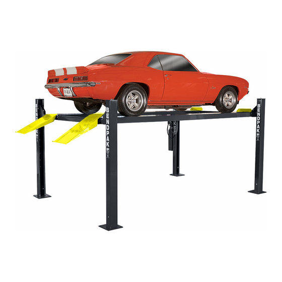
HD-9ST shown.
before
using this
Advertisement
Table of Contents

Related Manuals for BendPak HD-9ST


Summary of Contents for BendPak HD-9ST
- Page 1 Models: • HD-9ST • HD-9STX • HD-9 • HD-9XL • HD-9XW HD-9ST shown. Designed and engineered by BendPak Inc. in Southern California, USA. Made in China. ⚠ entire before Read the contents of this manual using this product. Failure to follow the instructions and safety precautions in DANGER this manual can result in serious injury or death.
- Page 2 Copyright. Copyright © 2020 by BendPak Inc. All rights reserved. You may make copies of this document if you agree that: you will give full attribution to BendPak Inc., you will not make changes to the content, you do not gain any rights to this content, and you will not use the copies for commercial purposes.
-
Page 3: Table Of Contents
Installation Introduction This manual describes the following BendPak Four-Post Lifts: HD-9ST. Four-Post Lift with an overall width of 100.25" (8.4 feet), raising Vehicles up to 9,000 lbs • (4,082 kg). ALI certified. HD-9STX. Has the same overall width as the HD-9ST but with... -
Page 4: Shipping Information
Keep this manual on or near the product for future reference. Read and follow the warnings and instructions on the labels on the product. Contact BendPak at (800) 253-2363 or if you need replacement labels or a techsupport@bendpak.com... - Page 5 BendPak Inc. assumes no liability for damages resulting from: • Use of the equipment for purposes other than those described in this manual. • Modifications to the equipment without prior, written permission from BendPak. • Injury or death caused by modifying, disabling, overriding or removing safety features. •...
-
Page 6: Components
Components The main components of your Lift include: The Power Post can be in either of two • Power Post. The Post that holds the Power Unit. locations . You can tell the Power Post from the other Posts because it has two Mounting Brackets on it. - Page 7 • Plastic Drip Trays. Plastic Drip Trays prevent liquids from falling onto your work area or Vehicle. See the Plastic Drip Trays page on the BendPak website for more information. • Rolling Bridge Jack. A Rolling Bridge Jack raises the wheels of a Vehicle off the Runways of a Lift, making it much easier to perform service such as brake jobs and suspension work while the Vehicle is still on the Lift.
-
Page 8: Specifications
Specifications HD-9 Series Four-Post Lifts P/N 5900123 — Rev. M — February 2020... - Page 9 Model HD-9ST HD-9STX Lifting Capacity 9,000 lbs / 4,082 kg Max capacity at Front Axle 4,500 lbs / 2,041 kg Max capacity at Rear Axle 4,500 lbs / 2,041 kg 5" / 125 mm Min. runway height 70" (5.10 feet) / 1,778 mm 82"...
- Page 10 Model HD-9 HD-9XL HD-9XW Lifting capacity 9,000 lbs / 4,082 kg Max capacity at Front Axle 4,500 lbs / 2,041 kg Max capacity at Rear Axle 4,500 lbs / 2,041 kg 4.5" / 114 mm Min. runway height 82" (6.10 feet) / Maximum rise 70"...
-
Page 11: Faqs
You would need to unbolt the Offside Runway on both ends, slide it over to the other position, and then bolt it into position. adjustable Offside Runway does not apply to the HD-9ST or HD-9STX models Q: Does the Lift have to be anchored in place? -
Page 12: Installation Checklist
Installation Checklist Following are the steps needed to install your Lift. Perform them in the order shown. ☐ 1. Review the safety rules. ☐ 2. Make sure you have the necessary tools. ☐ 3. Plan for Electrical work. ☐ 4. Select the installation location. ☐... -
Page 13: Installation
Only fully trained personnel should be involved in installing this equipment. Pay attention at all times. Use appropriate tools and lifting equipment. Stay clear of moving parts. BendPak recommends referring to the current version of the ANSI/ALI ALIS Standard Safety Requirements for Installation and Service for more information about safely installing, using, and servicing your Lift. - Page 14 Planning for Electrical Work You will need to have a licensed, certified Electrician available at some point in the installation. ⚠ must DANGER All wiring be performed by a licensed, certified Electrician. Notify your Electrician in advance so that they come prepared with an appropriate Power Cord with a Plug for connecting to the power source, a Power Disconnect Switch, and a Thermal Disconnect Switch.
- Page 15 28 days. ⚠ CAUTION BendPak lifts are supplied with installation instructions and Concrete anchors that meet the criteria set by the current version of the American National Standard “Automotive Lifts – Safety Requirements for Construction, Testing, and Validation”, ANSI/ALI ALCTV.
- Page 16 • Non-Slip Rubber Pads. If you do not plan to anchor the Lift (and want to use the optional Caster Kit), you could go to your local hardware store and get non-slip Rubber Pads and size them to fit the bottom of the Base Plates; the Pads will protect against scratches on special flooring if the Lift accidentally shifts as a result of not anchoring the Lift.
- Page 17 Deciding the Lift Orientation Before going any further, decide how you want to orient your Lift. This decision affects where you will place your Power Post and also the positioning of the Runways, which are interchangeable. One Runway has the Hydraulic Cylinder underneath it and is the starting point for the Lifting Cables. The other Runway, called the Offside Runway, does not have anything underneath it.
- Page 18 Creating Chalk Line Guides Create the Chalk Line Guides so that the outside edges of all four Posts fit into the four corners created by the Chalk Line Guides. to determine the Overall Width and Outside Length values for your Lift. Specifications Overall Note:...
- Page 19 To create Chalk Line Guides: 1. Create the Front Chalk Line where you want the Front of the Lift. The Front of the Lift is the end opposite the Drive-up Ramps. Make the Front Chalk Line longer (about 12 inches) than the Overall Width setting. 2.
- Page 20 Unloading and Unpacking Once the components are unloaded, they are your responsibility to move around. As the Lift includes a number of heavy pieces, the closer you unload them to the installation location, the better off you are. ⚠ CAUTION Some Lift components are very heavy;...
- Page 21 Installing the Crosstubes Your Lift has two Crosstubes, both hollow, which allows the Lifting Cables to be run through them to the Posts. The two Crosstubes are: • Crosstube with Large Windows: Goes on the end of the Lift opposite of the Power Post, with the Windows facing the inside.
- Page 22 To install the Crosstubes: 1. Orient the Crosstubes in their required locations. Both Windows must be on the ends of the Powerside Runway and facing the inside of the Lift. 2. Put black Slide Blocks into place on the outside ends of each Gusset (4 Slide Blocks per Gusset, 8 per Crosstube, 16 total for the Lift).
- Page 23 About Safety Locks Safety Locks hold the Runways in place. Once engaged, Safety Locks hold the Runways in place, even if the power goes out or the Hydraulic Hoses break or leak. The Safety Locks are spaced every four inches / 100 mm.
- Page 24 Installing the Ladders and Top Cap Each Post has a Ladder; each Ladder gets installed on the inside back of a Post. Ladders are secured at the top and the bottom. All four Ladders are identical. It is necessary to slide the Ladders in from the very top of the Post. The Top Caps secure the Ladder at the top of each Post and hold the ends of the Lifting Cables.
- Page 25 To install the Ladders and the Top Caps: 1. Take a Ladder and slide it down the back of the Post, with the Bolt Hole end at the bottom. Make sure the Ladder goes through both Slots on each Gusset .
- Page 26 Raising the Crosstubes You need to manually raise the Crosstubes, which makes it easier to complete the rest of the installation tasks. The Crosstubes need to be raised the same height, to the same Safety Lock. To raise the Crosstubes: 1.
- Page 27 Securing the Ladders Because it is much easier to secure the Ladders at the bottom of each Post after the Crosstubes have been raised, that procedure is described here. The following procedure assumes that the Ladders are in place and secured at the top. If this is the case, return to Installing the Ladders and Top Cap.
- Page 28 Removing the Sheaves In order to route the Lifting Cables, you need to remove the Cable Sheaves on the underside of the Powerside Runway and the four Gusset Sheaves and their Lock Pins. keep the components together When you remove the Sheaves, .
- Page 29 Offside Runway: The Offside Runway does not have a Hydraulic Cylinder under it, nor are there the adjustable any Lifting Cables under it. It can be installed in the wide or narrow setting; setting does not apply to the HD-9ST or HD-9STX models Orient the two Runways this way: •...
- Page 30 Use a Forklift or Shop Crane to raise the Runways and move them into position. ⚠ WARNING Pay close attention when moving the Runways into position; they are very heavy and long, and could shift position or fall, potentially causing serious injury. To install the Runways: 1.
- Page 31 Installing the First End of the Flex Tube The Flex Tube is a flexible, black tube that attaches to an opening on the Powerside Runway on one end and to the bottom of the Flex Tube Bracket Plate (near the Power Unit) on the other end. The Flex Tube consolidates and protects three different Cables that come out from under the Powerside Runway on their way to the Power Unit: The Return Line, the Air Line, and Hydraulic Hose.
- Page 32 Before routing the Lifting Cables on your Lift, you need to know the following: • BendPak strongly recommends using protective gloves when working with the Lifting Cables. • Each Lift has four Lifting Cables of varying lengths and can only make one connection.
- Page 33 Threaded end. You have to match the Cable letter with the length. • The four Lifting Cables for the HD-9ST are: o A: 2,926 mm / 9.7 feet / 115.25 inches o B: 4,356 mm / 14.4 feet / 171.5 inches o C: 7,048 mm / 23.2 feet / 277.5 inches...
- Page 34 The following drawing shows the components involved in routing the Lifting Cables. HD-9 Series Four-Post Lifts P/N 5900123 — Rev. M — February 2020...
- Page 35 HD-9 Series Four-Post Lifts P/N 5900123 — Rev. M — February 2020...
- Page 36 Before routing the Cables, extend the Piston on the Hydraulic Cylinder. To extend the Piston: 1. Remove the Shipping Plug from the Return Line Connector. The Return Line Connector is on the Cylinder end closest to where the Power Unit will be. 2.
- Page 37 5. With the Lifting Cable in place, reinstall the Gusset Sheave and the Cable Lock Pin in Post A. 6. Make sure Lifting Cable A is correctly positioned: in between the Gusset Sheave and the Slack under Safety Sheave, with the Cable Lock Pin 7.
- Page 38 Routing Lifting Cables B and D is the same process as routing Lifting Cables A and C, just to the other two Posts and using a different set of Sheaves. Refer to the drawings in the previous section. To route Lifting Cables B and D: Starting with Lifting Cable B , move the entire thing to under the Large Window it goes through, opposite of Cables A and C (already in place).
- Page 39 Working with Compression Fittings and Tubing Your Lift comes with a roll of ¼ inch, black, polyethylene Tubing (also called Poly-Flo® Tubing) that is used with Compression Fittings in two ways: for the Return Line and for the Air Lines. While both lines use Tubing and Compression Fittings, the Return Line and Air Lines Important: are used for completely separate purposes;...
- Page 40 Installing the Air Lines The Air Lines use air pressure to disengage the Safety Locks in each Post so that you can lower the Runways. You will need more of the ¼ inch, black, polyethylene Tubing that came with the Lift and three Air Line Tee Connectors to install the Air Lines.
- Page 41 To install the Air Lines: 1. Find the roll of supplied ¼ inch, black, polyethylene Tubing and three Air Line Tee Connectors. 2. Measure the distances for each of the seven (7) Tubing pieces you will need (see the drawing on the previous page) for the Air Lines.
- Page 42 Installing the Return Line The Return Line takes excess Hydraulic Fluid coming out of the Hydraulic Cylinder and sends it back into the Fluid Reservoir on the Power Unit. The Return Line is a single piece of ¼ inch, black, polyethylene Tubing with Elbow Compression Fittings on each end.
- Page 43 Hydraulic Hoses and Fittings on your Lift, making your new Lift inoperable. Your Lift is shipped with clean components; however, BendPak strongly recommends that you take secondary precaution and clean all Hydraulic Hoses and Fittings prior to making connections. It is better and less costly to take these extra steps now so that you do not need to take your Lift out of service later to fix issues that could have been prevented at the time of installation.
- Page 44 About Thread Sealants We recommend using a Liquid Thread Sealant (like Loctite™ 5452 or similar PTFE Thread Sealant) to seal the Hydraulic components on your Lift. Liquid Thread Sealant lubricates and fills the gaps between the Fitting threads, and leaves no residue that could contaminate the Hydraulic Fluid.
- Page 45 Installing the Hydraulic Hose The Hydraulic Hose moves Hydraulic Fluid from the Power Unit to the Hydraulic Cylinder. To install the Hydraulic Hose, you will need: • The Hydraulic Hose. The Hydraulic Hose has a Curved end and Straight end. •...
- Page 46 Installing the Power Unit This section describes how to install , but not make the connections to, the Power Unit for your Lift. An Electrician is needed to install the Power Unit; one is required to connect the Power Unit to its power source.
- Page 47 To install the Power Unit: 1. Find the four supplied Hex Head Bolts, Flat Washers, Nyloc Nuts, and Vibration Plate. 2. Line up the holes on the Power Unit Back Plate with the four holes in the Mounting Bracket you want to use.
- Page 48 Includes the hole to which the Flex Tube connects. BendPak recommends orienting the Flex Tube so that the lines coming out of it are near where it connects on the Power Unit and to the Pushbutton Air Valve.
- Page 49 The following drawing describes how to position the Flex Tube Bracket Plate between the Mounting Bracket and Back Plate. Side view of where the Power Unit attaches to the Power Post. Not necessarily to scale. 3. Connect the Flex Tube Angle Plate to the Flex Tube Bracket Plate so that the holes for the Flex Tubes are best positioned for connecting the Return Line, the Air Line, and the Hydraulic Hose.
- Page 50 Installing the Pushbutton Air Valve Once the Power Unit and the Flex Tube are installed, you can install the Pushbutton Air Valve, which requires the Zero Angle Bracket (which may already have been installed). The Pushbutton Air Valve is used to lower the Runways. It can go on either side of the Power Unit, but we recommend placing it on the side facing away from the Lift to be out of the way.
- Page 51 The following drawing shows the Pushbutton Air Valve and its connections. 4. Connect the Air Line Compression Elbow Fitting and the Straight Expander Fitting to the appropriate locations on the Pushbutton Air Valve. The Elbow Fitting connects to the opening labelled CYL. The Straight Fitting to the opening labelled IN.
- Page 52 Connecting the Return Line The Return Line should already be routed through the Flex Tube and connected to the Return Line connector on the Hydraulic Cylinder; the other end of the Return Line needs to be connected to the Power Unit. To attach the Return Line to the Power Unit: 1.
- Page 53 Contacting the Electrician As mentioned previously, there are installation tasks that require a certified Electrician. ⚠ must DANGER All wiring be performed by a licensed, certified Electrician. If someone who is not a certified Electrician attempts these tasks, they could damage the Lift or be electrocuted, resulting in serious injury or even death.
- Page 54 Connecting the Power Source The standard Power Unit for your Lift is 220 VAC, 60 Hz, single phase. The Power Unit must be connected to an appropriate power source. Refer to for wiring information. Wiring Diagrams ⚠ must DANGER All wiring be performed by a licensed, certified Electrician.
- Page 55 The following drawing shows the possible connector locations, depending on the Power Unit you may have. Not drawn to scale. Not all components shown. To connect the Lift to a power source: 1. Have a certified, licensed Electrician locate the Pigtail coming out of the Electrical Box on the Power Unit.
- Page 56 (NEC) requirement. They are designed to interrupt electrical power in the event of an electrical circuit fault, emergency situation, or when equipment is undergoing service or maintenance. BendPak strongly recommends that you install a Power Disconnect Switch that is properly rated for the incoming power. ⚠...
- Page 57 About Effective Embedment Anchor Bolts (also called Wedge Anchors) get their holding strength from how far down into the Hole the Anchor Bolt’s Expansion Sleeve presses into the Concrete (called Effective Embedment) and how forcefully the Expansion Sleeve presses into the Concrete (based on the width of the hole and how much Torque is applied).
- Page 58 Concrete or Anchor Bolts do not meet these specifications, it could lead to product damage, Vehicle damage, personal injury, or even death. BendPak Lifts are supplied with installation instructions and concrete fasteners meeting the criteria as prescribed by the American National Standard “Automotive Lifts – Safety Requirements for Construction, Testing, and Validation”...
- Page 59 ¾ inch diameter Anchor Bolt, for example, use a ¾ inch diameter drill bit. 3. Vacuum each hole clean. BendPak recommends using a vacuum to clean the hole. You can also use a wire brush, hand make sure to thoroughly clean each hole pump, or compressed air;...
- Page 60 Do not shim a Post more than half an inch using the provided Shims. A maximum of 2 inches is possible by ordering optional Shim Plates. Contact BendPak at (800) 253-2363, extension 191 to order. Please have the model and serial number of your Lift available.
- Page 61 Final Leveling The following procedure describes how to fine tune how level your Lift is. The goal is that the four Safety Locks engage at the same time. To do final leveling on the Lift: 1. Raise the Runways to the first Lock position (the primary Safety Locks, not the Slack Safety Locks).
- Page 62 Installing Accessories The accessories available for your Lift include: • Tire Stops. Installed at the Front of the Lift. Hold the front Tires of the Vehicle in position. • Drive-up Ramps. Installed at the Rear of the Lift. Allow Vehicles to be easily driven onto the Runways.
- Page 63 The following drawings shows the components of the Caster Kit. To use the Caster Kit: 1. Raise the Lift to the first Safety Lock and engage it here. 2. Locate the components of the four Caster Kit assemblies. 3. Using the supplied hardware, bolt the four Casters to the four holes in the four Caster Kit Shafts. 4.
- Page 64 Lubricating the Lift There are several lubrication points on the Lift. All of them are where Sheaves are located: • Inside of the Crosstube Gussets. One on each side of the Crosstube Gusset facing the inside, for a total of eight. •...
- Page 65 Bleeding the Hydraulic Cylinder The Hydraulic Cylinder on the Lift is self-bleeding, which means that in most cases any air in the system can be removed by raising and lowering the Runways a few times, “bleeding” the Hydraulic System of the unwanted air. ⚠...
- Page 66 Test the Lift BendPak strongly recommends doing an Operational Test of your Lift with a standard Vehicle on the Runways before starting normal service (a typical Vehicle is not required, but is recommended). During the Operational Test, watch the Lift and its components and check for proper installation and operation.
- Page 67 Final Checklist Make sure these things have been done before putting the Lift into service: • Review the Installation Checklist to make sure all steps have been performed. • Make sure the Power Unit is getting power from the power source. •...
-
Page 68: Operation
Check the Lift. Walk all the way around the Lift, checking for any missing, heavily worn, or damaged parts. Do not operate the Lift if you find any issues; instead, take it out of service, then contact your dealer, email techsupport@bendpak.com, or call (800) 253-2363. •... - Page 69 Using the Controls The Controls for your Lift include: • Up button. Press and hold to raise the Runways. Located near the top of the Power Unit. To put Runways onto a Safety Lock position : Raise the Runways a little above where you want them, then press and hold the Lowering Handle to back the Runways down onto the Safety Locks position (do not press and hold the pushbutton on the Pushbutton Air Valve).
- Page 70 Raising and Lowering Vehicles Keep the following in mind when operating your Lift: Be safe. Make sure to check for people, pets, and objects that might be in the path of the Lift as • you raise or lower it. If there is something in the way, stop the Lift and move it out of the way. Watch the Lift carefully as it raises and lowers.
-
Page 71: Maintenance
⚠ WARNING Do not operate your Lift if you find maintenance issues; instead, take the Lift out of service, then contact your dealer, visit bendpak.com/support, email techsupport@bendpak.com, or call (800) 253-2363. HD-9 Series Four-Post Lifts P/N 5900123 — Rev. M — February 2020... - Page 72 Wire Rope Inspection and Maintenance Your Lift’s Cables, which are wire rope, should be inspected regularly: • Wire rope should be replaced when there are visible signs of damage or extreme wear. Do not use take it out of service! the Lift if it has damaged or worn Cables;...
-
Page 73: Troubleshooting
Crosstubes using white lithium grease. If the Lift is new, a break-in period may be needed; run the Lift several times each day. If the noises persist, contact BendPak Support. If you continue to have issues with your Lift, take it out of service, then contact your dealer, go to bendpak.com/support, email... -
Page 74: Wiring Diagrams
Wiring Diagrams 5585280 (208-230 VAC, single phase) 5585079 (208-230 VAC, single phase) 5585178 (110 VAC) HD-9 Series Four-Post Lifts P/N 5900123 — Rev. M — February 2020... - Page 75 5585014 (110 VAC) 5585177 (Select VAC, three phase) 5585247 (Select VAC, three phase) HD-9 Series Four-Post Lifts P/N 5900123 — Rev. M — February 2020...
-
Page 76: Labels
Labels HD-9 Series Four-Post Lifts P/N 5900123 — Rev. M — February 2020... - Page 77 HD-9 Series Four-Post Lifts P/N 5900123 — Rev. M — February 2020...
- Page 78 HD-9 Series Four-Post Lifts P/N 5900123 — Rev. M — February 2020...
-
Page 79: Parts Drawings
Parts Drawings HD-9 Series Four-Post Lifts P/N 5900123 — Rev. M — February 2020... - Page 80 HD-9 Series Four-Post Lifts P/N 5900123 — Rev. M — February 2020...
- Page 81 HD-9 Series Four-Post Lifts P/N 5900123 — Rev. M — February 2020...
- Page 82 HD-9 Series Four-Post Lifts P/N 5900123 — Rev. M — February 2020...
- Page 83 HD-9 Series Four-Post Lifts P/N 5900123 — Rev. M — February 2020...
- Page 84 HD-9 Series Four-Post Lifts P/N 5900123 — Rev. M — February 2020...
- Page 85 HD-9 Series Four-Post Lifts P/N 5900123 — Rev. M — February 2020...
- Page 86 HD-9 Series Four-Post Lifts P/N 5900123 — Rev. M — February 2020...
- Page 87 HD-9 Series Four-Post Lifts P/N 5900123 — Rev. M — February 2020...
- Page 88 HD-9 Series Four-Post Lifts P/N 5900123 — Rev. M — February 2020...
- Page 89 HD-9 Series Four-Post Lifts P/N 5900123 — Rev. M — February 2020...
- Page 90 HD-9 Series Four-Post Lifts P/N 5900123 — Rev. M — February 2020...
-
Page 91: Ali Store
Automotive Lift Institute (ALI) Store You probably checked the ALI’s Directory of Certified Lifts (www.autolift.org/ali-directory-of- certified-lifts/) before making your most recent Lift purchase, but did you know the ALI Store (www.autolift.org/ali-store/) offers a wide variety of professional, easy-to-use, and reasonably priced training and safety materials that will make your garage a safer place to work? The ALI Store is your trusted source for workplace safety! Visit today and get the training and materials you need to work safely:... - Page 92 1645 Lemonwood Drive Santa Paula, CA, 93060 USA © 2020 BendPak Inc. All rights reserved. bendpak.com...
Need help?
Do you have a question about the HD-9ST and is the answer not in the manual?
Questions and answers