Advertisement
Table of Contents
Advertisement
Table of Contents

Related Manuals for Thermaltake Armor VH6000 Series


Summary of Contents for Thermaltake Armor VH6000 Series
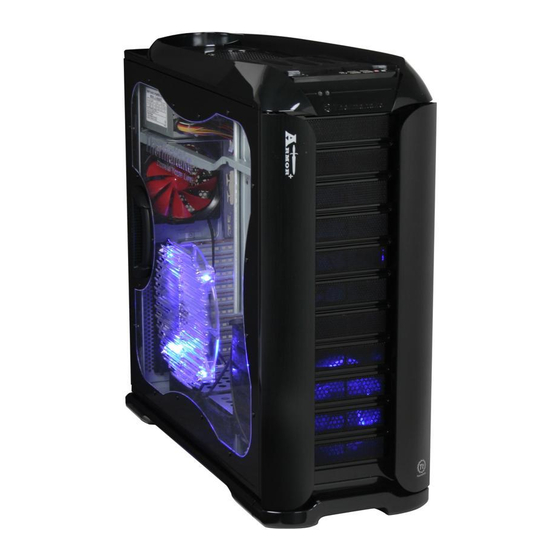
- Page 1 Beyond the pass, Exceed the present, Surpass the competition. 2007 Thermaltake Technology Co., Ltd. All Rights Reserved. 2007.10 All other registered trademarks belong to their respective companies. www.thermaltake.com Tested To Comply With FCC Standards FOR HOME OR OFFICE USE VH6000 Series...
-
Page 2: Chapter 1. Product Introduction
Chapter 1. Product Introduction Contents Specification Chapter 1. Product Introduction Specification Chapter 2. Case Mechanical Operation How to Open the Side Panel -Open the transparent side panel -Open the right-hand side panel 5.25" Device Installation -How to remove 5.25" device? -How to put back the 5.25"... -
Page 3: Chapter 2 Case Mechanical Operation
Chapter 2 Case Mechanical Operation 2.1 How to Open the Side Panel Open the transparent side panel Open the right-hand side panel To remove the transparent side panel, please remove upper and bottom thumb To remove the right-hand side panel, screws on the back of the case. -
Page 4: Device Installation
2.2 5.25" Device Installation How to remove 5.25" device? Pull the right-hand side of the lever to remove the 5.25" device. Remove the 5.25" drive bay cover as shown. How to put back the 5.25" drive bay cover? Put 5.25" device into the drive bay till the locked- position. -
Page 5: Hdd Installation
2.3 3.5" Device Installation 2.4 HDD Installation Place 3.5" device on the tray and fasten it using the screws provided. Remove the HDD tray by pressing the handle and pull the tray out. Slide the drive device into the bay and secure the tray by 5.25"... - Page 6 2.5 How to Remove the HDD Cage Slide the HDD tray back to the drive bay. Unscrew the thumb screws of the cage. Press the handle to lock the HDD tray. Push the handle down and pull the cage out. Organized HDD cable management.
-
Page 7: Power Supply Installation
2.6 PCI Slot Tool-Free Usage 2.7 Power Supply Installation Release the plastic clip as shown. Take off both side panels and unscrew the thumb screws from Take off the PCI bracket. both side of PSU supporting bridge. Locate Graphic Card to the motherboard through fixing it on the space of PCI bracket and insert it to the PCI slot. - Page 8 2.8 Sliding Motherboard Tray Adjust PSU supporting bridge to the appropriate position. Remove the screws from the back of the chassis. Fasten both side of PSU supporting bridge using the thumb screws. Slide the motherboard tray towards the back of the case to remove it from the case.
-
Page 9: Accessory Storage
2.9 Accessory Storage 2.10 Swappable HDD Module/ Fan Module (Optional) Top accessory storage The top sliding hood allows easy access to the extra storage space for small tools and accessories. Lay down your case and unscrew the thumbscrews to remove the HDD cage Storage draw (optional) Please find the storage draw from... -
Page 10: Motherboard Installation
Chapter3 Motherboard & Leads Installation 2.11 VGA Fan Installation (Optional) 3.1 Motherboard Installation Each motherboard has different standoff layout. It is highly suggested that you refer to your motherboard's manual when installing motherboard into the Case. Armor is applicable with Extend ATX, ATX & Micro ATX motherboards. Your motherboard may require a special I/O Panel, which should be included with your motherboard. -
Page 11: Usb Connection
3.2 Case LED connection 3.3 USB 2.0 & IEEE 1394 Firewire Connection USB connection Please consult your motherboard manual to find On the front of the case, you can find some LEDs and switch leads out the section of "USB connection". (POWER SW*1, POWER LED*1, H.D.D. -
Page 12: Ieee1394 Firewire Connection
3.4 Audio Connection Please refer to the following illustration of Audio connector and your motherboard IEEE1394 Firewire connection user manual. Please consult your motherboard manual to find Please select the motherboard which used AC'97 or HD Audio (Azalia), (be aware of out the section of "IEEE1394 Firewire connection". - Page 13 Furthermore, it has been approved by UL, CUL, TUV, CB, FCC, CE, and BSMI. There are three main products line of Thermaltake PSU which divided into Toughpower , Purepower (include Purepower RX) and TR2 (include TR2 RX) series.
- Page 14 VH6000 Series 25/26...
Need help?
Do you have a question about the Armor VH6000 Series and is the answer not in the manual?
Questions and answers