Table of Contents
Advertisement
Available languages
Available languages
Quick Links
Advertisement
Table of Contents

Related Manuals for Bticino 391504


Summary of Contents for Bticino 391504
- Page 1 MANUALE DI ISTRUZIONI 391504 Instructions manual USER MANUAL...
- Page 3 Prima di procedere all’installazione, leggere attentamente le istruzioni associate e individuare un luogo di montaggio idoneo in funzione del prodotto. Non aprire, smontare, alterare o modificare l’apparecchio eccetto speciale menzione indicata nel manuale. Tutti i prodotti Bticino devono essere esclusivamente aperti e riparati da personale adeguatamente formato e autorizzato da Bticino.
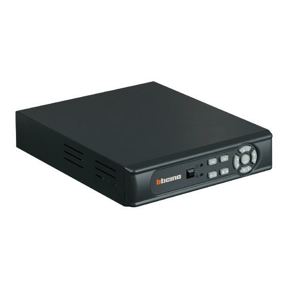
- Page 4 391504 DISTINTA DI SPEDIZIONE Assicurarsi che tutti i prodotti di seguito indicati siano presenti nella confezione. Se qualcosa manca, contattate il vostro rivenditore non appena possibile. Descrizione del prodotto Illustrazione del Prodotto QTÀ DC 12V/ 2.5A Adattatore di alimentazione ingresso: AC 100~240V Uscita: DC 12V/ 2.5A...
-
Page 5: Pannello Anteriore
NOME e FUNZIONE di CIASCUN COMPONENTE Pannello anteriore : LED indicatore di registrazione : Pulsante indietro : Pulsante avanti veloce/Invio selezione : Pulsante direzione sinistra/display schermo canale 2 : Pulsante direzione alto/display schermo canale 1 : Pulsante direzione destra/display schermo canale 4 : Invio/Uscita Menu : Pulsante direzione basso/display schermo canale 3 : Pulsante Registra/Stop... -
Page 6: Pannello Posteriore
391504 PANNELLO POSTERIORE (1) DC 12V [Terminale ingresso alimentazione]: presa di corrente. (2) Ingresso Video [VIDEO IN]: Collegamento alle videocamere. (3) Uscita Video [VIDEO OUT]: Collegamento al monitor. (4) Ingresso Audio [AUDIO IN]: Porta ingresso RCA per segnale audio (5) Uscita Audio [AUDIO OUTPUT]: Porta uscita RCA per segnale audio (6) USB: Collegamento a un dispositivo di archiviazione USB esterno (Plug and Play). -
Page 7: Installazione
INSTALLAZIONE Configurazione del sistema Impostare la connessione come indicato nell’immagine seguente: collegare la videocamera, il monitor e l’alimentazio- ne per avviare la modalità monitoraggio. Per effettuare un backup delle immagini, collegare il dispositivo di archivia- zione USB. Il DVR supporta anche un’uscita video VGA. Collegare al dispositivo di archiviazione USB Remarque :... - Page 8 391504 391504 TELECOMANDO 8. TELECOMANDO (Facoltativo) Funzioni tasti telecomando ID telecomando Nome pulsante Descrizione 1 CHECK ID ID Telecomando Indietro Pulsante avanti veloce/inserire scelta. MENU Invio/Uscita Menu Pulsante direzione alto / display schermo canale 1 Pulsante direzione basso / display schermo canale 3...
-
Page 9: Procedura Operativa
PROCEDURA OPERATIVA Accensione Dopo l’accensione, il DVR rileverà automaticamente le periferiche (auto-test, auto rilevazione dell’hard disk, ecc.) Il sistema rileverà l’ingresso video e valuterà se il sistema video è PAL. Qualora non fosse possibile rilevare l’ingresso video (PERDITA VIDEO), il sistema invierà un allarme (non influenzando la registrazione in corso, ma quando tutte le immagini video (canale 1 –... -
Page 10: Modalità Registrazione
391504 MODALITÀ REGISTRAZIONE Descrizione Icone Canale 2 : Lo schermo nero indica che il display e la funzione di registrazione sono SPENTI. Canale 3 : Lo schermo blu indica una perdita video. [M] : Il simbolo [M] indica registrazione manuale. -
Page 11: Modalità Riproduzione
MODALITÀ RIPRODUZIONE 1. Premere il pulsante Play ( ) per entrare nel display “Cerca data/ora”. 2. Premere il pulsante Avanti veloce ( ) per entrare nella modalità “Configura orario”. Dopo aver impostato l’orario, premere il pulsante (MENU )p er tornare alla schermata Ricerca Orario e premere il pulsante Play ( ) di nuovo per visualizzare l’orario selezionato. -
Page 13: Specification
Before carrying out the installation, read the instructions and take account of the product’s specific mounting location. Do not open up, dismantle, alter or modify the device except where specifically required to do so by the instructions. All Bticino products must be opened and repaired exclusively by personnel trained and approved by Bticino. -
Page 14: Packing List
391504 PACKING LIST PACKING LIST Check to make sure all of the items shown below are included in your product package. If something is missing, contact Check to make sure all of the items shown below are included in your product package. If something is missing, contact your your dealer as soon as possible. -
Page 15: Name And Function Of Each Part
NAME and FUNCTION of EACH PART Front panel : LED indicatore di registrazione LED indicatore di registrazione. : Pulsante indietro Pulsante indietro : Pulsante avanti veloce/Invio selezione Pulsante avanti veloce/Invio selezione. : Pulsante direzione sinistra/display schermo canale 2 (4) : Pulsante direzione sinistra/display schermo canale 2 Pulsante direzione alto/display schermo canale 1 : Pulsante direzione alto/display schermo canale 1... -
Page 16: Rear Panel
391504 REAR PANEL (1) DC 12V [Power Input terminal]: power socket. (2) Video Input [VIDEO IN]: Connect to cameras. (3) Video Output [VIDEO OUT]: Connect to the monitor. (4) Audio Input [AUDIO IN] : RCA input port for an audio signal (5) Audio Output [AUDIO OUTPUT] : RCA output port for an audio signal (6) USB: Connect to external USB storage device (Plug and Play). -
Page 17: Installation
INSTALLATION System configuration Please setup the connection by following the illustration shown below: Connect camera, monitor and power to enter monitoring mode. To backup images, connect the USB storage device. The DVR also supports VGA video output. -
Page 18: Remote Control
391504 REMOTE CONTROL Remote Control ID Enter MENU and select item Remote Control ID to setup remote controller ID. (1) Enter MENU find item Remote Control ID and setup a set of number for CHECK ID (Remote control ID consists of 10 sets of the numbers: ALL, 11, 12, 13, 21, 22, 23, 31, 32, 33). -
Page 19: Operating Procedure
OPERATING PROCEDURE Power on After power on, DVR will auto-detect its peripherals (self-testing, auto detects the hard disk, and etc.). The system will detect the video input and judge whether the video system is PAL. When video input is unable to be detected (VIDEO LOSS), the system will send out an alarm (it will not affect the actual recording, but when all (1CH-4CH) video images disappears, the DVR will stop recording). -
Page 20: Record Mode
391504 RECORD MODE Icon Description : Black screen indicates display and record function switched OFF. : Blue screen indicates video-loss. : Symbol [M] indicates manual recording. Symbol [S] indicates schedule recording. When both manual and schedule recording has been enabled, : Currently under recording. -
Page 21: Playback Mode
PLAYBACK MODE 1. Press Play ( ) button to enter “Time Search” display. 2. Press Fast Forward ( ) button to enter Time Setup mode. After time setup has been completed, press (MENU ) button to return to Time Search display and press Play ( ) button again to playback the selected time.
Need help?
Do you have a question about the 391504 and is the answer not in the manual?
Questions and answers