Table of Contents
Advertisement
ASR Audio Systems Friedrich Schaefer, D-35745 Herborn, Germany +49 / 2772 - 42 905
0.0 Table of Contents of this manual
1.0 Receiving the ASR Emitter - First moves.......................................................2
1.1 Unpacking the ASR Emitter........................................................................................2
1.2 Important safety precautions.......................................................................................2
1.3 Placing the Emitter units..............................................................................................3
2.0 Connecting the ASR Emitter to your system..................................................3
2.1 Standard connections .................................................................................................4
2.2 The balanced input.......................................................................................................4
2.3 Connecting a turntable to the ASR Emitter ..............................................................4
2.4 Connecting a high-level source to the direct input ...................................................5
2.5 Connecting a tape deck to the ASR Emitter.................................................................5
2.6 Connecting speakers to the ASR Emitter.....................................................................5
2.7 Connecting the separate power supplies to the ASR Emitter.......................................6
2.8 Connecting the ASR Battery Power Supply.................................................................7
2.9 Burn-in time..................................................................................................................7
3.0 Operating the ASR Emitter..............................................................................8
3.1 General operation of the ASR Emitter.........................................................................8
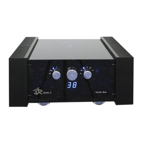
3.2 Front panel control knobs of the ASR Emitter.............................................................8
3.3 Operating the ASR Emitter via ASR remote control..................................................10
3.4 Adjustments of the ASR Emitter................................................................................10
4.0 Protection circuits of the ASR Emitter..........................................................12
4.1 Impedance-check before the ASR Emitter is switched ON.......................................12
4.2 Distortion- and Overload-protection circuit...............................................................13
4.3 Over-temperature protection circuit...........................................................................13
5.0 Maintenance of the ASR Emitter...................................................................13
5.1 Cleaning of the ASR Emitter.....................................................................................13
5.2 Resetting the ASR Emitter after malfunctions...........................................................14
5.3 Description of Leds shining in operation...................................................................14
5.4 Checking fuses in the power supply units..................................................................14
5.5 External battery power supply....................................................................................14
5.6 The Emitter is not reacting on remote control signals................................................15
5.7 Noise from the main unit while warming up/cooling off...........................................15
5.8 Just in case: repair.......................................................................................................15
6.0 Function description of ASR Emitter............ ...............................................15
6.1 Function description of ASR Emitter main unit.........................................................15
6.2 Function description of the external power supply... ........ ........................................17
6.3 Function description of the ASR battery power supply..............................................18
7.0 Technical Data.................................................................................................19
High End Integrated Amplifier ASR Emitter I and II version 2009 on Page 1
Advertisement
Table of Contents

Related Manuals for ASR Emitter


Summary of Contents for ASR Emitter
-
Page 1: Table Of Contents
6.1 Function description of ASR Emitter main unit............15 6.2 Function description of the external power supply...........17 6.3 Function description of the ASR battery power supply..........18 7.0 Technical Data....................19 High End Integrated Amplifier ASR Emitter I and II version 2009 on Page 1... -
Page 2: Receiving The Asr Emitter - First Moves
Receiving the ASR Emitter – First moves Unpacking the ASR Emitter Use care in unpacking your ASR Emitter. Please don’t cut the tapes of the wrapping and keep the packing for maybe necessary transports. Please inspect the units for any shipping damage and call your dealer immediately if any is found. -
Page 3: Placing The Emitter Units
Placing the Emitter units The heat sinks of the ASR Emitter radiate some heat, so please place the main unit in a place, where air can circulate around the heat sinks. Never put another unit on top of the main unit. -
Page 4: Standard Connections
= when you have only one signal source The additional RCA sockets (on the back panel, outer left/right side) are tape outputs – the ASR Emitter I is equipped with one, the ASR Emitter II with two tape out RCA sockets. These outputs are named „Out“. - Page 5 Better sound quality can be achieved with a separate Phone preamp like the ASR Basis. The output of the phono preamp should be connected to the Ph inputs at the Emitter. High End Integrated Amplifier ASR Emitter I and II version 2009 on Page 5...
-
Page 6: Connecting A High-Level Source To The Direct Input
Connect the „Line out“ or „Tape Out“-RCA sockets on your tape deck to the RCA input sockets „DT“ on the ASR Emitter and the „Line In“- or „Tape In“-RCA sockets on your tape deck to the „Out“-RCA sockets (sockets closest to the heat sinks) on the ASR Emitter. -
Page 7: Connecting The Separate Power Supplies To The Asr Emitter
to listen to music again, the left control knob on the ASR Emitter has to be switched OFF for some seconds to restart the operation of the amplifier. -
Page 8: Connecting The Asr Battery Power Supply
ASR Battery Power Supply Burn-in time Straight out of the box, the performance of the ASR Emitter is not as impressive as the performance of a unit that has been used for longer time and so is broken in. Why? Each ASR Emitter needs at least 100 to 200 hours of playing music to break in. -
Page 9: Operating The Asr Emitter
ASR Emitter are cut in half in this mode. For a longer life of the built in parts, after switching ON the ASR Emitter is operating in the energy saving mode for one minute. - Page 10 Emitter is turned ON, pressing the tape monitor switch allows you to listen to the rear band signal. When the monitor input is activate a green bar in the display is shining. When the ASR Emitter is in the „Standby“-mode, pressing the tape-monitor switch activates the adjustments mode.(See 3.4)
-
Page 11: Operating The Asr Emitter Via Asr Remote Control
To adjust the parameter, please press either the “Vol”-buttons on the ASR remote control or turn the middle knob on the ASR Emitter to the right (+) or left (-). To save your individual adjustments please put the left knob of the ASR Emitter to the „OFF“-position and keep the unit switched OFF for at least ten seconds. - Page 12 Please press the “Mode”-button on the ASR remote control (or the „Tape Monitor“-button on the front plate) three times – the two yellow display numbers are flashing. Now either use the “Vol“- buttons on the ASR remote control or the middle knob of the ASR Emitter to adjust the display. left display number...
-
Page 13: Protection Circuits Of The Asr Emitter
“Vol”-button = decreases input level) on the ASR remote control or the middle knob of the ASR Emitter to adjust the input level for the chosen input. For all other inputs do equal. Adjusting the configuration of the ASR Emitter The ASR Emitter is equipped with internal DIP switches to configure the unit. -
Page 14: Distortion- And Overload-Protection Circuit
The ASR Emitter is equipped with a sensitive over-temperature protection circuit. Temperature sensors are located at the large heat sinks of the ASR Emitter. If these sensors detect a temperature > 55° Celsius, the ASR Emitter will be switched off. The display indicates the switch off with a flashing Led (red) „Overheat“. -
Page 15: Resetting The Asr Emitter After Malfunctions
„Standby“-position now you can switch the ASR Emitter ON again by either putting the left knob to the „1“- postion or by pressing the „On/Off“-button on the remote control Description of Leds shining in operation... -
Page 16: The Emitter Is Not Reacting On Remote Control Signals
The Emitter is not reacting on remote control signals At first please check if the Emitter is switched OFF- in this case the remote will not work. Then check if the led on the remote controller is flashing green when you push a button. - Page 17 In “Full power mode” this 8 Leds will shine brighter with the full voltage. The lock from above onto the main PCB board of Emitter II ( Em I next page ) : High End Integrated Amplifier ASR Emitter I and II version 2009 on Page 17...
- Page 18 After switching ON in Energy mode the yellow led Energy ON in the middle shows that the Emitter main unit has switched ON the PSU, then the two relays in the middle RE3, RE4 are switching and then the 2 yellow and two green Driver Leds are shining.
- Page 19 Also during charging the batteries the Emitter is working and you can still listen to music. when the batteries are fully charged at 19,5 Volts, the charging transformer will be turned Off, and the ASR Emitter Exclusive is supplied out of the batteries.
-
Page 20: Technical Data
External power supply with 2x 700 VA (ASR Emitter I )/ power supplies with 4x 700 VA (ASR Emitter II) rated power, with more than 1000 VA output (impulse) for each Philbert- Mantelschnitt- transformer, separate transformers and rectifiers for positive and negative voltages (two transformers each in separated cases per channel for the ASR Emitter II). - Page 21 Internet : http://www.ASRAudio.com Note: ASR Audio Systems reserves the right to change specifications without notice as design improvements are incorporated. Copyright January 2011 Friedrich Schaefer, ASR Audio High End Integrated Amplifier ASR Emitter I and II version 2009 on Page 21...
Need help?
Do you have a question about the Emitter and is the answer not in the manual?
Questions and answers