Table of Contents
Advertisement
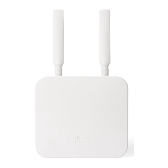
MG21/MG21E Installation Guide
About This Guide
This guide provides instruction on how to install and configure your MG series cellular gateway. This guide also provides
mounting instructions and limited troubleshooting procedures.
Physical Specifications
Models
Dimensions (w x d x h)
Weight (without
accessories)
Power Supply
Power Load
Operating Temperature
Humidity
Product View and Physical Features
Front Panel
MG21
160.45 x 160.45 x 34.45mm
497g
12V/2.5A 48-57V/0.35A
10 Watt Maximum
(PoE 802.3AF)
4°F to 122°F (-20°C to 50°C)
5% to 95% non-condensing
MG21E
165.7 x 160.45 x 34.45mm
489g
12V/2.5A 48-57V/0.35A
10 Watt Maximum (PoE 802.3AF)
4°F to 122°F (-20°C to 50°C)
5% to 95% non-condensing
1
Advertisement
Table of Contents

Summary of Contents for Cisco MERAKI MG21
-
Page 1: About This Guide
MG21/MG21E Installation Guide About This Guide This guide provides instruction on how to install and configure your MG series cellular gateway. This guide also provides mounting instructions and limited troubleshooting procedures. Physical Specifications Models MG21 MG21E Dimensions (w x d x h) 160.45 x 160.45 x 34.45mm... -
Page 2: Back Panel
Back Panel... -
Page 3: Side Panels
Side Panels... -
Page 5: Status Indicator
Status Indicator The MG series of devices use an LED to inform the user of the device's status. LED patterns and their meanings are described below. LED Status Meaning Solid orange Power is applied but the appliance is not connected to the Meraki Dashboard Alternating Colors The appliance is attempting to connect to Meraki Dashboard... -
Page 6: Ethernet Port
Solid White Fully operational/connected Ethernet Port The MG21/MG21E features two Ethernet ports. Port 1 can be reconfigured to Safe Mode for troubleshooting diagnostics. Brand new units will ship with both ports configured as LAN, which is the default, normal operating mode. -
Page 7: Package Contents
MG smart dipole antennas and smart patch antenna. Usage of non-Meraki accessories may damage the MG and degrade performance. The Cisco Meraki antennas are designed for the maximum allowable gain without exceeding the EIRP for local regulatory domains on their supported bands. -
Page 8: Pre-Install Preparation
You should complete the following steps before going on-site to perform an installation. Configure the Dashboard Network The following is a brief overview only of the steps required to add an MG21 to your network. For detailed instructions about creating, configuring and managing Meraki networks, refer to our online documentation portal. - Page 9 4. If the unit requires a firmware upgrade after coming online, the power LED will begin blinking white until the upgrade is complete, at which point the LED will turn solid white. You should allow at least a few minutes for the firmware upgrade to complete, depending on the speed of your internet connection.
-
Page 10: Installation Instructions
1. Disconnect power to the MG21. WARNING: The MG21 and MG21E are IP67 rated only when the back panel plate is attached and screwed down with the gasket in place. Hot swapping/installing SIM cards while the MG21 is powered on may cause unexpected behavior or errors and is not recommended. - Page 11 3. Push the tray up and it will click. This unlocks the tray so you can flip up the cage. Insert your activated nano (4FF) SIM card into the SIM card tray. 4. Make sure your SIM card is aligned properly with the notch.
- Page 12 5. Before closing the SIM cage, make sure the the cage is aligned properly. The left picture below shows a cage misalignment. Pressing down with the wrong alignment could damage the cover. The right picture below shows proper cage alignment.
- Page 13 6. Close the SIM cage with proper alignment and lightly press down on the cover. Move the cage down and there should be a click to confirm the cage is locking in the SIM card to the tray. 7. Once the SIM card is locked in, it should stay within the tray.
-
Page 14: Connecting To Wan
(ex: wi-fi) on your client machine. Follow the steps below to configure basic connectivity and other cellular gateway parameters on the MG21: 1. Using a client machine such as a laptop, connect cirectly to LAN interface of the MG. -
Page 15: Configuring Ethernet Ports
If you are still experiencing hardware issues, please contact Cisco Meraki Support by logging in to dashboard and using the Help > Get Help option at the top of the page, then opening an email case or calling the Meraki Support center... -
Page 16: Warranty
Note: Meraki MG21 and MG21E devices have been tested and found to comply with the limits for a Class B digital device, pursuant to part 15 of the FCC rules. These limits are designed to provide reasonable protection against harmful interference in a residential installation.
Need help?
Do you have a question about the MG21 and is the answer not in the manual?
Questions and answers