Table of Contents
Advertisement
Advertisement
Table of Contents

Summary of Contents for GoldCruise GC90Ci
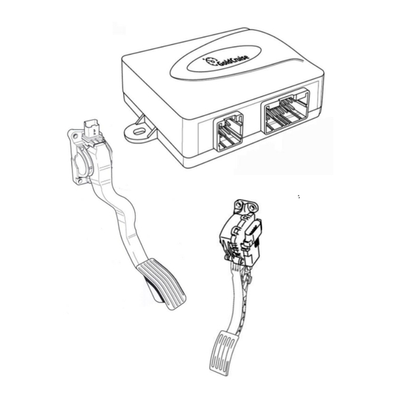
- Page 1 CAN-bus Cruisecontrol GC90Ci Installation manual From Software version 1.8.5...
- Page 2 This installation manual was written for installers with knowledge of modern vehicle technology and experience in working on these vehicles. The GC90Ci GoldCruise is a modular product of John Gold International BV, that has been designed and produced with great care and precision.
-
Page 3: Table Of Contents
CAN-bus Cruisecontrol GC90Ci installation manual Contents Contents ..........................2 Purpose, construction and operation of the GC90Ci ........... 3 Purpose of the GC90Ci .................... 3 Construction ......................3 Operation ........................ 3 Safety directions ......................4 Installation and connections ..................6 Installation electronic module (EM) ............... 6 Wiring Diagram ....................... -
Page 4: Purpose, Construction And Operation Of The Gc90Ci
This means that the signal structure in the ECU is not altered at all. Because the accelerator pedal is learnt to the system, the GC90Ci GoldCruise or speed limiter can make optimal use of the available engine power. -
Page 5: Safety Directions
2 Safety directions To ensure safety the GC90Ci complies with the following labels. For the GC90Ci the following safety instructions apply, also printed in the item it concerns: Only use the GC90Ci for the purpose as described in this installation manual... - Page 6 CAN-wires are twisted to assure a reliable operation. Make sure that the twisting remains the same when the CAN-wires are shortened or extended As the GC90Ci is supplied model specific, it is not necessary to learn the accelerator pedal and speed signal. The GC90Ci will operate directly after...
-
Page 7: Installation And Connections
CAN-bus Cruisecontrol GC90Ci installation manual Installation and connections 3.1 Installation electronic module (EM) Always install the EM in a position where heat, vibration and moisture are minimized, such as underneath the dashboard, never in the engine compartment. The installation kit contains tie-wraps, double-sided tape and screws that can be used to install the EM. -
Page 8: Wiring Diagram
CAN-bus Cruisecontrol GC90Ci installation manual 3.2 Wiring Diagram OBD connector... -
Page 9: T-Harness Connection
CAN-wires are twisted to assure a reliable operation. Make sure that the twisting remains the same when the CAN-wires are shortened or extended As the GC90Ci is supplied model specific. Connect the wiring harness as instructed in the supplied specific installation manual. - Page 10 Before using the ML90Ci Multi limiter should be released. Hereby the ML90Ci checks or the CAN-bus signal for the brake is stable As the GC90Ci is supplied model specific, it is not necessary to learn the accelerator pedal and speed signal. The GC90Ci will operate directly after...
-
Page 11: Set-Up
CANCEL The GC90Ci is supplied make/modelspecific with carefully selected settings. Yet there is the possibility that the chosen settings are different than the required settings. In that case it is possible to learn the accelerator pedal and speed signal manually: refer to §... -
Page 12: Release Procedure
CAN-bus Cruisecontrol GC90Ci installation manual 4.2 Release procedure The GC90Ci is secured with an release procedure, this procedure checks if there is a proper CAN-bus brake signal available and properly programmed. The Cruisecontrol askes you with beep-signals to press and release the brake pedal. This procedure needs to be performed once after installation. -
Page 13: The Cg90Ci Accelerator Pedal Set-Up
CAN-bus Cruisecontrol GC90Ci installation manual 4.3 The CG90Ci accelerator pedal set-up This step is only necessary in case the programmed settings of the GC90Ci do not match the required settings. Perform the following steps to learn the GC90Ci to the accelerator pedal. -
Page 14: The Cg90Ci Vehicle Speed Signal Set-Up
CAN-bus Cruisecontrol GC90Ci installation manual 4.4 The CG90Ci vehicle speed signal set-up This step is only necessary in case the programmed settings of the GC90Ci do not match the required settings. Perform the following to learn the GC90Ci to the vehicle speed signal. -
Page 15: Testdrive
CAN-bus Cruisecontrol GC90Ci installation manual 4.5 Testdrive Step Action Confirmation Switch the ignition OFF and ON Start the engine 2 low beeps Switch the Cruisecontrol ON Drive 90 km/h (55 mph) on the highway and Cruise control engage and operate... -
Page 16: Increase Response Time
CAN-bus Cruisecontrol GC90Ci installation manual 4.6 Increase response time Perform the following steps to increase the response time. Perform step 1-7 within 1 minute! Step Action Confirmation Switch the ignition OFF and ON Start the engine 2 low beeps Switch the Cruisecontrol ON... -
Page 17: Reduce Response Time
CAN-bus Cruisecontrol GC90Ci installation manual 4.7 Reduce response time Perform the following steps to reduce the response time. Perform step 1-7 within 1 minute! Step Action Confirmation Switch the ignition OFF and ON Start the engine 2 low beeps Switch the Cruisecontrol ON... -
Page 18: Increase Sensitivity
CAN-bus Cruisecontrol GC90Ci installation manual 4.8 Increase sensitivity Perform the following steps to increase the sensitivity. Perform step 1-7 within 1 minute! Step Action Confirmation Switch the ignition OFF and ON Start the engine 2 beeps low Switch the Cruisecontrol ON... -
Page 19: Reduce Sensitivity
CAN-bus Cruisecontrol GC90Ci installation manual 4.9 Reduce sensitivity Perform the following steps to increase the sensitivity. Perform step 1-7 within 1 minute! Step Action Confirmation Switch the ignition OFF and ON Start the engine 2 beeps low Switch the Cruisecontrol ON... -
Page 20: Diagnostics And Trouble Shoot
CAN-bus Cruisecontrol GC90Ci installation manual 5 Diagnostics and trouble shoot 5.1 Diagnostics 1: CM, brake signal, clutch signal Step Action Confirmation Switch the ignition completely OFF Operate and hold Switch the ignition ON and wait for beeps Beeps pulsating Release... -
Page 21: Diagnostics 2:Accelerator Pedal Control, Vehicle Speed Signal
CAN-bus Cruisecontrol GC90Ci installation manual 5.2 Diagnostics 2:Accelerator pedal control, vehicle speed signal Step Action Confirmation Lock the handbrake and put the gear in neutral Switch the ignition completely OFF Operate and hold Start the engine and wait for beeps... -
Page 22: Trouble Shoot 1
CAN-bus Cruisecontrol GC90Ci installation manual 5.3 Trouble shoot 1 Step Action Confirmation low beep and Operate EM-LED turns red (Does not operate: Refer to § 5.4 Trouble shoot 2) low beep and Operate EM-LED turns red (Does not operate: Refer to § 5.4 Trouble shoot 2) Check that the power supply +12V is connected correctly. -
Page 23: Frequently Asked Questions
(yet). Perform the accelerator pedal set- accelerator pedal set-up up. Refer to § 4.3 Accelerator pedal set-up 1. The GC90Ci is not properly learned to the accelerator pedal. Re-perform the accelerator pedal set-up. Refer to § 4.3 Accelerator pedal The cruisecontrol picks up set-up. - Page 24 CAN-bus Cruisecontrol GC90Ci installation manual John Gold International BV © 2013 John Gold International BV S. E. & O PO Box 1603,1300 BP Almere Copying or distributing (contents of this the Netherlands installation manual is only permitted with www.johngold.com written authorisation by John Gold...
Need help?
Do you have a question about the GC90Ci and is the answer not in the manual?
Questions and answers