Advertisement
Quick Links
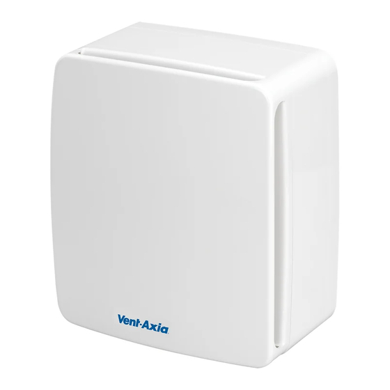
Centrif Duo &
Centrif Duo Plus
Installation and Wiring Instructions
220-240V~50Hz
PLEASE READ INSTRUCTIONS IN CONJUNCTION WITH ILLUSTRATIONS. PLEASE SAVE THESE
INSTRUCTIONS.
Centrif Duo Plus
Stock Ref. N°
Centrif Duo P 25 61 20D
Centrif Duo T 25 62 20D
Centrif Duo DP 25 63 20D
Centrif Duo HTP 25 64 20D
Centrif Duo Plus P 43 16 13B
Centrif Duo Plus T 43 16 14B
Centrif Duo Plus DP 43 16 15B
Centrif Duo Plus HTP 43 16 16B
Centrif Duo
IPX4
Advertisement

Related Manuals for Vent-Axia Centrif Duo Series


Summary of Contents for Vent-Axia Centrif Duo Series
- Page 1 Centrif Duo & Centrif Duo Plus Installation and Wiring Instructions Stock Ref. N° Centrif Duo P 25 61 20D Centrif Duo T 25 62 20D Centrif Duo DP 25 63 20D Centrif Duo HTP 25 64 20D Centrif Duo Plus P 43 16 13B Centrif Duo Plus T 43 16 14B Centrif Duo Plus DP 43 16 15B Centrif Duo Plus HTP 43 16 16B...
- Page 2 Centrif Duo and Centrif Duo Plus Features Surface mountable ● ● ● ● Flush mountable with accessory kit (available ● ● ● ● separately) Washable filter (available separately for ● ● ● ● Centrif Duo Plus) Pullcord ● ● ● Trickle speed ●...
-
Page 3: Safety And Guidance Notes
C. Ensure that the mains supply (voltage, frequency, and phase) complies with the rating label. D. The fan should only be used in conjunction with the appropriate Vent-Axia products. E. It is recommended that the connection to the fan connector terminals is made with flexible cable. - Page 4 SURFACE MOUNTING (PANEL/CEILING) Remove the Front Cover Assembly by slackening the two screws by two turns (fig.2.) Lift the front assembly away from the bottom edge first, then the top edge. Cut a 105mm hole, then suitable screw holes in the panel, ensuring that there is sufficient space for the product to be installed and that the filter (sold separately for the Centrif Duo Plus) can be removed for maintenance.
- Page 5 removed for maintenance. IMPORTANT: Be careful to avoid joists and hidden pipes or cables. Remove the Back Box pieces by removing the four screws (fig 5). Replace it with the Frame from the Flush Mount Kit. Pass each of the long Panel Clip Screws (fig.6) supplied in the kit fully through the flange of the Chassis and screw in to the four Panel Clips allowing enough space between the clip and the flange for the thickness of the panel (so that the clips can spring open behind the panel).
- Page 6 iii) T model: Move one of the following dip switches into the ON position. Dip switch 1 = Low speed (same as trickle speed) Dip switch 2 = Medium (Utility) speed Dip switch 3 = High (Kitchen) speed HTP model: The HTP model has two boost speed options, one speed option for the Timer function (via LS) or pullcord and another speed selection for the Humidistat function.
-
Page 7: Servicing And Maintenance
D. SERVICING AND MAINTENANCE. WARNING: THE FAN AND ANCILLARY CONTROL EQUIPMENT MUST BE ISOLATED FROM THE POWER SUPPLY DURING SERVICING AND MAINTENANCE. At intervals appropriate to the installation, the fan should be inspected and cleaned to ensure there is no build up of dirt or other deposits. If fitted, remove the Filter (fig.2 &... - Page 8 Centrif Duo Plus shown Fig.3. Terminal Block Cover. Spigot. Cover Assembly. Chassis Assembly. Impeller. Centrif Duo Plus Optional Filter. (The Centrif Duo models have a metal mesh filter clipped on to the rear of the cover. It can be removed easily and washed too.) Fig.4.
- Page 9 Fig.5. Frame from optional Flush Mount Kit. 4 screws Back Box. Fig.6. Panel Clip Screw (4 off). Panel Clip (4 off). Chassis.
- Page 10 Fig 7. Setup WARNING: THE FAN AND ANCILLARY CONTROL EQUIPMENT MUST BE ISOLATED FROM THE POWER SUPPLY DURING INSTALLATION OR MAINTENANCE. TO ACCESS THE SPEED CONTROLS/PCB, REMOVE THE TWO SCREWS HOLDING THE PCB COVER IN PLACE (SEE FIG 4).
- Page 11 Fig 8. Siting of the fan. Fig 9. Wiring diagram without LS connection. 1 Phase Supply (220-240V 50 Hz) 3A Fuse 2 Pole Isolator Switch Pull Cord (if applicable) Fig 10. Wiring diagram with LS connection. 1 Phase Supply (220-240V 50 Hz) Ceiling Junction Fuse...
-
Page 12: Product Fiche
PRODUCT FICHE For Residential Ventilation Units (Complying Commission Delegated Regulation (EU) No 1254/2014) Name: Vent‐Axia Vent‐Axia Vent‐Axia Vent‐Axia Centrif Duo P ‐ Centrif Duo T ‐ Centrif Duo DP Centrif Duo HTP ‐ Model ID (Stock Ref.) : 256120 256220 ‐ 256320 256420 SEC Class D D D D SEC Value ('Average') 26.23 26.23 26.23 26.23 SEC Value ('Warm') 11.86 11.86 11.86 ... - Page 13 Name: Vent‐Axia Vent‐Axia Vent‐Axia Vent‐Axia Centrif Duo Centrif Duo Centrif Duo Centrif Duo Model ID (Stock Ref.) : Plus DP ‐ Plus HTP ‐ Plus P ‐ 431613 Plus T ‐ 431614 431615 431616 SEC Class D D D D SEC Value ('Average') 26.23 26.23 26.23 26.23 SEC Value ('Warm') 11.86 11.86 11.86 11.86 SEC Value ('Cold') 51.31 51.31 51.31 51.31 Label Required? (Yes/No=Out of scope) Yes Yes Yes Yes ...
- Page 14 Notes:-...
- Page 15 Notes:-...
- Page 16 Vent-Axia guarantees its products for two years from date of purchase against faulty material or workmanship. In the event of any part being found to be defective, the product will be repaired, or at the Company’s option replaced, without charge, provided that the product:- ...
Need help?
Do you have a question about the Centrif Duo Series and is the answer not in the manual?
Questions and answers