Table of Contents
Advertisement
Advertisement
Table of Contents

Related Manuals for Raven MPV 7100

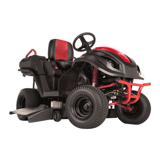
Summary of Contents for Raven MPV 7100
- Page 1 Raven 7100 Service Manual...
- Page 2 12v Battery Exchange...
- Page 3 12 Volt Battery Exchange Work Instructions Tools Needed for Installation: 8 mm T-Handle • 8 mm “T”-Handle Wrench 8 mm socket and Wrench Battery Impact Drill • 10 mm Socket and ratchet • 10 mm Open End Wrench • Volt Meter •...
- Page 4 12 Volt Relay Exchange...
- Page 5 12 Volt Relay Remove/Replace Installation Instructions Tools: • 8 mm Driver • 10 mm Driver Instruction Text 1. To remove the relays from frame use the Driver to remove the hotplate post (fig.A) 2. Use the 8 mm drive to remove the 8mm screw. (fig B) 3.
- Page 6 48 Volt Battery Pack Removal...
- Page 7 48 Volt Battery Removal Work Instructions Tools: Battery Tray Oil Plug Assembly • 8 mm T-Handle • 10mm Wrench • Jack • Battery Tray Parts: • Battery Tray Jack Removing the Battery 8mm Wrench IMPORTANT: Turn off power & remove key. Screw Oil Drain Plug 1.
- Page 8 Blade Motor Controllers...
- Page 9 Un-Connecting the Blade Motor Controller Installation Instructions Tools: • Phillips screwdriver • 10 mm driver • Utility knife Instruction Text 1. Remove the protective covers with Phillips screwdriver.(Fig A) 2. The yellow junction box covers should be removed. Please observe the junction box with the opt coupler.(Fig B) 3.
- Page 10 Blade Motor Controller (BMC) Install Installation Instructions Tools: • 10 mm Driver • Philips screw driver • 5mm Allen Driver Instruction Text 1. Attach BMC by re installing the 5mm button head screws and the 10mm nut.(Fig A) 2. Attach the three wires on the junction box. Blue Green and Yellow.
- Page 11 Carburetor Replacement...
- Page 12 Carburetor Replacement Removal/Installation Instructions Tools: Parts: • • Needle-nose pliers New Green Gasket • New Gray Gasket 1. Use needle-nose pliers to carefully remove the speed regulator spring from the speed regulator lever. It may be necessary to turn the lever by hand in order to remove the spring. Carefully remove the speed regulator pull rod from the speed regulator lever.
- Page 13 Carburetor Replacement Removal/Installation Instructions 3. Locate manifold spacer and slide of the mounting studs. It will be necessary to lift the spark plug wire to remove it. Remove and discard the gray carburetor gasket. Ensure that no remnants of old gasket remain. 4.
- Page 14 Carburetor Replacement Removal/Installation Instructions 6. Reattach both the speed regulator pull rod and spring to the speed regulator lever. It may be necessary to turn the lever by hand in order to install both rod and spring. Denver Global Products 1000 East Powell Dr. | Lincolnton, NC 28092 U.S.A ©...
- Page 15 Gasket Callout-Carburetor Instructions Tools: Parts: • none • gaskets - 5 Gasket Callout IMPORTANT: Turn off power & remove key. 1. Identify the gasket used between the engine block and the manifold spacer (see Figure A). The gasket must Engine Block and be in the same position as Figure A before attaching.
- Page 16 Contactor Fuse Replacement...
- Page 17 Contactor Cover and L-Shaped Bracket Instructions Tools: Parts: 3 Screws - Remove • Impact Drill • none Using Impact Drill • 8mm Wrench Contactor L-Shaped • 8mm Socket Cover Bracket Removing Contactor Cover and L- Shaped Bracket IMPORTANT: Turn off power & remove key. Top Screw on the Right 1.
- Page 18 Contactor Fuses Installation Instructions Tools: • Standard Socket Wrench - 3/8” Drive • 7mm Deep Well Socket - 3/8 Drive • 8mm Deep Well Socket - 3/8” Drive Double • 14mm Standard Socket - 3/8” Drive Fuse • 7/16” Wrench Holder 100A Fuse Parts:...
- Page 19 Contactor Fuses Installation Instructions 6. Locate (1) pair of the 12V wires (yellow/green & green). Singl e Fuse Hol der 12V Wiring on RH Contactor The yellow/green wire goes to the small LH post on the RH contactor and the solid green wires goes to the Yellow/Green Green small RH post (Fig.
- Page 20 Contactor Fuses Installation Instructions 16mm mounting screws (Fig. L). RH Contactor 13. On the RH contactor, use an 8mm socket and wrench to remove the (2) M5 x 12mm mounting screws attaching the contactor to the frame. Replace the LH screw with an M5 x 16mm mounting screw.
- Page 21 Drive Motor Controller Replacement...
- Page 22 Disassembly For DMC Change Assembly Instructions Tools: 5mm Allen bit (long) impact driver 10mm wrench 4mm Allen bit (long) Phillips head screwdriver 13mm wrench Parts: Hex socket screw M5 x 12 (90111-0TY0500-0001) Hex socket screw M6 x 16 (90111-0TY0200-0001) Seat console (82041-H200100-0001) Left side cover (82311-H200100-0001)
- Page 23 Remove Drive Motor Control Work Instructions 10mm T-Handle Tools: Bottom Bolt on Bracket • 10mm T-Handle • 8mm T-Handle Top Bolt on • Phillips Screwdriver Bracket 13mm Wrench • 10mm Wrench 10mm Wrench • Bracket 8mm Wrench • Remove Drive Motor Control 8mm or 10mm T-Handle POWER OFF AND REMOVE KEY.
- Page 24 Remove Drive Motor Control Work Instructions 8. Use the 13mm wrench to remove both caps - (1) red Red Terminal plastic cap and (1) black plastic cap (Fig. I). DMC Wiring Post w/White 9. Locate and remove the (2) 13mm nuts that are attached Sleeves to black and red terminal posts (Fig.
- Page 25 Drive Motor Control Installation Instructions Tools: • 10mm T-Handle Wrench • 10mm Deep Well Socket w/Ratchet (optional) Black & Red • 10mm Nut Driver (optional) Power Cables Board • 13mm Wrench Bracket Phillips Screwdriver • Impact Drill • Parts: • M8 x 20mm Flanged Hex Bolt (x4) - DMC •...
- Page 26 Drive Motor Control Installation Instructions 8. Locate red power cable and place onto the red power M8 Nut, Flat post, install M8 Flat Washer, Lock Washer and Hex Red Power Washer & Nut and tighten with 13mm wrench (Fig. H). Post Lock Washer 9.
- Page 27 Gas Gauge Check / Replacement...
- Page 28 Fuel Gauge Replacement Installation Instructions Tools: • Utility Knife • 10mm Driver Instruction Text 1. After removal of front plastics locate the fuel gauge assembly. (Fig A) 2. Use a 10mm driver to remove the fuel gauge fasteners. (Fig B) 3.
- Page 29 Fuel Gauge Inspection on the Finished MPV Work Instructions Connection wire of the subline Fuel Gauge Inspection on the Finished 1. Check and see if the wiring connection of the fuel gauge is complete and correct. Please refer to the following picture of wiring connection (see Figure A).
- Page 30 Oil Separator Replacement...
- Page 31 Oil Separator Filter Replacement Instructions Tools: Hose Strap • Needle-nose Pliers • Zip Tie Gun (set at minimum tension) Parts: • New Oil Separator Filter Old Oil Separator • 8” Zip Tie (x1) Hose Clamps Filter Replacing the Oil Separator Filter IMPORTANT: Turn off power &...
- Page 32 Oil Separator Filter Replacement Instructions IMPORTANT: When reconnecting the hoses to the new filter, it is recommended that the filter is inserted in New Oil Separator the hose end, the hose clamp is fully compressed and Filter slid towards the filter. Leave a slight amount of hose (approx.
- Page 33 PCB Replacement...
- Page 34 PCB Board Replacement Work Instructions Tools Needed for Installation: Pull Release Lever • 8 mm or 10 mm wrench • 5 mm Allen or T-Handle Wrench Remove Bolt • Phillips Screwdriver • 1/4” Nut Driver • Impact Drill Replacing the PCB Board Service Hatch 1.
- Page 35 PCB Board Replacement Work Instructions 11. Replace the top and bottom 8 or 10 mm bolts (Fig I & J). 12. QC INSPECTION: Steps 7 – 11 must be verified by Quality Control. 13. Re-attach the switch cover. 14. Replace the fender extension with the 5 mm Allen wrench.
- Page 36 MPV 7100 Specifications Series name MPV 7100 Engine displacement 420 cc Engine brand Raven Engine type single cylinder, 4 cycle Starter Electric starter standard Cutting range/Yard/(Acres) 2 to 10 acres Recommended for terrain type Cut width 46" Number of blades...
- Page 37 Front wheel size 18" Turf Tires Rear wheel size 20" Turf Tires Deck/anti scalp wheels number and size 4 points - 5" diameter Steering type Rack & pinion - deluxe wheel Adjustable steering wheel tilt adjustment Turning radius 14" Cruise control Maximum forward speed up to 17 MPH Maximum mowing speed...
- Page 38 STANDARD TORQUE VALUES Torque valve Item Specifications Foot Pounds Kg·m 5mm bolt, nut 0.55 6mm bolt, nut Standard 8mm bolt, nut 15.5 torque 10mm bolt, nut 3.75 12mm bolt, nut 40.5 Other Important System Torques: Transaxle Plug torque- 55 ft. Ibs Pillow block steering- 15 ft.
- Page 39 +12VDC +12VDC FWD/REV SEAT SWITCH PTO RELAY YG3 PTO ON WHITE / RED TO PTO DECK PLUG WHITE YH3 FWD VEHICLE R / W BLACK CONTROLLER HEADLIGHT PURPLE YELLOW YJ1 REV 04-4 SWITCH ORANGE BLACK PINK CRUISE BLUE / GREEN YH1 CRUISE +48VDC PURPLE...
- Page 40 AFT CONTACTOR FRONT CONTACTOR RECTIFIER OUTPUT PTO / DECK PLUG 04-8 100A GENERATOR SSR1 BROWN BLUE 120VAC 100A RECEPTACLES SSR2 100A MRBF FROM SEAT SWITCH 05-2 WHITE BATTERY, 48V WHITE PINK ORANGE BROWN BLACK YELLOW BLACK BLACK 48V CHARGE BLACK 4X 12V20AH WHITE GREEN...
- Page 41 FPM9-12B (12V9Ah) FirstPower Motorcycle Battery Dimensions Feature ◆ Motorcycle use. ◆ Absorbent glass mat technology. ◆ Maintenance-free. ◆ Highly efficient. ◆ Low shelf-discharge. ◆ Long cyclic life. Discharge Characteristics(25℃) Specifications 0.1C Nominal Voltage 12 V 0.2C 0.4C 10HR(10.8V) Capacity 0.6C (25℃) 1HR(9.60V) 5.8Ah...
- Page 42 FPM20-12 (12V20Ah) FirstPower Battery Dimensions Feature ◆ Absorbent glass mat technology. ◆ Maintenance-free. ◆ Highly efficient. ◆ Low shelf-discharge. ◆ Long cyclic life. Discharge Characteristics(25℃) 0.1C Specifications 0.2C 0.4C Nominal Voltage 12 V 0.6C Capacity 10HR(10.8V) 20Ah (25℃) 1HR(9.60V) 13Ah Length 177±2mm (6.97inch) Discharge Time (hour)
- Page 43 Symptom High Level Check System Check Remedy Unit does not function at all (dead silence) Neutral- 20 amp fuse open (No audible click) Generator switch off- Check 20amp fuse (yellow label fuse holder) and replace if needed Battery Voltage Low/ Check voltage- 12V starter battery low voltage, or battery Replace 12V battery or charge the battery.
- Page 44 Symptom High Level Check System Check Remedy Automatic choke has a manual override Engine runs erratically Air Filter is clogged ( Every 10 hours) this feature. If the curved wire lever above the air Push in manual override for choke should be cleaned.
- Page 45 Nothing happens with key in Engine Start 12 Volt battery may be low. Plug in charger. Generator panel switch is on position. Provided with Raven MPV. Not sitting properly on seat Seat switch 12V starter battery low voltage, or battery...
- Page 46 Symptom High Level Check System Check Remedy Will not drive forward Will not drive in reverse Will not drive forward or in reverse Generator switch is on. Unit not in neutral 100A battery fuse, 100A drive fuse, failed or Test and verify all too solve issue. missing 48V battery Will not drive forward Will not drive in reverse...
- Page 47 Symptom High Level Check System Check Remedy Uneven or erratic grass cut Mowing deck plugged Mowing across a slope - deck will move Mow up and down hills, rather than across laterally and cause a slight sawtooth cut. This slope is a built-in safety feature Poor cutting performance High lift blades are stamped 23-1125 Reg are...
- Page 48 Excessive noise and/or vibration when Damage to blades Damaged blade(s) Replace damaged blade(s) mowing Damaged/bent motor shaft Loose screws securing motor to deck Loose screws securing BMC to deck Loose or damaged blade bolt Blade motor failure Mowing Deck won't turn on, but everything Not plugged in all the way Transmission is in high gear else works fine...
- Page 49 Symptom High Level Check System Check Remedy Generator will not power other devices Generator switch in OFF position Flip Generator switch to ON position plugged into AC outlets Engine not running Start engine Parking brake not set set parking brake Circuit breaker(s) tripped from excessive load - Remove load and reset circuit breaker to engine not running...
- Page 50 Symptom High Level Check System Check Remedy Battery Light is on too much, even after Low battery light indicates battery is under Low battery light indicates battery is under charging the batteries load load Battery light will be on most of the time when MPV is in high gear - this is normal How do I know when to charge my 48V If using in only electric mode, batteries will...
Need help?
Do you have a question about the MPV 7100 and is the answer not in the manual?
Questions and answers
Can i purchase a owners manual for the Raven 7100 & are parts still available for it
The owner's manual for the Raven MPV 7100 can be accessed through Denver Global Products. You may be able to register your MPV and receive product updates by filling out the registration card in the manual packet or visiting their website at www.ravenamerica.com. For replacement labels or other inquiries, you can contact DGP at 1-888-321-5700. However, the availability of parts is not mentioned in the provided context.
This answer is automatically generated
The Raven starts to move, but stops with the slightest bump, then starts to move again.