
Related Manuals for Fayat BOMAG BW 900-50


Summary of Contents for Fayat BOMAG BW 900-50
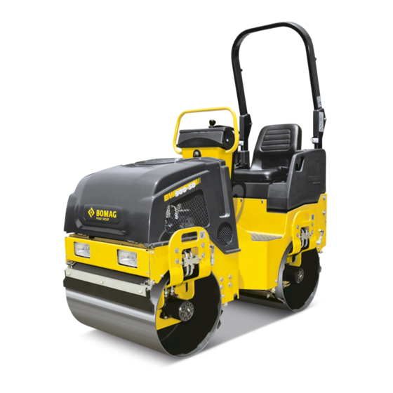
- Page 1 Operating Instruction Maintenance Instruction Original Operating Instructions BW 900-50 S/N 861 834 07 1001> / S/N 101 834 51 1001> Tandem vibratory roller www.discount-equipment.com 008 069 81 © 08/2018...
- Page 2 Discount-Equipment.com is your online resource for quality parts & equipment. Florida: 561-964-4949 Outside Florida TOLL FREE: 877-690-3101 Need parts? Click on this link: http://www.discount-equipment.com/category/5443-parts/ choose one of the options to help get the right parts and equipment you are looking for.
- Page 3 WARNING: Breathing diesel engine exhaust exposes you to chemicals known to the State of California to cause cancer and birth defects or other reproductive harm. Always start and operate the engine in a well-ventilated area. If in an enclosed area, vent the exhaust to the outside. Do not modify or tamper with the exhaust system.
-
Page 4: Table Of Contents
Table of contents Table of contents Introduction............................5 1.1 Foreword............................6 1.2 Machine type plate and engine type plate.................. 8 Technical data............................9 Safety regulations..........................13 3.1 Signage............................22 Indicators and control elements......................29 4.1 Description..........................31 Operation............................. 37 5.1 Checks prior to start up......................38 5.2 Starting the engine........................ - Page 5 Table of contents 6.9 Every 2000 operating hours....................... 78 6.9.1 Changing the hydraulic oil......................78 6.9.2 Change the hydraulic oil filter..................... 79 6.9.3 Checking fuel lines and clamps....................80 6.10 As required..........................82 6.10.1 Water sprinkler system, maintenance in case of frost.............. 82 6.10.2 Engine conservation.........................
-
Page 6: Introduction
Introduction Introduction BW 900-50... -
Page 7: Foreword
Introduction – Foreword 1.1 Foreword BOMAG manufactures machines for earth, asphalt and refuse compaction, stabilizers/recyclers as well as planers and pavers. BOMAG’s vast experience in connection with state-of-the-art production and testing methods, such as lifetime tests of all important components and highest quality demands guar- antee maximum reliability of your machine. - Page 8 Introduction – Foreword In the course of technical development we reserve the right for technical modifications without prior notification. These operating and maintenance instructions are also available in other languages. Apart from that, you can also order the spare parts catalogue against the serial number of your machine.
-
Page 9: Machine Type Plate And Engine Type Plate
Introduction – Machine type plate and engine type plate 1.2 Machine type plate and engine type plate Please enter here: Machine type (1): Serial number (2): Fig. 1: Machine type plate (example) Engine type and engine number Please enter here: Engine type: Engine number: B-HON-0008... -
Page 10: Technical Data
Technical data Technical data BW 900-50... - Page 11 Technical data Dimensions Fig. 3 1223 1727 2290 1967 (48) (38) (18) (22) (68) (90) (10) (86) (1.2) (0.3) (35) Dimensions in millimetres (Dimensions in inch) Weights Max. operating weight 1200 (2646) (lbs) Operating weight (CECE) 1600 (3527) (lbs) Average static linear load (CECE) kg/cm (37.5) (pli)
- Page 12 Technical data Travel characteristics 0 - 8.7 Travel speed km/h (0 - 5.4) (mph) 0 - 4 Working speed with vibration km/h (0 - 2.5) (mph) Max. gradeability without/with vibration (soil dependent) 40/30 Drive Engine manufacturer Honda Type GX 630 Cooling system Number of cylinders Rated power SAE J 1349...
- Page 13 Technical data Exciter system Vibrating drum front Drive system hydrostatic Frequency (4200) (vpm) Amplitude 0.50 (0.020) (in) Centrifugal force (3372) (lbf) Water sprinkler system Type of sprinkling Pressure Filling capacities Fuel (gasoline) (gal us) Water (36) (gal us) BW 900-50...
-
Page 14: Safety Regulations
Safety regulations Safety regulations BW 900-50... - Page 15 Safety regulations General This BOMAG machine has been built in compliance with the latest technical standard and complies with the applicable regulations and technical rules. However, dangers for persons and property may arise from this machine, if: it is used for purposes other than the ones it is intended for, it is operated by untrained personnel, it is changed or converted in an unprofessional way, the safety instructions are not observed.
- Page 16 Safety regulations Remaining dangers, remaining Despite careful work and compliance with standards and regula- risks tions it cannot be ruled out that further dangers may arise when working with and handling the machine. Both the machine as well as all other system components comply with the currently valid safety regulations.
- Page 17 Safety regulations Notes on safety in the operating and maintenance instructions WARNING! Paragraphs marked like this highlight possible dan- gers for persons. NOTICE! Paragraphs marked like this highlight possible dan- gers for machines or parts of the machine. Paragraphs marked like this contain technical infor- mation for the optimal economical use of the machine.
- Page 18 Safety regulations The machine cannot be steered. Tow the machine only after having released the parking brake. Max. towing speed 1 km/h (0.6 mph), max. towing distance 500 m (0.3 mi). Checking the Roll Over Protective The frame of the machine must not be warped, bent or cracked in Structure (ROPS) the area of the ROPS fastening.
- Page 19 Safety regulations Do not take any loose objects with you or fasten them to the machine. On machines with roll over protection system you must always wear your seat belt! Starting Start and operate the machine only from the driver’s seat. For starting set all control levers to 'neutral position'.
- Page 20 Safety regulations Do not use the machine to transport persons. Stop the machine if you notice unusual noises or the development of smoke. Investigate the cause and have the fault corrected. Keep a sufficient distance to excavations and embankments and make sure that your work does not impair the stability of the machine.
- Page 21 Safety regulations Refuel only with the engine shut down. Do not refuel in closed rooms. No open fire, do not smoke. Monitor the entire refuelling process. Do not spill any fuel. Catch running out fuel, do not let it seep into the ground.
- Page 22 Safety regulations Changing hydraulic hoses Hydraulic hoses must be visually inspected at regular intervals. Hydraulic hoses must be immediately replaced if: the outer layer is damaged down to the inlay (e.g. chafing, cuts, cracks) the outer layer is brittle (formation of cracks in the hose mate- rial) the hose shows deformations in pressurized and depressurized condition, which do not comply with the genuine shape of the...
-
Page 23: Signage
Safety regulations – Signage Observe the applicable instructions when starting with an auxiliary battery. Dispose of old batteries according to regulations. Switch off the charging current before removing the charging clamps. Ensure sufficient ventilation, especially if the battery is to be charged in a closed room. - Page 24 Safety regulations – Signage GASOLINE BENZIN 008 330 05 Hydraulic Oil The engine exhaust of this product contains chemicals known to the state of California to cause cancer, birth defects or other productive harm. B-834-0013 Fig. 4 BW 900-50...
- Page 25 Safety regulations – Signage Warning sticker - Danger of being pulled in by cooling fan, and hot surface Follow operating instructions B-DEC-0197 Fig. 5 Warning sticker - Danger of crushing Fig. 6 Warning sticker - Warning of engine exhaust gases The engine exhaust of this product contains chemicals known to the state of California to cause cancer, birth...
- Page 26 Safety regulations – Signage Instruction sticker - Always wear your seat belt Fig. 9 Information sticker - Lashing point Fig. 10 Information sticker - Filler opening for hydraulic oil Hydraulic Oil B-DEC-0214 Fig. 11 Information sticker - Engine oil drain B-DEC-0211 Fig.
- Page 27 Safety regulations – Signage Information sticker - Lifting point Fig. 13 Information sticker - Choke control B-DEC-0295 Fig. 14 Information sticker - Travel lever control B-DEC-0296 Fig. 15 Operation sticker - Throttle lever Fig. 16 BW 900-50...
- Page 28 Safety regulations – Signage Information sticker - Lubrication nipple B-DEC-0297 Fig. 17 Information sticker - Gasoline GASOLINE BENZIN B-DEC-0298 Fig. 18 Information sticker - Travel lever control B-DEC-0299 Fig. 19 BW 900-50...
-
Page 29: Indicators And Control Elements
Indicators and control elements Indicators and control elements BW 900-50... - Page 30 Indicators and control elements Fig. 20 Rotary switch for working lights Charge control lamp Operating hour meter Fuel level warning light Rotary switch for sprinkling system Ignition switch Choke lever BW 900-50...
-
Page 31: Description
Indicators and control elements – Description Emergency stop push button Rotary switch for interval sprinkling 10 Push button for warning horn 11 Rotary switch for flashing beacon 12 Push button for vibration 13 Travel lever 14 Throttle lever 15 Parking brake lever Optional equipment 4.1 Description Optional equipment... - Page 32 Indicators and control elements – Description Fuel level warning lamp lights if fuel needs to be filled up Fig. 24 Rotary switch for sprinkling system Position Left Sprinkling off Position Right Sprinkling on Fig. 25 Ignition switch Position "P"/"0" Ignition off, key can be pulled out, engine off.
- Page 33 Indicators and control elements – Description NOTICE! Run the engine warm for a short while before starting work. Do not rev up a cold engine to high idle speed/full load speed. Do not shut down the engine all of a sudden from full load speed, but let it idle for about 2 minutes.
- Page 34 Indicators and control elements – Description Interval switch for pressure sprinkler system Position Left, stage 6 permanent sprinkling when pressure sprinkling is switched on Stage 5 5 seconds on, 2 seconds pause Stage 4 4 seconds on, 4 seconds pause Stage 3 4 seconds on, 8 seconds pause Stage 2...
- Page 35 Indicators and control elements – Description Position "0" Neutral position, service brake, the machine is automatically braked by the hydrostatic drive. Position "I" Forward travel without vibration Position "II" Reverse travel without vibration Position "III" Max. forward/reverse travel with vibra- tion Throttle lever Position "MAX"...
- Page 36 Indicators and control elements – Description (5) 25A (F148) Fuse control MESX (potential (6) 15A (F41) Flashing beacon (7) 15A (F06) Water sprinkling system (8) 20A (F100) Working head lights Main fuse WARNING! Fire hazard! Do not use fuses with higher ampere ratings and do not repair fuses with a piece of wire.
-
Page 37: Operation
Operation Operation BW 900-50... -
Page 38: Checks Prior To Start Up
Operation – Checks prior to start up 5.1 Checks prior to start up Before the everyday use or before a longer working period the fol- lowing tests and inspections must be performed. WARNING! Please observe strictly the safety regulations in the corresponding section of this instruction manual! Park the machine on ground as level as possible. -
Page 39: Starting The Engine
Operation – Starting the engine 5.2 Starting the engine WARNING! Wear your personal noise protection means (ear defenders) before starting operation. Start the engine only from the operator’s seat. NOTICE! In this chapter it is assumed that the operator is fully acquainted with the function of the different control elements on the machine. - Page 40 Operation – Starting the engine Set the throttle lever Ä Fig. 41 to position "MIN". Fig. 41 Check, whether the emergency stop switch Ä Fig. 42 is unlocked. Fig. 42 Turn the ignition key Ä Fig. 43 to position "I". NOTICE! Run the starting process for maximum 20 seconds without interruption and pause for a minute...
- Page 41 Operation – Starting the engine Slowly open the choke Ä Fig. 45. NOTICE! Run the engine warm for a short while before starting work. Do not rev up a cold engine to high idle speed/full load speed. Fig. 45 BW 900-50...
-
Page 42: Driving The Machine
Operation – Driving the machine 5.3 Driving the machine WARNING! Danger of accident! Wet and loose soils considerably reduce the ground adhesion of the machine on inclinations and slopes. Soil conditions and weather influences impair the gradability of the machine. Do not drive up and down inclinations which exceed the maximum gradability of the machine (see chapter "technical data"). - Page 43 Operation – Driving the machine NOTICE! When changing the travel direction hold the travel lever for a moment in "0"-position, until the machine has stopped, before actuating to the new travel direction. Fig. 48 Shift the travel lever Ä Fig. 48 slowly to the desired travel direction.
-
Page 44: Stopping The Machine, Operating The Parking Brake
Operation – Stopping the machine, operating the parking brake 5.4 Stopping the machine, operating the parking brake Shift the travel lever Ä Fig. 49 slowly to "0"-position. Fig. 49 Pull up the hand brake lever Ä Fig. 50. Fig. 50 BW 900-50... -
Page 45: Shutting Down The Engine
Operation – Shutting down the engine 5.5 Shutting down the engine Shift the travel lever Ä Fig. 51 slowly to "0"-position. Fig. 51 Pull up the hand brake lever Ä Fig. 52. Fig. 52 Set the throttle lever Ä Fig. 53 to position "MIN". NOTICE! Do not shut down the engine all of a sudden from full load speed, but let it idle for about 2 minutes. -
Page 46: Switching The Vibration On And Off
Operation – Switching the vibration on and off 5.6 Switching the vibration on and off WARNING! Risk of damage! When compacting with vibration you must check the effect of nearby buildings and underground supply lines (gas, water, sewage, electric power), if necessary stop compaction with vibration. - Page 47 Operation – Switching the vibration on and off Shift the travel lever (13) Ä Fig. 56 slowly to the desired travel direction to position "III". Fig. 56 Actuate the vibration push button (12). Switching off vibration Actuate the vibration push button (12) again. BW 900-50...
-
Page 48: Switching The Pressure Sprinkling System On And Off
Operation – Switching the pressure sprinkling system on and off 5.7 Switching the pressure sprinkling system on and off Turn the rotary switch for pressurized sprinkling Ä Fig. 57 "clockwise" to switch on. Fig. 57 Set the interval switch Ä Fig. 58 to the desired sprinkling interval. -
Page 49: Towing
Operation – Towing 5.8 Towing WARNING! Danger of accident! Before releasing the parking brake secure the machine against unintended rolling by using appro- priate means (e.g. metal wheel chocks). Use a towing vehicle with sufficient traction and braking power for the unbraked towed load. Use a tow bar. - Page 50 Operation – Towing After towing WARNING! Danger of accident! Before loosening the drawbar secure the machine against unintended rolling by using appropriate means (e.g. metal wheel chocks), or apply the parking brake. BW 900-50...
-
Page 51: Loading And Transport
Operation – Loading and transport 5.9 Loading and transport WARNING! Danger of accident! Life hazard! Use only stable loading ramps of sufficient load bearing capacity. Make sure that persons are not endangered by the machine tipping or sliding off. Always use shackles on the lifting points for loading or tying the machine down. - Page 52 Operation – Loading and transport Lash the machine to the transport vehicle, use the lashing eyes Ä Fig. 63 on front and rear frame for this purpose. Fig. 63 Loading Use the central lifting facility Ä Fig. 64 to lift the machine. Fig.
- Page 53 Operation – Loading and transport Loosen the eye bolts Ä Fig. 66 and adjust the clamping plates vertically. Fig. 66 Fold the foldable ROPS back. Fold back up after transport WARNING! Life hazard! Operate the machine only with the ROPS folded up and the fastening screws tightened with the cor- rect tightening torque.
-
Page 54: Maintenance
Maintenance Maintenance BW 900-50... -
Page 55: General Notes On Maintenance
Maintenance – General notes on maintenance 6.1 General notes on maintenance When performing maintenance work always comply with the appro- priate safety regulations. Thorough maintenance of the machine guarantees far longer safe functioning of the machine and prolongs the lifetime of important components. - Page 56 Maintenance – General notes on maintenance The rest in the drum is not suitable for the engine and should only be used for cleaning purposes. Notes on the performance of the On engines both combustion air and fuel injection quantities are engine thoroughly adapted to each other and determine power, tempera- ture level and exhaust gas quality of the engine.
-
Page 57: Fuels And Lubricants
Maintenance – Fuels and lubricants 6.2 Fuels and lubricants Engine oil Quality The oil is an essential factor for the performance and lifetime of the engine. Use engine oil for four-stroke engines which meets or even exceeds the requirements for API-service class SJ or higher (or equivalent). - Page 58 Maintenance – Fuels and lubricants Lubrication grease For lubrication purposes use an EP-high pressure grease, lithium saponified (penetration 2), acc. to DIN 51502 KP 2G. BW 900-50...
-
Page 59: Table Of Fuels And Lubricants
Maintenance – Table of fuels and lubricants 6.3 Table of fuels and lubricants Assembly Fuel or lubricant Quantity Summer Winter Attention Observe the level marks motor - Engine oil Engine oil API SJ or higher approx. 0.5 gal (approx. 1.9 l) SAE 5W-30 (-4 °F to +86 °F) (-20 °C to +30 °C) SAE 10W-30 (5 °F to +86 °F) -
Page 60: Running-In Instructions
Maintenance – Running-in instructions 6.4 Running-in instructions The following maintenance work must be performed when running in new machines or overhauled engines: NOTICE! Up to approx. 250 operating hours check the engine oil level twice every day. Depending on the load the engine is subjected to, the oil consumption will drop to the normal level after approx. -
Page 61: Maintenance Table
Maintenance – Maintenance Table 6.5 Maintenance Table Maintenance works Page Every 10 operating hours 6.6.1 Checking the engine oil level 6.6.2 Checking the fuel level 6.6.3 Checking the hydraulic oil level 6.6.4 Checking the hydraulic oil filter element 6.6.5 Checking the water level 6.6.6 Cleaning the scrapers 6.6.7... -
Page 62: Every 10 Operating Hours
Maintenance – Every 10 operating hours 6.6 Every 10 operating hours 6.6.1 Checking the engine oil level NOTICE! The machine must be in horizontal position. For quality of oil refer to the "table of fuels and lubricants". Start the engine and run it 1 to 2 minutes with idle speed. Shut the engine down and wait 2 to 3 minutes. - Page 63 Maintenance – Every 10 operating hours Refuelling WARNING! Fire hazard! When working on the fuel system do not use open fire, do not smoke, do not spill any fuel. Do not refuel in closed rooms. Shut down the engine. WARNING! Health hazard! Do not inhale any fuel fumes.
-
Page 64: Checking The Hydraulic Oil Level
Maintenance – Every 10 operating hours 6.6.3 Checking the hydraulic oil level NOTICE! If, during the daily inspection of the oil level the hydraulic oil level is found to have dropped, check all lines, hoses and components for leaks. In hydraulic systems filled with Panolin Synth. 46 use only the same oil to top up. -
Page 65: Checking The Water Level
Maintenance – Every 10 operating hours 6.6.5 Checking the water level NOTICE! If there is a risk of frost observe the special service instructions in chapter "water sprinkler system, maintenance in case of frost". Make sure that the ventilation bore in the filler cap is free. -
Page 66: Cleaning The Cooling Air Intake Openings
Maintenance – Every 10 operating hours 6.6.7 Cleaning the cooling air intake openings NOTICE! Dirt in the cooling air intake openings reduces the cooling effect. Clean the cooling air intake openings Ä Fig. 78. Fig. 78 BW 900-50... -
Page 67: Every 125 Operating Hours
Maintenance – Every 125 operating hours 6.7 Every 125 operating hours 6.7.1 Check, clean the air filter, replace if necessary NOTICE! A dirty oil filter obstructs the air flow to the carbu- rettor, which then reduces the engine power. In a dusty environment you should clean the air filter every day. -
Page 68: Clean, Check The Spark Plugs, Replace If Necessary
Maintenance – Every 125 operating hours WARNING! Eye injury! Wear safety goggles. NOTICE! Do not hold the compressed air nozzle closer to the filter than 1 in (3 cm) Fig. 81 Bang the paper filter element several times against a hard surface. - Page 69 Maintenance – Every 125 operating hours NOTICE! Renew the spark plugs at the latest after 250 oper- ating hours or once every year. Pull off the spark plug socket (1) Ä Fig. 83 and clean off any dirt in the spark plug area. Unscrew the spark plug with a spark plug spanner (2).
-
Page 70: Changing Engine Oil And Oil Filter
Maintenance – Every 125 operating hours 6.7.3 Changing engine oil and oil filter WARNING! Danger of scalding! When draining off hot oil. By hot oil when unscrewing the engine oil filter. NOTICE! Drain the engine oil only when the engine is warm. For quality and quantity of oil refer to the "table of fuels and lubricants". -
Page 71: Lubricating The Rear Drum Bearings
Maintenance – Every 125 operating hours Fill in new engine oil Ä Fig. 87. Screw the oil filler cover back on again. After a short test run check the oil level once again , if neces- sary top up to the top mark (Max). Fig. -
Page 72: Every 250 Operating Hours
Maintenance – Every 250 operating hours 6.8 Every 250 operating hours 6.8.1 Change the fuel pre-filter WARNING! Fire hazard! When working on the fuel system do not use open fire, do not smoke, do not spill any fuel. WARNING! Health hazard! Do not inhale any fuel fumes. -
Page 73: Battery Service
Maintenance – Every 250 operating hours Unscrew the cap nut of the hose Ä Fig. 90. Unscrew and clean the water filter. Flush the water tank thoroughly. Screw the water filter back in, tighten the cap nut again. Fig. 90 Loosen hose clamp (1) Ä... - Page 74 Maintenance – Every 250 operating hours Maintenance free batteries also need care. Mainte- nance free only means that the fluid level does not need to be checked. Each battery suffers under self-discharge, which may, in not checked occa- sionally, even cause damage to the battery as a result of exhaustive discharge.
-
Page 75: Checking, Adjusting The Valve Clearance
Maintenance – Every 250 operating hours 6.8.4 Checking, adjusting the valve clearance NOTICE! We recommend to have this work carried out by trained personnel or our after sales service. Check and adjust only when the engine is cold. Adjusting values intake valves: 0.0031 in ±... -
Page 76: Check, Adjust The Idle Speed
Maintenance – Every 250 operating hours Turn the flywheel clockwise further Ä Fig. 96, until the marks (2, 3) are in line. Check and , if necessary, adjust the valve clearance of the 2nd cylinder. After checking and adjusting reassemble the cylinder head covers with new gaskets. -
Page 77: Every 2000 Operating Hours
Maintenance – Every 2000 operating hours 6.9 Every 2000 operating hours 6.9.1 Changing the hydraulic oil See also the notes on the hydraulic system in the chapter "General notes on maintenance". WARNING! Danger of scalding! When draining off hot hydraulic oil! NOTICE! The hydraulic oil must also be changed after major repairs in the hydraulic system. -
Page 78: Change The Hydraulic Oil Filter
Maintenance – Every 2000 operating hours Remove the cap from the hydraulic oil tank Ä Fig. 98. Fig. 98 Unscrew the plug from the hydraulic oil tank Ä Fig. 99, drain off and collect all hydraulic oil. Turn the plug tightly back in. We recommend to use our filling and filtering unit with fine filter to fill the system. -
Page 79: Checking Fuel Lines And Clamps
Maintenance – Every 2000 operating hours NOTICE! If the filter has to be changed together with the hydraulic oil, the filter must only be changed after the oil change and after the test run. Do not use the oil in the filter bowl again. Visible dirt may be an early sign for the failure of system components and indicate the possible failure of components. - Page 80 Maintenance – Every 2000 operating hours NOTICE! If fuel lines or hose clamps are found to be dam- aged, the corresponding parts must be immedi- ately repaired or replaced. After replacing lines or hose clamps the fuel system needs to be bled. Disassembled or new fuel lines must be closed with clean cloths on both ends, to make sure that no dirt will enter into the fuel system.
-
Page 81: As Required
Maintenance – As required 6.10 As required 6.10.1 Water sprinkler system, maintenance in case of frost NOTICE! If there is a risk of frost the water sprinkler system must be emptied or filled with an anti-freeze mix- ture. Drain off all water. Switch the sprinkler system on and drain all water from the piping. - Page 82 Maintenance – As required Remove the cylinder head covers, spray the rocker cham- bers with anti-corrosion oil. Then fasten the covers again. Unscrew both spark plugs and spray anti-corrosion oil through the spark plug openings. Crank the engine several times and install the spark plugs again. Close air intake on air filter and exhaust opening tightly.
-
Page 83: Troubleshooting
Troubleshooting Troubleshooting BW 900-50... -
Page 84: Preliminary Remarks
Troubleshooting – Preliminary remarks 7.1 Preliminary remarks Malfunctions are frequently caused by incorrect operation of the machine or insufficient maintenance. Whenever a fault occurs you should therefore thoroughly read these instructions on correct operation and maintenance. If you cannot locate the cause of a fault or rectify it yourself by fol- lowing the trouble shooting chart, you should contact our customer service department. -
Page 85: Starting The Engine With Jump Leads
Troubleshooting – Starting the engine with jump leads 7.2 Starting the engine with jump leads NOTICE! A wrong connection will cause severe damage in the electric system. – Bridge the machine only with a 12 Volt auxiliary battery. Connect the plus pole of the external battery first with the plus pole of the vehicle battery using the first jump lead. -
Page 86: Engine Problems
Troubleshooting – Engine problems 7.3 Engine problems Fault description Cause Remedy Engine does not start Fuel tank empty Fill fuel tank Fuel filter clogged Change the filter Fuel lines leaking Check all line connections for leaks and tighten the fittings Emergency stop switch Unlock the emergency stop switch locked... - Page 87 Troubleshooting – Engine problems Fault description Cause Remedy Engine overheating, engine must be Cooling air inlets heavily Clean the cooling air inlets shut down immediately! soiled Air filter dirty Clean air filter, change if necessary BW 900-50...
-
Page 88: Disposal
Disposal Disposal BW 900-50... -
Page 89: Final Shut-Down Of Machine
Disposal – Final shut-down of machine 8.1 Final shut-down of machine If the machine can no longer be used and needs to be finally shut down you must carry out the following work and have the machine disassembled by an approved specialist workshop. ENVIRONMENT! Catch all fuels and lubricants, do not let them seep into the ground and dispose of in compliance with... - Page 90 Discount-Equipment.com is your online resource for quality parts & equipment. Florida: 561-964-4949 Outside Florida TOLL FREE: 877-690-3101 Need parts? Click on this link: http://www.discount-equipment.com/category/5443-parts/ choose one of the options to help get the right parts and equipment you are looking for.
Need help?
Do you have a question about the BOMAG BW 900-50 and is the answer not in the manual?
Questions and answers