Advertisement
Quick Links
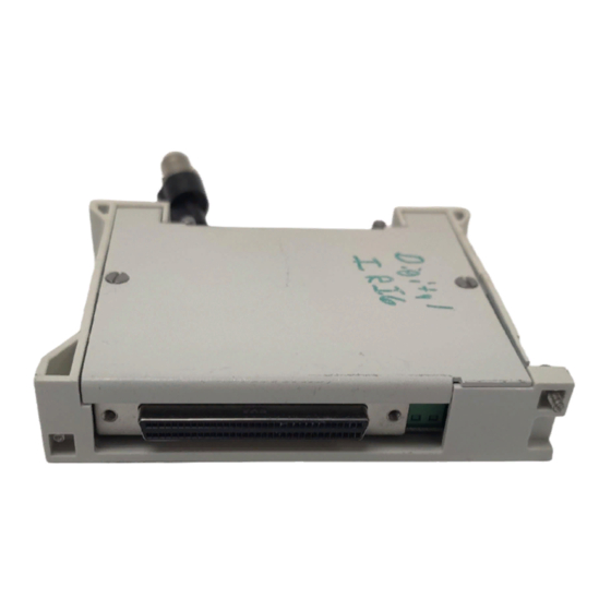
INSTALLATION GUIDE
TB-2715 T
What You Need to Get Started
Connecting Signals to Your Terminal Block
™
™
National Instruments
, ni.com
trademarks or trade names of their respective companies.
322984A-01
B
ERMINAL
This installation guide describes how to install and connect signals to the
TB-2715 terminal block for use with PXI-653X and PXI-660X modules.
Use the TB-2715 terminal block to connect to the signals of a PXI-653X or
PXI-660X module. Connect your signals to the screw terminals housed in
the terminal block then install the TB-2715 to the PXI front panel.
To set up and use the TB-2715, you will need the following:
❑
TB-2715 terminal block
❑
Quick-reference labels for PXI-653X and PXI-660X
❑
One of the following:
–
PXI-653X module
–
PXI-660X module
❑
653X User Manual or 660X User Manual
❑
0.10 in. slotted screwdriver
❑
Number 1 Phillips screwdriver
❑
Wire cutters
❑
Wire insulation stripper
Refer to Figure 1 as you perform the following steps to connect signals
from the peripheral device to the TB-2715. For more information about
connecting signals to your terminal block, see your 653X User Manual or
660X User Manual.
™
, and PXI
are trademarks of National Instruments Corporation. Product and company names mentioned herein are
© Copyright 2000 National Instruments Corp. All rights reserved.
LOCK
December 2000
Advertisement

Related Manuals for National Instruments TB-2715


Summary of Contents for National Instruments TB-2715
- Page 1 This installation guide describes how to install and connect signals to the TB-2715 terminal block for use with PXI-653X and PXI-660X modules. Use the TB-2715 terminal block to connect to the signals of a PXI-653X or PXI-660X module. Connect your signals to the screw terminals housed in the terminal block then install the TB-2715 to the PXI front panel.
- Page 2 3 Strain-Relief Bar 6 Strain-Relief Screws 9 Chassis Ground Tab Figure 1. TB-2715 Parts Locator Diagram Remove the terminal block cover by unscrewing the two cover screws using the 0.10 in. slotted screwdriver. Apply the appropriate quick reference label to the inside of the top cover as shown in Figure 2.
- Page 3 7 mm of insulation from the wire ends. Use Figures 3 and 4 to find the 653X and 660X signals that correspond to the screw terminals on the TB-2715. Please note that lines 19, 35, 43, and 56 are not connected.
- Page 4 PFI_13(UP_DOWN_6) PFI_27(SOURCE_3) PFI_0(DIO_0) PFI_14(GATE_6) PFI_1(DIO_1) PFI_28(OUT_2) PFI_15(SOURCE_6) PFI_29(UP_DOWN_2) PFI_2(DIO_2) PFI_16(OUT_5) PFI_3(DIO_3) PFI_30(GATE_2) PFI_31(SOURCE_2) PFI_4(DIO_4) Figure 4. Pinout Diagram for PXI-660X Modules Loosen the screws in the screw terminals with the 0.10 in. slotted screwdriver. TB-2715 Terminal Block Installation Guide ni.com...
- Page 5 Guide the terminal block onto the module connector. Tighten the two terminal block mounting screws. Insert the terminal block as shown in Figure 5. The TB-2715 can be attached to a Caution PXI module only one way. Do not force the terminal block when attaching or removing it to avoid damaging the TB-2715 or PXI module.
Need help?
Do you have a question about the TB-2715 and is the answer not in the manual?
Questions and answers