Table of Contents
Advertisement
Quick Links
Office: (800) 683-7248
Technical Support: (702) 651-3444
FAX: (702) 651-0214
E-Mail: techsupport@jcm-american.com
Web-Site: www.jcm-american.com
®
WBA
Series
World Bill Acceptor
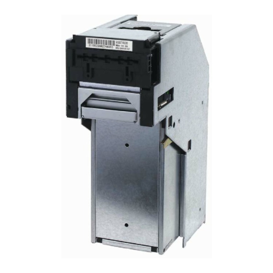
ID =WBABack+Pix+R.jpg
(WBA-1x/2x -SS & SS2)
Operation and Maintenance Manual
(Revision 1)
JCM Part No. 960-000076R_Rev. 1
© 2007, JCM American, Corporation
Advertisement
Table of Contents

Related Manuals for JCM WBA Series

Summary of Contents for JCM WBA Series
- Page 1 Office: (800) 683-7248 Technical Support: (702) 651-3444 FAX: (702) 651-0214 E-Mail: techsupport@jcm-american.com Web-Site: www.jcm-american.com ® Series World Bill Acceptor ID =WBABack+Pix+R.jpg (WBA-1x/2x -SS & SS2) Operation and Maintenance Manual (Revision 1) JCM Part No. 960-000076R_Rev. 1 © 2007, JCM American, Corporation...
- Page 2 JCM is a registered trademark of JCM American Corporation. All other product names mentioned herein may be ™ ® © registered trademarks or trademarks of their respective companies. Furthermore, are not always mentioned in each case throughout this publication.
-
Page 3: Table Of Contents
Transport CPU Circuit Board Removal..................4-3 Stacker Encoder Sensor Board Removal..................4-4 Stacker Motor Removal ......................4-5 Transport Encoder Sensor Board Removal................4-5 Transport Drive Motor Removal ....................4-5 Entrance Lever Sensor Board Removal..................4-5 Solenoid Lever Assembly Removal...................4-6 JCM Part No. 960-000076R_Rev. 1 © 2007, JCM-American Corporation... - Page 4 WBA Cash Box Unit Exploded View (Continued) ..............7-18 8 INDEX ........................8-1 A TROUBLESHOOTING ..................A-1 Introduction ......................... A-1 Troubleshooting Overview ..................A-1 Fault Table Listings..................... A-1 Performance Tests ...................... A-4 Choosing and Selecting Operational Tests................A-4 JCM Part No. 960-000076R_Rev. 1 © 2007, JCM-American Corporation...
- Page 5 Table A-10 lists the WBA-1X/2X Abnormal Operation Codes.......A-11 Test Mode 4 Only Error Table ...................A-11 Table A-11 lists the WBA-1X/2X Abnormal Operation Codes........A-11 Return Code Error Table ...................A-12 B GLOSSARY......................B-1 JCM Part No. 960-000076R_Rev. 1 © 2007, JCM-American Corporation i i i...
- Page 6 WBA® 1x/2x-SS & SS2 Series Table of Contents THIS PAGE INTENTIONALLY LEFT BLANK JCM Part No. 960-000076R_Rev. 1 © 2007, JCM-American Corporation...
- Page 7 Figure 2-13 Clearing a Transport Unit Bill Jam............2-7 Figure 2-14 Clearing a Cash Box Inlet Bill Jam ............2-8 Figure 2-15 Cleaning the WBA Bill Path ..............2-8 Figure 2-16 JCM Waffletechnology Cleaning Card..........2-8 Figure 2-17 WBA Bill Acceptor Operational Flowchart ..........2-9 Figure 4-1 WBA Acceptor Head Removal .............
- Page 8 White Calibration Occurring Screen ............. 6-3 Figure 6-9 Black Paper Calibration Screen............6-3 Figure 6-10 Black Calibration Paper Types ............. 6-3 Figure 6-11 Inserting Black Calibration Paper ............6-3 Figure 6-12 Black Calibration Occurring Screen............6-3 JCM Part No. 960-000076R_Rev. 1 © 2007, JCM-American Corporation...
- Page 9 Figure A-2 WBA 2X Head Sensor Locations............A-7 Figure A-3 WBA-1X/2X Transport Sensor Locations ..........A-8 Figure A-4 WBA-1X/2X Sensor, Circuit Board and Motor Location Diagram ..A-8 JCM Part No. 960-000076R_Rev. 1 © 2007, JCM-American Corporation v i i...
-
Page 10: Jcm Part No. 960-000076R_Rev
WBA® 1x/2x-SS & SS2 Series List of Figures THIS PAGE INTENTIONALLY LEFT BLANK JCM Part No. 960-000076R_Rev. 1 © 2007, JCM-American Corporation v i i i... - Page 11 WBA-1X/2X Forced Download Mode Chart.......... A-9 Table A-10 WBA-1X/2X Abnormal Operation Code Table ........A-11 Table A-11 WBA-1X/2X Test Mode 4 Abnormal Operation Code Table ....A-11 Table A-12 WBA-1X/2X Return Error Code Table ..........A-12 JCM Part No. 960-000076R_Rev. 1 © 2007, JCM-American Corporation...
- Page 12 WBA® 1x/2x-SS & SS2 Series List of Tables THIS PAGE INTENTIONALLY LEFT BLANK JCM Part No. 960-000076R_Rev. 1 © 2007, JCM-American Corporation...
-
Page 13: General Information
Complete Unit Dimensions specific actions are given sequential numbers • Unit Dimensions with WBA Faceplate (1., 2., 3., etc.) • Unit Dimensions with ICB World Bill Acceptor WBA-1x-SS) Figure 1-1 JCM Part No. 960-000076R_Rev. 1 © 2007, JCM-American Corporation 1 - 1... -
Page 14: Model Number Specifications
0 = Without Faceplate (standard) environment. 1 = With JCM standard WBA Faceplate (85mm wide) (8) Guide Width 5. Do not throw the unit or allow it to fall to the 1 = 66mm 4 = 80mm ground. -
Page 15: Component Names
General Information World Bill Acceptor (WBA®-1x/2x-SS & SS2) Section 1 A new JCM authorized Waffletechnology further information concerning its avail- Cleaning Card is now available. Refer to ability and use. “Cleaning/Preventive Maintenance” on 7. Inserting worn or damaged bills may also page 8 of Section 2 of this manual for cause a bill jam. -
Page 16: Specifications
Approximately 10.582 lbs (~4.8kg) Cash Box Weight Approximately 3.307 lbs (~1.5kg empty) Mounting: Horizontal Outer Dimensions: 11.96 in (303.8mm) High x 8.86 in (225mm) Deep x 4.49 in (114mm) Wide JCM Part No. 960-000076R_Rev. 1 © 2007, JCM-American Corporation 1 - 4... -
Page 17: System Configuration
Figure 1-4 WBA System Configuration Primary Features • DIP Switch Programmable Bill Acceptance – DIP switch settings to accept/reject bills The WBA Series of Bill Validators contains the following primary features: – Up to 7 denominations acceptable. • – Interchangeable Bill Guides Accept or Reject of each denomination is DIP Switch selectable. -
Page 18: Standard Unit Dimensions
General Information Standard Unit Dimensions Figure 1-7 illustrates the WBA-1x-SS standard unit dimensions. NOTE: All Units are in Millimeters. Figure 1-7 Bill Acceptor WBA-1x-SS Complete Unit Dimensions Diagram JCM Part No. 960-000076R_Rev. 1 © 2007, JCM-American Corporation 1 - 6... -
Page 19: Country Codes
Poland POL1-B Great Britain/Isle Of Man GBR/MAN Portugal Greece Qatar Greece GRC-B Republic Of Ireland Guatemala Republic Of Korea Honduras Republic Of Korea KOR-B Hong Kong Romania Hungary JCM Part No. 960-000076R_Rev. 1 © 2007, JCM-American Corporation 1 - 7... - Page 20 UKR1 United Arab Emirates United States Uruguay Uruguay URY1 Venezuela Venezuela VEN1 Venezuela VEN2 Venezuela VEN-B These Country Codes conform to the ISO 3166 Country Code list definitions. JCM Part No. 960-000076R_Rev. 1 © 2007, JCM-American Corporation 1 - 8...
-
Page 21: Installation/Operation
2. Push the bill guides out from the back of the Figure 2-1 Right Side Panel Dip Switch Block Acceptor Head section with a Flat-blade Screwdriver (See Figure 2-3). JCM Part No. 960-000076R_Rev. 1 © 2007, JCM-American Corporation 2 - 1... -
Page 22: Input/Output Circuits
Figure 2-5 WBA 12, 13, 22 & 23 Input/Output Circuit Diagram Figure 2-6 WBA 10, 11, 20 & 21 Input/Output Circuit Diagram JCM Part No. 960-000076R_Rev. 1 © 2007, JCM-American Corporation 2 - 2... -
Page 23: Connector Pin Assignments
12 NC Reserved (No Connection) *. I/O (input/output) is the terminal viewed from Bill Acceptor’s side. †. Signal name, I/O, and function without parenthesis are for ID-003 interface. JCM Part No. 960-000076R_Rev. 1 © 2007, JCM-American Corporation 2 - 3... -
Page 24: Table 2-5 Wba-12/13,22&23-Ss2 20 Pin Rear Panel Connector Pin
20 NC Reserved (No Connection) *. I/O (input/output) is the terminal viewed from Bill Acceptor’s side. †. Signal name, I/O, and function without parenthesis are for ID-003 interface. JCM Part No. 960-000076R_Rev. 1 © 2007, JCM-American Corporation 2 - 4... -
Page 25: Cable Interconnection
Figure 2-7 Typical WBA 1X/2X SS Cabling Requirements Figure 2-8 illustrates the typical cabling requirements between the Host Machine and a 1X/2X SS2 Bill Figure 2-8 Typical WBA 1X/2X SS2 Cabling Requirements JCM Part No. 960-000076R_Rev. 1 © 2007, JCM-American Corporation 2 - 5... -
Page 26: Dip Switch Configurations
$1 bill disabled $1 bill enabled local JCM Customer Representative for the $5 bill disabled $5 bill enabled latest setting information, or visit the JCM $10 bill disabled $10 bill enabled Website at www.jcm-american.com. $20 bill disabled $20 bill enabled WBA-1X and WBA-2X Head Sensor Lens Differences Figure 2-9 illustrates the WBA 1x-SS and 2X-SS Acceptor Head Lens Differences. -
Page 27: Retrieving Bills
3. Remove the jammed bill (See Figure 2-12 4. If the jammed bill cannot be removed by opening the Acceptor, pull up on the Transport Unit Open/Close Lever (See Figure 2-13 a) JCM Part No. 960-000076R_Rev. 1 © 2007, JCM-American Corporation 2 - 7... -
Page 28: Cleaning/Preventive Maintenance
Section 2 World Bill Acceptor (WBA®-1x/2x-SS & SS2) Installation/Operation Available Cleaning Card A second generation JCM Waffletechnology Bill Validator Cleaning Card is now available (JCM 501-000141R Part No. )(Manufacturer’s Part No. KWJCM-B2B15M). The cleaning card is designed to be used as a supplemental part of a Preventive Maintenance program to help in reducing dirt and paper dust build-up within a unit. -
Page 29: Id-003 Standard Interface Operational Flowchart
World Bill Acceptor (WBA®-1x/2x-SS & SS2) Section 2 ID-003 Standard Interface Operational Flowchart Figure 2-17 depicts a typical ID-003 Interface WBA bill acceptance flow process. Figure 2-17 WBA Bill Acceptor Operational Flowchart JCM Part No. 960-000076R_Rev. 1 © 2007, JCM-American Corporation 2 - 9... - Page 30 Section 2 World Bill Acceptor (WBA®-1x/2x-SS & SS2) Installation/Operation THIS PAGE INTENTIONALLY LEFT BLANK JCM Part No. 960-000076R_Rev. 1 © 2007, JCM American, Corporation 2 - 1 0...
-
Page 31: Communications
This section was intentionally left out due to a Non Disclosure Agreement requirement. If this information is required, please contact: JCM Technical Support 925 Pilot Road Las Vegas, Nevada 89119 (702) 651-0000 JCM Part No. 960-000076R_Rev. 1 © 2007, JCM-American Corporation 3 - 1... - Page 32 World Bill Acceptor (WBA®-1x/2x -SS & SS2) THIS PAGE INTENTIONALLY LEFT BLANK JCM Part No. 960-000076R_Rev. 1 © 2007, JCM-American Corporation 3 - 2...
-
Page 33: Disassembly/Reassembly
Latch (See Figure 4-1 a) and pull the WBA Acceptor assembly forward and out of the unit (See Figure 4-1 b). Figure 4-3 WBA Unit Cash Box Removal Figure 4-1 WBA Acceptor Head Removal JCM Part No. 960-000076R_Rev. 1 © 2007, JCM-American Corporation 4 - 1... -
Page 34: Acceptor Unit Disassembly
(See Figure 4-7 b) and lift the board up and off the unit. Figure 4-5 WBA Acceptor’s Upper Sensor Board Figure 4-7 WBA Acceptor’s Lower Sensor Board Removal Removal JCM Part No. 960-000076R_Rev. 1 © 2007, JCM-American Corporation 4 - 2... -
Page 35: Belt Tension Assembly Removal
(See Figure 4-9 b). from the Transport’s CPU Circuit Board (See Figure 4-11). Figure 4-9 Acceptor Head Drive Belt Assembly Figure 4-11 WBA 10/11 CPU Board Removal Removal JCM Part No. 960-000076R_Rev. 1 © 2007, JCM-American Corporation 4 - 3... -
Page 36: Stacker Encoder Sensor Board Removal
(See Figure 4-16 b). of the housing (See Figure 4-14 a), and remove the single (1) screw securing the Val- idator Catch Bar to remove its beam (See Figure 4-14 b). JCM Part No. 960-000076R_Rev. 1 © 2007, JCM-American Corporation 4 - 4... -
Page 37: Stacker Motor Removal
Transport Assembly (See Figure 4-18 b) and Transport Assembly (See Figure 4-20 b) and 4. Disconnect the harness plug from the Encoder Sensor Board to remove it from the assembly (See Figure 4-18 c). JCM Part No. 960-000076R_Rev. 1 © 2007, JCM-American Corporation 4 - 5... -
Page 38: Solenoid Lever Assembly Removal
Assembly, and remove the shaft (See Figure from the assembly (See Figure 4-22 a & b). 4-24 a, b & c). JCM Part No. 960-000076R_Rev. 1 © 2007, JCM-American Corporation 4 - 6... -
Page 39: Feed-Out Sensor Assembly Removal
1. Remove the four (4) Home Position Sensor Figure 4-25 Transport Feed-Out Sensor Board mounting screws located on each side Assembly Removal of the housing (See Figure 4-28 a). JCM Part No. 960-000076R_Rev. 1 © 2007, JCM-American Corporation 4 - 7... -
Page 40: Upper Timing Belt Removal Continuation
Figure 4-29 Transport Timing Belt Removal bushing on the second inside shaft Figure 4-8 better illustrates a complete Transport (See Figure 4-31 c). Timing Belt Shaft component disassembly. JCM Part No. 960-000076R_Rev. 1 © 2007, JCM-American Corporation 4 - 8... -
Page 41: Cash Box Disassembly
Figure 4-35 Coupling Bracket Handle Removal 2. Remove the two (2) Drive Gear securing E-rings and lift the two gears from their Figure 4-33 Pusher Mechanism Removal respective shafts (See Figure 4-36 a). JCM Part No. 960-000076R_Rev. 1 © 2007, JCM-American Corporation 4 - 9... -
Page 42: Figure 4-36 Pusher Mechanism Gear Removal
Figure 4-37 Pusher Mechanism Belt Removal The WBA Disassembly Procedure is now complete. Reverse all of the proceeding instructions to reassemble any of the components described during this disassembly procedure. JCM Part No. 960-000076R_Rev. 1 © 2007, JCM-American Corporation 4 - 1 0... -
Page 43: Wiring Diagrams
WBA-24-SS3B System Wiring Diagram parts lists for the following items: • WBA-25-SS3B System Wiring Diagram • WBA Primary Components WBA Primary Components Diagram Figure 5-1 World Bill Acceptor (WBA) Primary Components JCM Part No. 960-000076R_Rev. 1 © 2007, JCM-American Corporation 5 - 1... - Page 44 Section 5 World Bill Acceptor (WBA®-1x/2x -SS & SS2) Wiring Diagrams THIS PAGE INTENTIONALLY LEFT BLANK JCM Part No. 960-000076R_Rev. 1 © 2007, JCM American, Corporation 5 - 2...
-
Page 45: Figure 5-2 Wba-14-Ss3B Bill Acceptor System Wiring Diagram
Wiring Diagrams World Bill Acceptor (WBA®-1x/2x -SS & SS2) Section 5 WBA-14-SS3B System Wiring Diagram Figure 5-2 WBA-14-SS3B Bill Acceptor System Wiring Diagram JCM Part No. 960-000076R_Rev. 1 © 2007, JCM American, Corporation 5 - 3... -
Page 46: Figure 5-3 Wba-15-Ss3B Bill Acceptor System Wiring Diagram
Section 5 World Bill Acceptor (WBA®-1x/2x -SS & SS2) Wiring Diagrams WBA-15-SS3B System Wiring Diagram Figure 5-3 WBA-15-SS3B Bill Acceptor System Wiring Diagram JCM Part No. 960-000076R_Rev. 1 © 2007, JCM American, Corporation 5 - 4... -
Page 47: Figure 5-4 Wba-24-Ss3B Bill Acceptor System Wiring Diagram
Wiring Diagrams World Bill Acceptor (WBA®-1x/2x -SS & SS2) Section 5 WBA-24-SS3B System Wiring Diagram Figure 5-4 WBA-24-SS3B Bill Acceptor System Wiring Diagram JCM Part No. 960-000076R_Rev. 1 © 2007, JCM American, Corporation 5 - 5... -
Page 48: Figure 5-1 Wba-25-Ss3B Bill Acceptor System Wiring Diagram
Section 5 World Bill Acceptor (WBA®-1x/2x -SS & SS2) Wiring Diagrams WBA-25-SS3B System Wiring Diagram Figure 5-1 WBA-25-SS3B Bill Acceptor System Wiring Diagram JCM Part No. 960-000076R_Rev. 1 © 2007, JCM American, Corporation 5 - 6... -
Page 49: Calibration And Testing
S e c t i o n 6 6 CALIBRATION AND TESTING • The latest WBA Download Program CD (obtain from your JCM Sales Representative) This section provides Flash EPROM Memory • Black, White and Mag Tool Calibration Paper Download Programming, Calibration, and... -
Page 50: Software Downloading Procedure
White Calibration Paper (“KS-030” for WBA-12/13, “ADJ20Win_e.exe” for WBA- WBA-12/13 or “KS-032” for WBA-22/23/ 22/23/24/25). 24/25) as shown in Figure 6-6 and illustrated in Figure 6-7 a respectively. JCM Part No. 960-000076R_Rev. 1 © 2007, JCM-American Corporation 6 - 2... -
Page 51: Figure 6-6 White Calibration Paper Types
Figure 6-5 Screen the tabs on both side of the Acceptor Head will re-appear (See Figure 6-13). firmly lock in place (See Figure 6-11 b). JCM Part No. 960-000076R_Rev. 1 © 2007, JCM-American Corporation 6 - 3... -
Page 52: Figure 6-13 White Re-Calibration Request Screen
(i.e., no detected after the MAG Board has been calibration paper inserted). inserted. When calibration begins the Figure 6-16 Screen will appear. JCM Part No. 960-000076R_Rev. 1 © 2007, JCM-American Corporation 6 - 4... -
Page 53: Figure 6-19 Magnetic Adjust Value Screen
Figure 6-24 End Calibration Screen If another WBA Acceptor Head requires Figure 6-21 Adjusting Magnetic Gain Screen calibration, press the key and ENTER replace the current calibrated unit with a new JCM Part No. 960-000076R_Rev. 1 © 2007, JCM-American Corporation 6 - 5... -
Page 54: Calibration Error Messages
Name comparisons for the WBA-1X-SS Vali- dator, and Table 6-2 lists the Sensor Signal Name vs. its Sensor Name comparisons for the WBA-2X- SS Validator. JCM Part No. 960-000076R_Rev. 1 © 2007, JCM-American Corporation 6 - 6... -
Page 55: Exploded Views And Parts Lists
World Bill Acceptor Series (WBA). This section contains the following • Cash Box Unit View and Parts information: Entire WBA Unit View and Parts Figure 7-1 Entire WBA Unit Exploded View JCM Part No. 960-000076R_Rev. 1 © 2007, JCM-American Corporation 7 - 1... -
Page 56: Entire Wba Unit Parts List
843-05-03A Standard Interface Harness R 060455* 843-05-02A OEM Interface Harness R 046996 M3 X10 Screw with Washer It is a interim EDP#. Please contact JCM headquarters before you order. JCM Part No. 960-000076R_Rev. 1 © 2007, JCM-American Corporation 7 - 2... -
Page 57: Wba 12/13 Acceptor Head Exploded Views
Exploded Views and Parts Lists World Bill Acceptor (WBA®-1x/2x -SS & SS2) Section 7 WBA 12/13 Acceptor Head Exploded Views Figure 7-2 WBA 12/13 Acceptor Head Exploded View JCM Part No. 960-000076R_Rev. 1 © 2007, JCM-American Corporation 7 - 3... -
Page 58: Wba 22/23/24/25 Acceptor Head Exploded View
Section 7 World Bill Acceptor (WBA®-1x/2x -SS & SS2) Exploded Views and Parts Lists WBA 22/23/24/25 Acceptor Head Exploded View Figure 7-3 WBA 22/23/24/25 Acceptor Head Exploded View JCM Part No. 960-000076R_Rev. 1 © 2007, JCM-American Corporation 7 - 4... -
Page 59: Wba 12/13 & 22/23/24/25 Acceptor Head Collective Parts List
Guide D (MG) R WBA-12/13 054624 0943RE0104E Guide D (FOT) R WBA-22/23/24/25 052591 0943SH0107A HD Roller Shaft 052657 0943KS0103E HDR Spring 052507 0943RE0103D Guide C R 045854 CS-1 Coaching Clip* P JCM Part No. 960-000076R_Rev. 1 © 2007, JCM-American Corporation 7 - 5... - Page 60 E-Ring Ø2 Sustainer 054706 2.6x7 Pan W Sems Small 003708 E-Ring Ø4 Sustainer 046975 3X6 Pan W Sems Small 038938 2X10 Parallel Pin 040343 0943RE1008 (RE-7AJ03) Reflective Sensor WBA-22/23/24/25 JCM Part No. 960-000076R_Rev. 1 © 2007, JCM-American Corporation 7 - 6...
-
Page 61: Wba Transport Unit Exploded Views (Continued)
Exploded Views and Parts Lists World Bill Acceptor (WBA®-1x/2x -SS & SS2) Section 7 WBA Transport Unit Exploded Views (Continued) Figure 7-4 WBA Transport Unit Exploded View (Part 1) JCM Part No. 960-000076R_Rev. 1 © 2007, JCM American, Corporation 7 - 7... -
Page 62: Figure 7-5 Wba Transport Unit Exploded View (Part 2)
World Bill Acceptor (WBA®-1x/2x -SS & SS2) Exploded Views and Parts Lists WBA Transport Unit Exploded Views (Continued) Figure 7-5 WBA Transport Unit Exploded View (Part 2) JCM Part No. 960-000076R_Rev. 1 © 2007, JCM American, Corporation 7 - 8... -
Page 63: Wba Transport Unit Exploded Views (Continued)
Exploded Views and Parts Lists World Bill Acceptor (WBA®-1x/2x -SS & SS2) Section 7 WBA Transport Unit Exploded Views (Continued) Figure 7-6 WBA Transport Unit Exploded View (Part 3) JCM Part No. 960-000076R_Rev. 1 © 2007, JCM American, Corporation 7 - 9... - Page 64 World Bill Acceptor (WBA®-1x/2x -SS & SS2) THIS PAGE INTENTIONALLY LEFT BLANK JCM Part No. 960-000076R_Rev. 1 © 2007, JCM American, Corporation 7 - 1 0...
-
Page 65: Table 7-3 Wba Transport Unit Collective Parts List
R Pulley Shaft 2 WBA-SS 096732 0943SH0218 Pulley Shaft 2 82A WBA-SS2 052526 0943RE0201H T Guide A R WBA-SS 070729 0664RE0201A T Guide A 82 R WBA-SS2 JCM Part No. 960-000076R_Rev. 1 © 2007, JCM-American Corporation 7 - 1 1... - Page 66 Gear STMO R 052477 0943PT0208C ST P Holder R 096404 0943ST0203C Catch Stud 070164 943-0840-05-04-01 Transport Motor WBA-SS 096634 664-840-05-04B-01 Transport Motor WBA-SS2 052613 0943ST0202B Pulley Stud JCM Part No. 960-000076R_Rev. 1 © 2007, JCM-American Corporation 7 - 1 2...
- Page 67 ST R 052656 E-601 Spring (NO.2069) 052479 0943PT0212B PR Arm R 052604 0943SH0212A PR Roller Pin 034851 0943RE1003 (REO-06) Roller 052607 0943SH0215 Roller Pin 052637 0943CS0101 TR Spring JCM Part No. 960-000076R_Rev. 1 © 2007, JCM-American Corporation 7 - 1 3...
- Page 68 2X4 Pan Sems Screw 003585 2.6X4 Pan Head Screw 061331 2.6X6 Pan W Sems Small 052616 0943ST0205A ST Gear Stud 2 WBA-SS 070756 0664ST0201 ST Gear Stud 2 82 WBA-SS2 JCM Part No. 960-000076R_Rev. 1 © 2007, JCM-American Corporation 7 - 1 4...
-
Page 69: Wba Frame Unit Exploded View
Exploded Views and Parts Lists World Bill Acceptor (WBA®-1x/2x -SS & SS2) Section 7 WBA Frame Unit Exploded View Figure 7-7 WBA Frame Unit Exploded View JCM Part No. 960-000076R_Rev. 1 © 2007, JCM-American Corporation 7 - 1 5... -
Page 70: Table 7-4 Wba Frame Unit Parts List
BL Spring 052492 0943AS0301G Box Lever Assy. R 052494 0943PT0302J Right Frame R 053807 0943PT0305F Left Frame (2) R 052495 0943PT0303C Frame Base R 003601 3X6 Pan Sems JCM Part No. 960-000076R_Rev. 1 © 2007, JCM-American Corporation 7 - 1 6... -
Page 71: Wba Cash Box Unit Exploded View
Exploded Views and Parts Lists World Bill Acceptor (WBA®-1x/2x -SS & SS2) Section 7 WBA Cash Box Unit Exploded View Figure 7-8 WBA Cash Box Exploded View (Part 1) JCM Part No. 960-000076R_Rev. 1 © 2007, JCM-American Corporation 7 - 1 7... -
Page 72: Wba Cash Box Unit Exploded View (Continued)
World Bill Acceptor (WBA®-1x/2x -SS & SS2) Exploded Views and Parts Lists WBA Cash Box Unit Exploded View (Continued) Figure 7-9 WBA Cash Box Exploded View (Part 2) JCM Part No. 960-000076R_Rev. 1 © 2007, JCM-American Corporation 7 - 1 8... -
Page 73: Table 7-5 Wba Cash Box Collective Parts List
Stand Gear R WBA-SS 052581 0943RE0517A PU Gear 1 R 052632 0943ST0501A Gear Stud 018184 0943RE1005 (SBC-0216) Gear (Z16) 052504 0943PT0502C PR Cover R 052578 0943RE0512C V Roller R JCM Part No. 960-000076R_Rev. 1 © 2007, JCM-American Corporation 7 - 1 9... - Page 74 Box Frame R R 003706 E-Ring 2.5 Sustainer 052505 0943PT0504A Tang B R 116293 Pusher Mechanism R WBA-SS 116306 Pusher Mechanism R WBA-SS2 056758 0943PT0701 Handle A 056762 AD-SSH-64 Rivet JCM Part No. 960-000076R_Rev. 1 © 2007, JCM-American Corporation 7 - 2 0...
-
Page 75: Index
… system & individual primary part Jam warning World Bill Acceptor bill insertion … … general information describing a damaged, worn, shuffling … photo of a Mounting holes JCM Part No. 960-000076R_Rev. 1 © 2007, JCM-American Corporation 8 - 1... - Page 76 Section 8 World Bill Acceptor (WBA®-1x/2x -SS & SS2) INDEX THIS PAGE INTENTIONALLY LEFT BLANK JCM Part No. 960-000076R_Rev. 1 © 2007, JCM American, Corporation 8 - 2...
-
Page 77: A Troubleshooting
(For WBA-11/13 only) Remove the Acceptor Unit from the frame. The EPROM is inserted Remove the EPROM from CPU Board and reinsert it in backwards. the correct direction. JCM Part No. 960-000076R_Rev. 1 © 2007, JCM-American Corporation A - 1... - Page 78 Refer to Section 4 regarding Circuit Board Board failure. Removal. Unit was disassembled Recalibrate all WBA Sensors following reassembly. and re-calibration did not occur following reassembly. JCM Part No. 960-000076R_Rev. 1 © 2007, JCM-American Corporation A - 2...
-
Page 79: Table A-2 Adjustment Fault Conditions
PC Operating System Windows 2000/XP Operating System. ADJx0Win_e.exe (OS) is not compatible. program by dou- Request the correct programs from JCM. The program files are cor- ble-clicking on its rupted. icon. Check the PC harness connections and the related WBA Wrong or inappropriate interface connectors. -
Page 80: Performance Tests
Check the PLEV/FLEV Sensor Solenoid Error Check the Solenoid in the Transport Feed Sensor Error Check the Entrance Sensor in the Transport Transport Jamming Check the Entrance Sensor in the Transport JCM Part No. 960-000076R_Rev. 1 © 2007, JCM-American Corporation A - 4... -
Page 81: Diagnostic Test Mode
Sensor Test. DIP Switch No. 6 will now be 1. Enter diagnostic mode – DIP Switch No. 8, used as the Enable/Disable function switch to “ ”. for these tests. JCM Part No. 960-000076R_Rev. 1 © 2007, JCM-American Corporation A - 5... -
Page 82: Head Sensor Test Dip Switch Settings
Figure A-1 illustrates a top and bottom view of the WBA1x Head Sensor Locations. Bill Feed-in Direction LOWER UPPER Bill Feed-in Direction Figure A-1 WBA 1x Head Sensor Locations JCM Part No. 960-000076R_Rev. 1 © 2007, JCM-American Corporation A - 6... -
Page 83: Transport Sensor Test (Ph07
Solenoid Lever Sensor Feed-Out Sensor Stacker Home Sensor (S1) Cash Box Sensor (S2) Validator Encoder Sensor Stacker Encoder Sensor Acceptor Head Detached *. E/D = Enable/Disable †. X = ON JCM Part No. 960-000076R_Rev. 1 © 2007, JCM-American Corporation A - 7... -
Page 84: Transport Sensor Locations
Sensor, Circuit Board and Motor Locations Figure A-4 provides the various WBA-1X/2X Sensor, Circuit Board and Drive Motor Location. Figure A-4 WBA-1X/2X Sensor, Circuit Board and Motor Location Diagram JCM Part No. 960-000076R_Rev. 1 © 2007, JCM-American Corporation A - 8... -
Page 85: Bill Acceptance Test
1. Connect the DT-004 (Part No. 501-000022R) the DT-004. to the PS15-006 power supply (Part No. NOTE: The default speed for downloading 550-100042R). a single unit is 19200 baud. JCM Part No. 960-000076R_Rev. 1 © 2007, JCM-American Corporation A - 9... -
Page 86: Pc Downloading
Successful” is complete NOTE: The WBA/DBV200 Download • To verify download completion, press Reset Application is available on the JCM Web and Version. Site using the Product Support/Software/ NOTE: If the version between the EPROM Software Applications pull down menu and the WBA-1X verify, the “OK”... -
Page 87: Abnormal Error Code Table
Sensor Acceptor Head Detached, Clean and Calibrate; Check All Test #6-Head Sensors, #7 Acceptor Head Not Calibrated or Wrong Head Sensors and Head Detached Type Detached Test JCM Part No. 960-000076R_Rev. 1 © 2007, JCM-American Corporation A - 1 1... -
Page 88: Return Code Error Table
Test #6 - Head Sensor Color Pattern Error HPL, HPR, HPC (Red Test #6 - Head Sensors Component) Magnetic Pattern Error Left or Right Left or Right MAG Sensor None JCM Part No. 960-000076R_Rev. 1 © 2007, JCM-American Corporation A - 1 2... -
Page 89: B Glossary
12 Identification Sensor – optical sensors used for reading images on notes (bills) for comparison to recorded known image information. 13 Magnetic Sensor – a sensor used to detect the magnetic ink present on certain bill denominations. JCM Part No. 960-000076R_Rev. 1 © 2007, JCM-American Corporation B - 1... - Page 90 19 Solenoid – an electro-magnetically retracting piston that mechanically moves a lever arm or other actuator within the UBA 20 Timing Belts – rubber belts used to transport notes (bills) inside the Validator. 21 WBA – acronym for World Bill Acceptor. JCM Part No. 960-000076R_Rev. 1 © 2007, JCM-American Corporation B - 2...
- Page 91 World Bill Acceptor (WBA®-1x/2x -SS & SS2) JCM Part No. 960-000076R_Rev. 1 © 2007, JCM-American Corporation...
- Page 92 World Bill Acceptor (WBA®-1x/2x -SS & SS2) 925 Pilot Road, Las Vegas, Nevada 89119 Office: (800) 683-7248, Tech. Support: (702) 651-3444, FAX: (702) 651-0214 E-mail: techsupport@jcm-american.com http://www.jcm-american.com JCM Part No. 960-000076R_Rev. 1 © 2007, JCM-American, Corporation...
Need help?
Do you have a question about the WBA Series and is the answer not in the manual?
Questions and answers