
Related Manuals for Carel pCO


Summary of Contents for Carel pCO
- Page 1 Application program for pCO Standard Air-Conditioning units Manual version: 1.5 - 30/05/96 EPSTDECZ00 Program code: Rif.: 76EM...
-
Page 3: Table Of Contents
INDEX 1. INSTALLATION GUIDE ........................2 1.1. Description of the controller and components................2 1.2- Hardware: user interface ......................12 2. CONFIGURATION GUIDE......................15 3. USER GUIDE............................24 4. COMPONENTS AND CODES......................39... -
Page 4: Installation Guide
The control board represents the core of the system as it contains the microprocessor which performs the control algorithm and the user interface management. This board is connected to a pCO terminal and to any options. RS422 AVSS... - Page 5 24V A.C. Analogue outputs power supply - USER INTERFACE Here below are listed all components of pCO control kit. The terminal allows exchange of information by means of a LCD which displays the values of all controlled parameters, selected set-points, alarm thresholds and in general all data concerning the controlled variables in the specified formats.
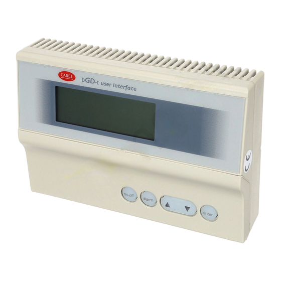
- Page 6 The display normally shows ambient temperature and humidity together with time and date if clock option is present. The pCO keypad is equipped with 15 buttons which, together with 4X20 LCD, represent the interface between user and controller. prog...
- Page 7 If, for example, the last procedure has been the setting of the printer parameters, for some seconds the last selected mask will remain on display and the LED next to the printer button will remain ON: Once the selected time has elapsed, the LED next to the printer button will be turned OFF, the one next to the menu button will be turned ON and the temperature and humidity values will be displayed.
- Page 8 PRINTER BUTTON Allows the user to manage the printer and to select its required parameters. Procedure to be followed: - press the Printer button once. Result of procedure: - the display will show a mask for the immediate setting of printing by simply pressing Enter.
- Page 9 Procedure to be followed: - press the buttons. Result of procedure: - repetition of the masks for the management of time, for the setting of the password to gain access to the time zones branch, and again for the setting of the date. Procedure to be followed: - press the Enter button when the display shows the Password selecting mask.
- Page 10 Result of procedure: - visualisation of a series of masks for the setting of all values necessary to humidity and temperature control and for the setting of set-points and differentials of connected devices. ? INFO BUTTON info Allows visualisation of the software version. Procedure to be followed: - press the Info button once.
- Page 11 Result of procedure: -the LED indicator under the ON/OFF button turns ON : Unit ON; -the LED indicator under the ON/OFF button turns OFF : Unit OFF. ALARM BUTTON Allows silencing of the buzzer which has been activated in case of alarm and resetting of alarms as soon as the reasons that caused them disappeared.
- Page 12 0,0 and at the same time the modified value will be memorised. - pCO TERMINAL BOARD REAR PART The terminal board is composed of # a section including the microprocessor # a section which allows interfacing with pCO and a serial printer CONNECTION TO pCO CONNECTION CONTROLLER...
- Page 13 The pCO controller allows voltage digital inputs to be connected with terminals ID11 - ID11R and ID12 - ID12R as shown in the picture below. When the general alarm input is open, the high pressure alarm on pCO input will be detected.
-
Page 14: Hardware: User Interface
The user interface comprises all those components, such as keypad, display and LED indicators, which are necessary for the exchange of information between the user who needs air conditioning and the microprocessor devised by CAREL for the managing of this operation. - Page 15 VG0 - Y0 COLD WATER VALVE VG0 - Y1 HOT WATER VALVE - pCO OPTIONAL BOARDS INSTALLATION Clock board This board allows to display date and time as well as the management of Time-bands. To use this board connect it to the connector (3) shown in the picture on page 3.
- Page 16 In this case it is advisable to recover the default values established by Carel and afterwards to change the ones tha are not in a accordance with the equipment.
-
Page 17: Configuration Guide
It is used during the preliminary operations, and whenever it is impossible to have access to the branch MASTER password (because the memory has been "spoiled"). - MASTER password: the value of this password is selected in the password set mask. - Page 18 2.2 STEP For each step it is possible to select the following: - the set-point of the step itself (% value of the regulation differential) - the hysteresis, that is half of the step dimension and a % value of the differential Each step is connected to a device: Cold step ------->...
- Page 19 2.3 DEFAULT VALUES The factory-set configuration provides for the following devices: - ambient temperature probe - ambient relative humidity probe - outside air temperature probe - water temperature probe - cold water valve - hot water valve - all heaters enabled (n.2) - both compressors enabled - external humidifier Here is the list of the default values the controller accepts as machine parameters...
- Page 20 In order to enable the manual functioning of the unit it is necessary to follow the procedures described in the paragraph dedicated to pCO keypad. Manual functioning of the unit is identified by the “M” letter that appears in the last...
- Page 21 2.5 TEMPERATURE CONTROL DIAGRAMS TWO-COMPRESSOR UNIT WITHOUT ENERGY SAVING OPTION COLD WATER VALVE DIFFERENTIAL (HALF OF THE TOTAL) Default values: - Set-point compressor 1: 25% Hysteresis compressor 1: 25% - Set-point compressor 2: 75% Hysteresis compressor 2: 25% In case of use of default partialised compressors, the compressor steps coincide with the relative partialisations.
- Page 22 -MANAGEMENT OF COMPRESSORS After the compressor has been turned ON, it must go on working for at least 1 min (default) (VALUE SELECTABLE THROUGH DEDICATED MASK). After the compressor has been turned OFF, it is necessary to wait for at least 6 min (default) before restarting it (VALUE SELECTABLE THROUGH DEDICATED MASK).
- Page 23 1 COMPRESSOR UNIT WITHOUT ENERGY SAVING OPTION COLD WATER VALVE DIFFERENTIAL (HALF OF THE TOTAL) Default values: - Set-point compressor: 50% Hysteresis compressor: 50% In case of use of default partialised compressors, the compressor step coincides with the relative partialisation. 1 COMPRESSOR UNIT WITH ENERGY SAVING OPTION COLD WATER VALVE DIFFERENTIAL (HALF OF THE TOTAL)
- Page 24 TWO-HEATER UNIT HOT WATER VALVE DIFFERENTIAL (HALF OF THE TOTAL) Default values: - Set-point heater 1: 25% Hysteresis heater 1: 25% - Set-point heater 2: 75% Hysteresis heater 2: 25% ONE-HEATER UNIT HOT WATER VALVE DIFFERENTIAL (HALF OF THE TOTAL) Default values: - Set-point heater: 50% Hysteresis heater: 50%...
- Page 25 - STANDARD during insertion: HEATER 1 HEATER 1 + HEATER 2 during disinsertion: HEATER 1 + HEATER 2 HEATER 1 - BINARY during insertion: HEATER 1 HEATER 2 HEATER 2 + HEATER 1 during disinsertion: HEATER 2 + HEATER 1 HEATER 2 HEATER 1 The LOW-LIMIT step intervenes during dehumidification as follows:...
-
Page 26: User Guide
(half of the total) 3. USER GUIDE The Liquid Crystal Display is the main communicative channel between pCO and user. All information that can be read on display is stored in a series of masks. All masks will be listed below. - Page 27 3.2 ALARM MASKS Each alarm condition is signalled ; - by the incorporated buzzer; - by the red LED indicator on the front panel of user interface and by the “AL” message which appears on the higher right corner of display. It is possible to display an alarm message indicating the type of problem occurred by pressing the ALARM button .
- Page 28 ¦ >ABNORMAL WORKING< ¦ +--------------------+ CONTA1 (MAINTENANCE BRANCH) +--------------------+ First mask of the maintenance branch you reach ¦Time Counter AL¦ by pressing the “Maintenance” button. This is the mask ¦Fan 00000 ¦ for the visualisation of fan/2 compressors working ¦Compressor 1 00000 ¦...
- Page 29 PRINT2 (PRINTER BRANCH) +--------------------+ Mask for the cyclic print setting. ¦ PRINTER AL¦ If the cyclic print has been selected, within the ¦ ¦ loop the following mask will be selected too. ¦Cyclic Print ¦ ¦Enabled? No¦ +--------------------+ PRINT3 (PRINTER BRANCH) +--------------------+ Mask for cyclic print interval setting ¦...
- Page 30 PASSFAS (CLOCK/TIME BANDS BRANCH) +--------------------+ Mask for the setting of the user password that ¦ DAILY TIME ZONE AL¦ allows access also to time zones masks if the ¦Insert the Password ¦ password has been correctly selected. Otherwise, ¦for Daily Time Zone:¦ the time zones masks will not be enabled.
- Page 31 ¦-- Humidity AL¦ third humidity Time Zone. ¦Daily Time Zone 3 ¦ ¦End Time 00:00 ¦ ¦Set-point : 000.0 U%¦ +--------------------+ UMIDFAS4 (CLOCK/TIME BANDS BRANCH) +--------------------+ Mask for the setting of time and set-point of the ¦-- Humidity AL¦ fourth humidity Time Zone. ¦Daily Time Zone 4 ¦...
- Page 32 +--------------------+ Setting of Energy Saving set-point/differential. ¦-- Temperature AL¦ ¦Energy Saving ¦ ¦Set-point :00.0 _C¦ ¦Differential:00.0 _C¦ +--------------------+ (USER BRANCH) +--------------------+ Setting of High/Low water temperature alarm ¦Water Temperature AL¦ thresholds. ¦Alarm Threshold ¦ ¦High Temp.: 00.0 _C¦ ¦Low Temp. : 00.0 _C¦...
- Page 33 ¦- 3-Point Valves AL¦ cooling 3-point valve, if it has been selected. ¦Cooling 3-P Valve ¦ ¦Start U%¦ ¦End U%¦ +--------------------+ RAMPE43 (USER BRANCH) +--------------------+ Setting of the values of activation/deactivation of ¦- 3-Point Valves AL¦ heating 3-point valve, if it has been selected. ¦Heating 3-P Valve ¦...
- Page 34 ¦Partialis. 1 (ES) ¦ compressor has been selected and the Energy Saving ¦Position : 000 U% ¦ option has been adopted. ¦Hysteresis : 000 U% ¦ +--------------------+ PARZ1ED_2 (USER BRANCH) +--------------------+ Setting of the values of activation/deactivation of ¦- Partialisations AL¦ the first compressor partialisation if two ¦Partialis.
- Page 35 ¦of Compressors ¦ ¦Enabled? No¦ +--------------------+ (USER BRANCH) +--------------------+ Mask for the setting of any use of one or two ¦-- Compressors AL¦ compressors (if selected) for dehumidification. ¦For Dehumidification¦ ¦Compressor 1 N.E. ¦ ¦Compressor 2 N.E. ¦ +--------------------+ DEUMID (USER BRANCH) +--------------------+ This mask will be displayed only if you have...
- Page 36 ¦Open ¦ ¦Close ¦ +--------------------+ COSTPASS (MANUFACTURER BRANCH) +--------------------+ This is the first mask of the manufacturer branch ¦-MANUFACT. BRANCH AL¦ you reach by pressing the "Menu" button and the ¦Insert the ¦ "Prog." button together. If the password has been ¦Manufacturer ¦...
- Page 37 ¦To Be Inserted: ¦ heaters or no heaters. ¦ ¦ +--------------------+ RAMPAFRE (MANUFACTURER BRANCH) +--------------------+ Activation of the cooling valve. ¦-Modulable Valves AL¦ ¦ ¦ ¦Cooling Valve ¦ ¦Enabled? No¦ +--------------------+ RAMPAFES (MANUFACTURER BRANCH) +--------------------+ This mask is selected if the cooling valve in the ¦-- Cooling Valve AL¦...
- Page 38 ¦ ¦ +--------------------+ INSCONF (MANUFACTURER BRANCH) +--------------------+ Mask for clearing and for Default values setting in ¦- Special Proced. AL¦ Back-up memory. ¦ ¦ ¦Configuration ¦ ¦Installing? No¦ +--------------------+ RITACCEN (MANUFACTURER BRANCH) +--------------------+ In this mask you can select the delay for the first ¦- Special Proced.
- Page 39 (ALARM BRANCH) +--------------------+ +--------------------+ +--------------------+ ¦ ¦ ¦ ¦ ¦ ¦ ¦ General Alarm ¦ ¦ General Alarm ¦ ¦ Pressostat ¦ ¦ Compressor ¦ ¦ Compressor ¦ ¦ Low Pressure 1 ¦ ¦ ¦ ¦ ¦ ¦ ¦ +--------------------+ +--------------------+ +--------------------+ High pressure/Overload...
- Page 40 +--------------------+ +--------------------+ ¦ -Probe Alarm- ¦ ¦ -Probe Alarm- ¦ ¦ Outlet Air ¦ ¦ Outlet Water ¦ ¦ Temperature Probe ¦ ¦ Temperature Probe ¦ ¦ Faulty/Disconnected¦ ¦ Faulty/Disconnected¦ +--------------------+ +--------------------+ AL43 WARNING AL43A +--------------------+ In the AL43 mask you can see +--------------------+ ¦...
-
Page 41: Components And Codes
PCOB000B00 fixed screw connectors - connetting cable interface/main board : cod. S90CONN002 0,8m cod. S90CONN000 1,5m cod. S90CONN001 - probes : of different type and code according to requirements. Carel reserves the right to modify its products without prior notice. - Page 42 Note: ________________________________________________________________________________________________ _______________________________________________________________________________________________________ _______________________________________________________________________________________________________ _______________________________________________________________________________________________________ _______________________________________________________________________________________________________ _______________________________________________________________________________________________________ _______________________________________________________________________________________________________ _______________________________________________________________________________________________________ _______________________________________________________________________________________________________ _______________________________________________________________________________________________________ _______________________________________________________________________________________________________ _______________________________________________________________________________________________________ _______________________________________________________________________________________________________ _______________________________________________________________________________________________________ _______________________________________________________________________________________________________ _______________________________________________________________________________________________________ _______________________________________________________________________________________________________ _______________________________________________________________________________________________________ _______________________________________________________________________________________________________ _______________________________________________________________________________________________________ _______________________________________________________________________________________________________ _______________________________________________________________________________________________________ _______________________________________________________________________________________________________ _______________________________________________________________________________________________________ _______________________________________________________________________________________________________ _______________________________________________________________________________________________________ _______________________________________________________________________________________________________ _______________________________________________________________________________________________________ _______________________________________________________________________________________________________ _______________________________________________________________________________________________________ _______________________________________________________________________________________________________ _______________________________________________________________________________________________________...
Need help?
Do you have a question about the pCO and is the answer not in the manual?
Questions and answers