Table of Contents
Advertisement
Advertisement
Table of Contents

Related Manuals for Avery Weigh-Tronix WI-125 SST


Summary of Contents for Avery Weigh-Tronix WI-125 SST
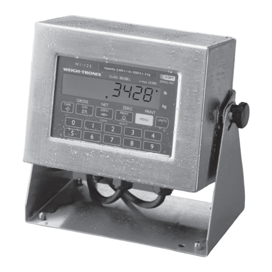
- Page 1 LED version ^ LCD version > WI-125 SST Indicator Service Manual...
- Page 2 WI-125 SST Indicator Service Manual...
-
Page 3: Table Of Contents
Indicator Diagnostics ................... 30 Test Mode ....................30 Disassembly and Reassembly ................32 Appendix 1: Earlier Versions of WI-125 ............... 35 WI-125SST LCD Version Technical Illustrations ..........37 WI-125 LED Version Technical Illustrations ............47 WI-125 SST Indicator Service Manual... -
Page 4: Specifications
VIBRATION COMPENSATION Analog Low Pass Filter: Two section with .10 second time constant for low power analog and .06 second time constant for standard analog. Software Low Pass Filter: One section with .05 second time constant. WI-125 SST Indicator Service Manual... -
Page 5: Introduction
“sealed” or “unsealed” menu. If you change the state of the switch then, it WILL before allowing you into the NOT take affect until you exit the configuration menu. Figure 1 configuration menu. WI-125 SST Indicator Service Manual... -
Page 6: Keyboard
Sends a print command and is used to select menu items. Used to access menus and move among choices in a menu. Changes the unit of measure during operations mode. Inserts a decimal point (.) when keying in values. WI-125 SST Indicator Service Manual... -
Page 7: Error Messages
Then enter a new code inside the rear panel. number—twice, as the display prompts. Now you have complete access to the configuration menu. WI-125 SST Indicator Service Manual... -
Page 8: Configuration Menu
Figure 2 Configuration Menu WI-125 SST Indicator Service Manual... - Page 9 WI-125 SST Indicator Service Manual...
- Page 10 Net - If an AZT range is set, NET will appear in the menu. This option lets you choose to enable AZT during net weighing opera- tions (ON) or disable it (OFF). The gross weight must be zero for AZT to work in net mode. WI-125 SST Indicator Service Manual...
- Page 11 “ingredient cutoffs” by keying in a number. If you pick 0, INGRED. will not appear in the menu and the cutoffs you have will be “setpoint cutoffs.” Cutoffs occur according to weight. The lightest cutoffs occur first, WI-125 SST Indicator Service Manual...
- Page 12 Backlight may be enabled or disabled in User menu. (See User's Manual) Setup, Scale, Options, Security- Code No. This option lets you change the configuration access code number to a personalized security code number. WI-125 SST Indicator Service Manual...
- Page 13 Broad. stands for broadcast. If you enable (ON) broadcast, weight data is transmitted at the display rate. Choosing OFF disables the broadcast. If broadcast is enabled, the Button, Enquire, and Auto selections are overridden and will not function. WI-125 SST Indicator Service Manual...
-
Page 14: Layout (Printing)
Combinations of these errors • Status (see note at left) is available only if Broadcast or Other is can also occur. (e.g., “3” = enabled under Enquire/Device. Range error (2) plus Motion (1)) • ID WI-125 SST Indicator Service Manual... - Page 15 Custom digits (ASCII string) COUNT Number of accumulations performed TOTAL Total accummulated weight STATUS Current scale status (stable, motion, etc.) STEADY If stable=prints<sp>. If motion=prints 'M' Prints ID if ID is enabled DELETE Deletes a layout item WI-125 SST Indicator Service Manual...
- Page 16 Sample 1 Orion 1 Label Sample 2 Orion 2 Label Sample 3 Orion 3 Label Sample 4 Barcode Label WI-125 SST Indicator Service Manual...
- Page 17 WI-125 indicator. See the User's Manual for information on the ACCUM function. Sample 5 Orion 1 "Total" Label Sample 6 Orion 2 "Total" Label Sample 7 Orion 3 "Total" Label Sample 8 Barcode "Total" Label WI-125 SST Indicator Service Manual...
- Page 18 Default Printout As Configured on a New Indicator Figure 4 Possible Print Configuration Remember, press SELECT to move up or down a level in the menu structure, and press MENU to move left or right. Figure 5 Layout Menu for Figure 4 WI-125 SST Indicator Service Manual...
-
Page 19: Customizing The Layout Menu
To delete a layout print command: With the layout print command you wish to delete on the display, press CLEAR. Find complete instructions for these procedures in the section Examples and Step by Step Instructions. WI-125 SST Indicator Service Manual... - Page 20 Sets next line's characters to double wide #78- Table 1 ASCII Control Characters under the Print Command, 1 ASCII Figure 7 Layout Submenu, 2 GROSS 4 TARE Figure 7 represents alternate choices of preformatted data. WI-125 SST Indicator Service Manual...
-
Page 21: Examples And Step By Step Instructions
(1 31), press CLEAR and +/- repeatedly until END is displayed. When END is displayed press SELECT ..1 ASCII is displayed. All the control characters under it are now gone. WI-125 SST Indicator Service Manual... - Page 22 Repeat this step until you have entered all the ASCII control code numbers you want or the indicator tells you the memory is full, then press SELECT. . . 1 ASCII is displayed in this ex- ample. WI-125 SST Indicator Service Manual...
- Page 23 Plus Use this to enable or disable a plus sign (+) before a positive weight value in printouts. Choose ON to enable the plus sign. Choose OFF (default) to preceed a weight with a space. WI-125 SST Indicator Service Manual...
-
Page 24: Table Of Ascii Control Codes
Table 2 ASCII Control Codes NOTE: Refer to your printer or computer's User's Manual for special control codes that your printer or computer responds to. WI-125 SST Indicator Service Manual... - Page 25 When ZERO, FULL, or END are displayed, the analog output follows the value selected under OUTPUT and UNITS. The only time the value is not output is while actually adjusting zero or full. WI-125 SST Indicator Service Manual...
-
Page 26: Calibration Procedures
Below are specific instructions for setting these parameters. Calibration Procedures To calibrate your WI-125 SST, you must enter the Configuration Menu outlined below. If you are already in the Configuration Menu, go directly to the procedures for setting Zero & Span and Linearity and viewing Display which are continued on the next page. -
Page 27: Setting Zero And Span
10. Press SELECT to see the displayed weight without exiting Use this mode to do a build-up the configuration menu. You may exit to normal Weighing test or to check linearity. Mode by pressing G/N. WI-125 SST Indicator Service Manual... -
Page 28: Reset Menu And Master Clear
If SETUP, ADJUST, or DATA are set to defaults, they will not appear in the information menu. If SETUP, ADJUST, or DATA appear, you have the option to reset one, two, or all three of them to default values. WI-125 SST Indicator Service Manual... -
Page 29: Reset Menu
G/N. If nothing is corrupted (no choices are flashing) you can return to weighing mode by pressing SELECT while END (after RESET) is displayed. Instructions for moving around within the Configuration Menu WI-125 SST Indicator Service Manual... -
Page 30: Indicator Diagnostics
G/N to return to normal weigh mode and begin again. 2. Move to the right through the menu selections by pressing MENU briefly. Move to the left through the menu selections by pressing MENU for 1.5 seconds or hold down for continuous scrolling. WI-125 SST Indicator Service Manual... - Page 31 REAdY to be displayed. Pressing the MENU key puts no LOOP on the display. With pins XMITT to RECV connected, LOOP is displayed. With them disconnected, no LOOP is displayed. Press SELECT to return to SErIAL. WI-125 SST Indicator Service Manual...
-
Page 32: Disassembly And Reassembly
1. Remove the tilt knobs as shown in Figure 8. Be sure the unit is unplugged before attempting any repair. Figure 8 Removing the tilt knobs 2. Remove the screws holding the base to the indicator case. See Figure Figure 9 Removing stand screws WI-125 SST Indicator Service Manual... - Page 33 Remove this board by removing the screws pointed out in Figure 12 and lifting it off the display board underneath. Outlined in white is the optional time and date card. Pull this card up from the main board once the screw holding it down is removed. WI-125 SST Indicator Service Manual...
- Page 34 Figure 13 is the RS-232 terminal block. The one on the right is the power supply board. Remove these by removing the screws pointed out by the arrows. Figure 13 RS-232 terminal and power supply board. 8. Reassemble the unit by reversing the disassembly procedure. WI-125 SST Indicator Service Manual...
-
Page 35: Appendix 1: Earlier Versions Of Wi-125
The enhanced WI-125 LCD configuration includes the choice to enable single channel accumulation and transaction count. Below is a chart referencing the model/part numbers for the old and new board/EPROM: Old P/N New P/N Description board & software board & software WI-125 SST 29400-0179 53042-1056 WI-125 SST Indicator Service Manual... - Page 36 WI-125 SST Indicator Service Manual...
-
Page 37: Wi-125Sst Lcd Version Technical Illustrations
WI-125SST INDICATOR (LCD VERSION) (115/230VAC & 12VDC) PARTS and ASSEMBLY ITEM DESCRIPTION W-T P/N Enclosure (AC, hole pattern for wt sens strain relief) 48721-0015 Encl. (AC, hole pattern for wt. sens. connector) 48721-0023 Encl. (DC, hole pattern for wt. sens. strain relief) 48721-0031 Bezel Gasket (also ref. - Page 38 The enhanced WI-125 LCD configuration includes the choice to enable single channel accumulation and transaction count. Below is a chart referencing the model/part numbers for the old and new board EPROM. Old P/N New P/N Description Board & Software Board & Software WI-125 SST 29400-0179 53042-1056...
- Page 39 WI-125SST INDICATOR (LCD VERSION) (115/230VAC) W/O WEIGHT SENSOR CONNECTOR PC BOARD/CABLE IDENTIFICATION...
- Page 40 WI-125SST INDICATOR (LCD VERSION) (115/230VAC) W/O WEIGHT SENSOR CONNECTOR EXTERNAL INTERFACE CONNECTIONS NOTE: On systems using remote sense (7 wires), store jumper on a single pin of P7 & P8. On systems not using remote sense (5 wires), jumper P7-1 to P7-2 and P8-1 to P8-2 with jumper. Weight Sensor Interface Connections Terminal Board Signal...
- Page 41 WI-125SST INDICATOR (LCD VERSION) (115/230VAC) W/ WEIGHT SENSOR CONNECTOR PC BOARD/CABLE IDENTIFICATION...
- Page 42 (LCD VERSION) (115/230VAC) W/ WEIGHT SENSOR CONNECTOR EXTERNAL INTERFACE CONNECTIONS RS-232 Interface Connections Terminal Board Signal TB1-1 Signal Ground TB1-2 Transmit Data TB1-3 Receive Data TB1-4 Data Terminal Ready TB1-5 Clear To Send TB1-6 Chassis Ground TB1-7 +12 VDC TB1-8 Power Return...
- Page 43 WI-125SST INDICATOR (LCD VERSION) (115/230VAC) W/ WEIGHT SENSOR CONNECTOR PC BOARD/CABLE CONNECTIONS...
- Page 44 WI-125SST INDICATOR (LCD VERSION) (12VDC) W/O WEIGHT SENSOR CONNECTOR EXTERNAL INTERFACE CONNECTIONS NOTE: On systems using remote sense (7 wires), store jumper on a single pin of P7 & P8. On systems not using remote sense (5 wires), jumper P7-1 to P7-2 and P8-1 to P8-2 with jumper. Weight Sensor Interface Connections Terminal Board Signal...
- Page 45 WI-125SST INDICATOR (LCD VERSION) (115/230VAC & 12VDC) MAIN BOARD & POWER SUPPLY BOARDS BP-25R BATTERY/CHARGER DIMENSIONAL OUTLINE BP-25R EXTERNAL BATTERY w/ BUILT-IN CHARGER, incl. CABLE (OPTIONAL) P/N 46839-0018mts (115VAC) ,-0026mts (230VAC) CAUTION ! Failure to observe proper polarity when replacing battery (B1) may cause an explosion.
- Page 46 WI-125SST INDICATOR (LCD VERSION) (115/230VAC & 12VDC) KEYPAD & SCHEMATIC, SERIAL / WEIGHT SENSOR BOARDS, NOTE: TIME & DATE BOARD (OPTIONAL) On systems using remote sense (7 wires), store jumper on a single pin of P7 & P8. On systems not using remote sense (5 wires), jumper P7-1 to P7-2 and P8-1 to P8-2 with jumper.
-
Page 47: Wi-125 Led Version Technical Illustrations
WI-125SST INDICATOR (LED VERSION) (115/230VAC) PARTS AND ASSEMBLY ITEM DESCRIPTION W-T P/N Enclosure 52263-0011 Front Bezel Gasket (also ref. keypad kit) 48723-0013 Keypad Kit (incl: keypad, backer & gasket) (USA) 60265-0038 Keypad Kit (incl: keypad, backer & gasket) (EURO) 60265-0046 Standoff, #6 x 5/8”L, F-F, (used w/ time &... - Page 48 WI-125SST INDICATOR LED VERSION) (115/230VAC) SYSTEM BLOCK DIAGRAM...
- Page 49 WI-125SST INDICATOR (LED VERSION) MAIN BOARD ASSY IDENTIFICATION P/N 52091-0019 (115VAC (w/o E-Prom) RS-232 Interface Connections 52091-0035 (230VAC) (w/o E-Prom) Terminal Board Signal TB8-1 Signal Ground Weight Sensor Interface Connections TB8-2 Transmit Data Terminal Board Signal W-T Wire Color TB8-3 Receive Data TB8-4 Data Terminal Ready...
- Page 50 WI-125SST INDICATOR LED VERSION) (115/230VAC) KEYPAD, OPTIONAL P.C. BOARDS...
- Page 51 Declaration of Conformance to SMA Standard Year of Declaration 2002 Production Meets Type ® * We the manufacturer of Model Type Certificate and Number Issued by WI-125 Electronic Indicator NTEP CC 92-167A4 NCWM Declare in our responsibility the conformance of the above listed models and types to the mentioned certificates and the requirements of the SMA standard.
- Page 52 Pointe Claire, QC H9R 4R7 Canada ® Weigh Bar is a registered trademark Telephone: 514-695-0380 of Avery Weigh-Tronix and may be registered in certain jurisdictions. Toll free: 800-561-9461 All brands and product names used Facsimile: 514-695-6820 within this document are trademarks www.weigh-tronix.ca...
Need help?
Do you have a question about the WI-125 SST and is the answer not in the manual?
Questions and answers