
Summary of Contents for Framo Morat COMPACTA MS12
- Page 1 Mounting instructions Slip-on geared motors COMPACTA MR6, MS12, MR30, AG160 MS 12 AG 160 MR 30 MR 6 Please read the mounting instructions prior to any work!
- Page 2 Creation 05/09/2013 3.6 / 7.1 Rephrased F. Milkau 20/03/2014 All types together F. Milkau Revision 2014-03-20 © Framo Morat GmbH Franz-Morat-Strasse 6 D – 79871 Eisenbach Phone: +49 (0)7657 - 880 Fax: +49 (0)7657 - 88333 E-Mail: info@framo-morat.de Internet: www.framo-morat.de...
-
Page 3: Table Of Contents
Table of contents 1 Table of contents Table of contents ..............3 General ..................5 Mounting instructions ..............5 Symbols, abbreviations, terminology .......... 5 Explanation of symbols ............... 6 Limitation of liability ..............7 Customer service ................ 8 Copyright protection ..............8 Safety .................. - Page 4 Table of contents Setting MR 6 ................22 Setting 22 Setting MS12, MR 30, AG 160 ..........24 Commissioning .................26 Overview of the switching ranges ..........26 Operation ................27 10 Maintenance ................27 11 Failures ..................27 11.1 What to do in case of failures ...........27 11.2 Failures table ................27 12 Annex..................28 13 Index ..................28...
-
Page 5: General
General 2 General Mounting instructions The mounting instructions provide all necessary information for safe and efficient handling and mounting of the motor. It is an integral part of the motor and must be kept at hand, in order to be accessible at any time for the operating staff. -
Page 6: Explanation Of Symbols
General Explanation of symbols Warnings and safety instructions The warning and safety instructions in this manual are indicated with pictograms and highlighted with a grey background. In addition, warning and safety instructions that indicate fundamental hazards begin with signal words indicating the extent of the damages. -
Page 7: Limitation Of Liability
General Hints and recommendations NOTICE! ...highlights hints and recommendations for efficient and trouble-free operation. Particular safety instructions The following pictograms are used together with safety instructions to indicate particular hazards: ... hazards due to hot surfaces. Risk of burns and skin injuries due to heat in case of non compliance with the safety instructions. -
Page 8: Customer Service
General Warranty The manufacturer guarantees the correct functioning of the process technology used and the performance parameters identified. The guarantee period begins at the fault-free handover. During the guarantee period, the cover of the terminal box or of the limit switch systems may be opened only for connecting the motor. Any further disassembly releases the manufacturer of any guarantee obligation. -
Page 9: Safety
Safety 3 Safety This section presents all safety aspects for the protection of the user and of the operator against any possible hazard and for the safe and trouble-free operation of the equipment. Significant risks may appear in case of non-compliance with the stated mounting instructions, warnings and safety instructions. -
Page 10: Responsibility Of The Operator
Safety Responsibility of the operator Operator The operator is any natural or legal person using the motor or making it accessible to third parties for use, and who is responsible during the use for the safety of the user, of the personnel or of the third parties. -
Page 11: Responsibility Of The Personnel
Safety Responsibility of the personnel The slip-on geared motor COMPACTA is used for industrial purposes. Therefore, the personnel are subject to the legal obligations concerning occupational safety. In addition to the warnings and safety instructions of this manual, the safety, accident prevention and environmental protection provisions applicable to the field of operation of the appliance must be adhered to. -
Page 12: Personal Protection Equipment
Safety Specialised personnel Specialised personnel means persons who, due to their professional training, knowledge and experience, and to their knowledge of the applicable provisions, are able to carry out correctly the work they are entrusted with, to recognise possible risks on their own and to avoid injury to persons or damage to property. -
Page 13: Risks Due To Thermal Hazards
Safety 3.7.1 Risks due to thermal hazards Hot surfaces CAUTION! Risk of burns due to hot surfaces! Contact with hot components may cause burns. – Before starting any work, make sure that the motor cooled down/heated up to ambient temperature. Spare parts WARNING! Risk of injury due to wrong spare parts! -
Page 14: Labelling
Safety 3.10 Labelling The following symbols and information labels are placed on the motor to indicate possible risks. WARNING! Risk of injury due to illegible labels! Illegible labels lead to unrecognisable risk sources and may lead to hazardous situations for persons or lead to damages to property. -
Page 15: Technical Specifications
Technical specifications 4 Technical specifications Please also refer to the separated specific data sheet in addition to the technical specifications Operating conditions Item Value Unit Temperature range 0 to + 60 °C Relative air humidity 0 to 60 Without condensation Avoid direct moisture, dust accumulation and frost. -
Page 16: Equipment Identification
Framo Morat GmbH and the customer delivers them at the Framo Morat GmbH premises. If the national laws in force require other services, we adapt our services in compliance with these provisions. -
Page 17: Components Overview
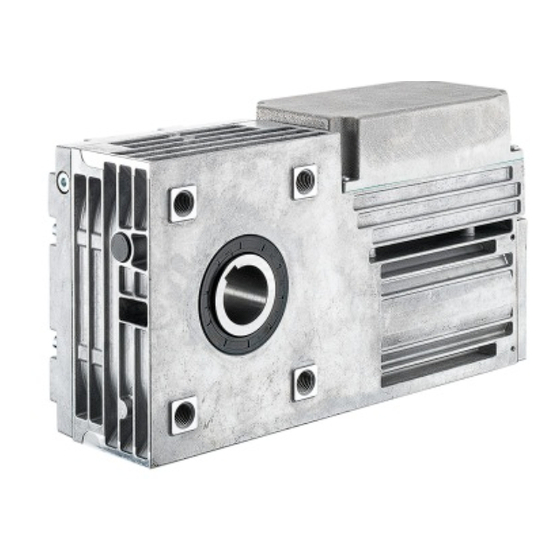
Components overview AG 160 MR 30 MS 12 Motor Ref. Description Motor Limit switch system Reduction gear MS12 Motor Limit switch system Reduction gear MR 6 MR30 Motor Limit switch system Reduction gear AG160 Motor Limit switch system Reduction gear... -
Page 18: Transportation
Transportation 6 Transportation CAUTION! Risk of injury! Risk of injury due to a transported item falling down. Wear safety shoes during transportation. Transportation inspection Upon receipt of the delivery, check immediately the condition of the received items for completeness and damages. In the event of externally recognizable transportation damages: ►... -
Page 19: Mounting
Mounting 7 Mounting The motor may be mounted exclusively by specialised electricians. WARNING! Risk of injury for unauthorised persons! Non-trained persons do not know the risks in the working area and are considered as unauthorised persons. – Keep unauthorised persons away fro the working area, in case of doubt approach these persons and instruct them to leave the working area. - Page 20 Mounting BEWARE! Respect the correct screw length, since a wrong length would damage the housing. Min. screwing Max. screwing Type Torque depth depth 14 NM 10 mm 15 mm MS12 14 NM 10 mm 12 mm MR30 25 NM 12 mm 15 mm 25 NM 12 mm...
-
Page 21: Electrical Commissioning
Mounting Electrical commissioning NOTICE! Use the attached electrical diagram to carry out the electrical connections. NOTICE! When carrying out the electrical connection, make sure to use the right operating voltage (see the nameplate). Connect all external control and power cables to the corresponding internal contacts, as shown on the electrical diagram. -
Page 22: Setting
Setting 8 Setting Setting MR 6 Limit switch coupling pin for direction of rotation 1, engaged Limit switch coupling pin for direction of rotation 2, disengaged Direction of rotation 1 Direction of rotation 2 Limit switch Outside switches from inside towards outside Inside Setting... - Page 23 Setting BEWARE! Risk of damages to the motor. – Comply with the maximum limit witch range stated in the data sheet "Technical Data". Proceed as follows for commissioning: 1. Move the motor to a limit position. 2. Press the coupling pin corresponding to the direction of rotation down.
-
Page 24: Setting Ms12, Mr 30, Ag 160
Setting Setting MS12, MR 30, AG 160 Risk of electric shock – Work only at de-energized workplaces. – Protect the workplace against unintentional switching- on of the power supply. – Only connect the motor to a network equipped with operating circuit breakers. –... - Page 25 Setting MR 30: AG 160: Direction of rotation information MS 12 Direction of rotation information MR 30 Direction of rotation information AG 160...
-
Page 26: Commissioning
Setting Commissioning WARNING! Risk of injury in case of insufficient qualification! Improper working may lead to injury to persons and damages to materials. – Whatever activity may only be performed by persons having the required training, the necessary knowledge and the experience. There is no general procedure for commissioning all three motors. -
Page 27: Operation
No specific operation is required for the COMPACTA slip-on geared motors MS12, MR30 and AG 160, since they have been designed for integration in plants. 10 Maintenance The slip-on geared motors COMPACTA MS12, M30 and AG160 are factory-provided with lifetime lubrication and are maintenance- free. 11 Failures 11.1 What to do in case of failures... -
Page 28: Annex
Annex 12 Annex ► Electrical diagram ► Declaration of integration 13 Index Operation..............29 Abbreviations ............... 5 Operator ..............11 Accident ..............15 Packaging ..............21 Construction and function.......... 19 Personal protection equipment ........ 14 Copyright protection ............ 9 Personnel Customer service ............
Need help?
Do you have a question about the COMPACTA MS12 and is the answer not in the manual?
Questions and answers