Table of Contents
Advertisement
Quick Links
Advertisement
Chapters
Table of Contents

Related Manuals for Beha-Amprobe GT-800


Summary of Contents for Beha-Amprobe GT-800
- Page 1 GT-600/GT-800 Portable Appliance Tester Users Manual...
- Page 2 GT-600/GT-800 Instruction Manual...
-
Page 3: Instruction Manual
GT-600/GT-800 Instruction Manual A MPROBE GT-600/GT-800 Instruction Manual 2014 FLUKE DEUTSCHLAND... -
Page 4: Table Of Contents
Description of warning marks on the front panel ..........10 Operation Elements and Connectors ..............11 Front panel of the GT-600 Tester ................11 Front panel of the GT-800 Tester ................12 Cover of the GT-600 Tester ..................13 Cover of the GT-800 Tester ..................14 Preparation of the GT-600/GT-800 Tester ............... - Page 5 Cleaning ........................58 Calibration Interval ....................58 Fuse Replacement ....................59 List of Possible Displayed Errors ................60 Reset of the GT-600/GT-800 Tester ................ 61 Pre-Tests and Protection ..................62 Technical Specifications ..................65 Technical Specifications ..................65 Variation Factor Errors ..................... 73 Limited Warranty and Liability ................
-
Page 6: Safety Information, Warning
GT-600/GT-800 Instruction Manual Safety information, Warning Measurements of the electrical safety on appliances should only be carried out by properly trained and competent persons! Carefully read the safety information before using the appliance tester GT-600/GT-800. References marked on the instrument or in this instruction manual: Warning of a potential danger, comply with instruction manual. -
Page 7: Introduction
Insulation resistance measurement (R ), test voltage 500 VDC (and 250 VDC GT-800 only). Appliances class I with heater, class I, class II and class III can be tested. Substitute leakage current measurement (I ), test voltage 45 V AC. -
Page 8: Scope Of Supply
Adjustable measurement times in single measurement mode. Three selectable languages (English, German and French) Scope of Supply 1 pc Portable Appliance Tester GT-600/GT-800 with permanently connected mains cable (Schuko) 1 pc Accessory bag (fixed to housing) 1 pc Test lead, 1.5 m, 600 V CAT III, black... -
Page 9: Safety Measures
GT-600/GT-800 Instruction Manual Safety Measures The GT-600/GT-800 appliance tester has been built and tested in compliance with the valid safety regulations and left the factory in safe and perfect condition. In order to maintain this condition and to ensure safe instrument operation, the user must pay attention to the references and warnings contained within this instruction manual. -
Page 10: Appropriate Usage
GT-600/GT-800 Instruction Manual Appropriate Usage WARNING The instrument may only be used under those conditions and for those purposes for which it was conceived. For this reason, in particular the safety references, the technical data including environmental conditions and the usage in dry environments must be followed. -
Page 11: Operation Elements And Connectors
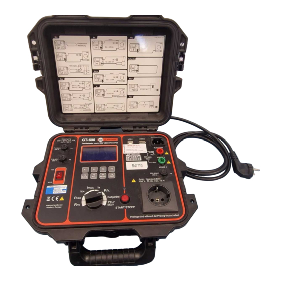
GT-600/GT-800 Instruction Manual Operation Elements and Connectors Front panel of the GT-600 Tester Figure 1: Operational elements and connectors on GT-600 Tester... -
Page 12: Front Panel Of The Gt-800 Tester
GT-600/GT-800 Instruction Manual Front panel of the GT-800 Tester Figure 2: Operational elements and connectors on GT-800 Tester 1 ..Mains input fuse F1 T16 A (H) / 250 V, 5 × 20 mm 2 ..Mains input fuse F2 T16 A (H) / 250 V, 5 × 20 mm 3 .. -
Page 13: Cover Of The Gt-600 Tester
GT-600/GT-800 Instruction Manual Cover of the GT-600 Tester, connection diagrams and limit values Figure 3: Brief instructions with limit values (GT-600) -
Page 14: Cover Of The Gt-800 Tester
GT-600/GT-800 Instruction Manual Cover of the GT-800 Tester, connection diagrams and limit values Figure 4: Brief instructions with limit values (GT-800) Measurement accessories are stored in the accessory bag on the top of the tester. -
Page 15: Preparation Of The Gt-600/Gt-800 Tester
1) Connect the GT-600/GT-800 to a correctly installed Schuko mains socket. 2) Use the mains switch “ON/OFF“ (4) to turn on the GT-600/GT-800. 3) After turning on the GT-600/GT-800, pilot lamp of the power switch (4) will switch on and the display (17) will show idle readout of selected function. -
Page 16: Limit Value Setting
GT-600/GT-800 Instruction Manual Limit value setting Limit value is offered in all functions except in P/I and CLAMP. For limit value setting press the “LIM” menu key (menu key F4) then use the menu keys “+”, “– “, “STD” (Standard) or “CALC” (Calculation). The menu key F8 “EXIT” can be used to exit limit value setting display. -
Page 17: Visual Inspection
GT-600/GT-800 Instruction Manual The tests should only be performed by competent persons who are familiar with the requirements of the type of tests suitable for portable appliances. It is potentially hazardous for both user and appliance should the wrong type of tests be undertaken or if testing is carried out in an incorrect sequence. -
Page 18: Protective Bonding Test 5 A / 0.2 A (R )
GT-600/GT-800 Instruction Manual Protective Bonding Test 5 A / 0.2 A (R The protective bonding test measures the resistance between PE terminal of test socket and PROBE 1 terminal. This test applies to class I appliances only. Remarks: To obtain correct protective bonding test results you must have compensated (zeroed) the test lead, see the section “Test lead... - Page 19 GT-600/GT-800 Instruction Manual Display explanation: Figure 8: Display in protective bonding test R 1 ..“ AUT” / “ MAN” menu key, for selection of automatic / manual start of the measurement. 2 ..“COMP” menu key, for test lead compensation.
- Page 20 GT-600/GT-800 Instruction Manual Where: ... 0.01786 mm /m (Cu specific resistance) L .. cable length in m A .. cross section in mm Specific information that can be shown on the display: Information displayed Description Test lead is not compensated (no “C” mark on...
-
Page 21: Insulation Resistance Test 250 V / 500 V (Riso )
Test probe PROBE 1 and test probe PROBE 2 (at class III). Warnings The test voltage is either 500 V (or 250 Vd.c. at GT-800 only). Do not touch the appliance during the insulation test! If the test fails, any metal part of the appliance could become live! ... - Page 22 4 ..Test result status ( ... result OK, X ... result not OK). 5 ..Selected protection class (PC I-HEATER, PC I, PC II or PC III). 6 ..Selected test voltage 500 V (or 250 V at GT-800 only). 7 ..Pre-set pass/fail limit value.
- Page 23 GT-600/GT-800 Instruction Manual Specific information that can be shown on the display Information displayed Description External voltage is applied to one or more test terminals, see the explanation in section EXTERNAL VOLTAGE “Pre-Tests and Protection”. Test lead is not connected to PROBE 2 (at PC USE PROBE 2 II appliances).
-
Page 24: Substitute Leakage Current Test (Isub )
GT-600/GT-800 Instruction Manual Substitute Leakage Current Test (I The substitute leakage current test measures the leakage current between L/N terminals of test socket and PE terminal of test socket in parallel with PROBE 2 (at class I, class II). L/N terminals are shorted by the tester for this test. - Page 25 GT-600/GT-800 Instruction Manual Display explanation: L1.00mA 1.22 Figure 15: Display in substitute leakage current test I 1 ..“PC” menu key, for selection of protection class (PC I or PC II). 2 ..“LIM” menu key, for pass/fail limit value setting.
-
Page 26: Protective Conductor Current Test (Ipe() )
PE() The protective conductor current test measures the earth leakage current in the protective conductor (PE) of appliances connected to the test/mains socket of the GT-600/GT-800. The measurement is carried out by the differential method. Warning NEVER carry out this test unless you have first carried out a thorough visual inspection followed by a test of the protective bonding resistance (for class I appliances), and then a test of insulation resistance. - Page 27 GT-600/GT-800 Instruction Manual Display explanation: Figure 17: Display in protective conductor current test I 1 ..“POL” menu key, for selection of mains voltage polarity (GT-800 only). 2 ..“LIM” menu key, for pass/fail limit value setting. 3 ..Test result status ( ... result OK, X ... result not OK).
-
Page 28: Touch Current Test (I T )
PROBE 2 and internal resistance of approx. 2 k to earth. The device under test is not necessary to be connected to the test/mains socket of the GT-600/GT-800, it can be also externally powered. The measurement is carried out by the direct method. - Page 29 Figure 19: Touch current test connections at appliance class II Display explanation: Figure 20: Display in touch current test I 1 ..“POL” menu key, for selection of mains voltage polarity (GT-800 only). 2 ..“LIM” menu key, for pass/fail limit value setting.
- Page 30 GT-600/GT-800 Instruction Manual Specific information that can be shown on the display Information displayed Description Warning! Mains voltage will be applied to MAINS SWITCH ON test/mains socket after confirming this CONTINUE? message! Note! No device is connected to test/mains socket, or mains switch on device not...
-
Page 31: Power, Load Current Test (P/I L )
GT-600/GT-800 Instruction Manual Power, Load Current Test (P/I The power/load current test measures the apparent power S, active power P mains voltage U , load current I and power factor PF of the appliance, connected to mains test/mains socket. Warning ... - Page 32 GT-600/GT-800 Instruction Manual Display explanation: Figure 22: Display in power / load current test P/I 1 ..Function selected by the rotary switch. 2 ..Main result (apparent power in VA). 3 ..Sub-results (active power P in W, mains voltage U...
-
Page 33: Clamp Current Test ( ) (Gt-800 Only)
GT-600/GT-800 Instruction Manual Clamp Current Test ( ) (GT-800 only) The test with the external clamp adapter measures the current in clamped conductor. The function is intended to measure: The protective conductor current (earth leakage current) in the protective conductor (PE). - Page 34 GT-600/GT-800 Instruction Manual Figure 25: Load current test connection Display explanation: 0 ... 20mA MAX: 2.50mA 1.05 Figure 26: Display in CLAMP current test ( 1 ..“RNG” menu key, for selection of measurement range (0...20 mA or 0...60 A).
-
Page 35: Iec Cord Test (Cord/Prcd)
Following parameters are tested and measured: Visual inspection Protective bonding resistance Insulation resistance R between PE and L/N conductors (L/N conductors are shorted by the GT-600/GT-800 Tester) L conductor continuity N conductor continuity L and N condition (OK/shorted). CORD... - Page 36 Procedure to test a mains cable extension leads or cable reels: 1) Use a standard IEC cable as a test adapter to connect tested mains extension coupling to IEC connector (14) of the GT-600/GT-800 Tester. 2) Compensate the test adapter: Connect the test adapter according to the figure 27 first and press the “COMP”...
-
Page 37: Prcd Test (Cord/Prcd) (Gt-800 Only)
GT-600/GT-800 Instruction Manual PRCD Test (CORD/PRCD) (GT-800 only) The PRCD test function of the GT-800 does a full test of PRCD 2-pole, 3-pole and type S (AC types). Following parameters are tested and measured: Visual inspection Confirm pass of visual test by the menu key “YES”. - Page 38 GT-600/GT-800 Instruction Manual Figure 30: PRCD test connection Display explanation: Figure 31: Display in PRCD test 1 ..“ ”menu key, to move the cursor down when checking test sub-results. 2 ..“ ”menu key, to move the cursor up when checking test sub- results.
- Page 39 PRCD is faulty. PRESS PRCD ON Press ON button on PRCD! PRESS PRCD TEST Press TEST button on PRCD! PRESS STOP Press STOP button on GT-800! In order to save displayed measurement results see the “Memorizing example” section.
-
Page 40: Protective Extra Low Voltage Test (Pelv)
GT-600/GT-800 Instruction Manual Protective Extra Low Voltage Test (PELV) The test measures the protective extra low voltage between any accessible conductive part of tested appliance and earth (PE). Figure 32: PELV test connection Display explanation: Figure 33: Display in PELV test 1 .. -
Page 41: Safety Extra Low Voltage Test (Selv)
GT-600/GT-800 Instruction Manual Safety Extra Low Voltage Test (SELV) The test measures the safety extra low voltage between two accessible conductive parts of tested appliance. Figure 34: SELV test connection Display explanation: Figure 35: Display in SELV test 1 ..“PELV/SELV” menu key, for selection of measurement function SELV or PELV). -
Page 42: Auto Test (Gt-800 Only)
GT-600/GT-800 Instruction Manual AUTO Test (GT-800 only) This is most common used test mode as it leads the operator through the whole test procedure. There are 13 factory-programmed Auto-Tests and free space for additional 17 customer-created ones. Factory-programmed Auto-Tests for class I appliances (GERMAN REGION) - Page 43 GT-600/GT-800 Instruction Manual Factory-programmed Auto-Tests for class I appliances (ENGLISH REGION) (listed figures present limit values in each test) Tests Visual Inspection Protective bonding 0.10 0.10 resistance 200 mA () Protective bonding resistance 5 A () Insulation resistance 500 V 1.00 1.00 1.00 1.00 1.00 1.00 1.00...
- Page 44 GT-600/GT-800 Instruction Manual Idle display explanation: Figure 36: Example of idle display in AUTO-TEST function 1 ..“ ”menu key, to move the cursor down in order to check the set of tests to be done. 2 ..“ ”menu key, to move the cursor up in order to check the set of tests to be done.
- Page 45 GT-600/GT-800 Instruction Manual AUTO-TEST modes There are two AUTO-TEST modes: STANDARD mode This mode is advised to be used when operator is starting with AUTO tests in generally in order to easily follow the AUTO test procedure step by step. Each new measurement has to be started with START button. Once the operator is familiar with AUTO tests, FAST mode is advised to be used.
-
Page 46: Menu Functions
GT-600/GT-800 Instruction Manual Menu Functions For further selections, entries and display of instrument’s settings, press the “MENU” function key (F7), the following selection menu appears. Figure 37: “Menu” display 1 ..“▼” menu key (down) to move the cursor down 2 .. -
Page 47: Memory Menu
USB2 connector as a confirmation the memory stick is recognized by the GT-600/GT-800 Tester. Note! The USB memory stick has to be FAT12, FAT16 or FAT32 formatted, sector size 512 Byte. - Page 48 GT-600/GT-800 Instruction Manual RENAME AUTO-TEST: Select the AUTO Test you wish to rename first by using the “A▼” and “A▲” menu keys then confirm the RENAME AUTO-TEST selection by pressing the “” menu key. Use the “▼”, “▲” and “” menu keys to create new name, then confirm the name by pressing the “”menu key.
-
Page 49: Setup Menu
REGION: Select the region (GERMANY or ENGLAND) where the GT-600/GT-800 will be used. Use the “▼”, “▲” and “” menu keys to select appropriate one. Factory- programmed AUTO Testes and limit values of the tests depend on selected region. See the section “AUTO Test”. -
Page 50: Language Menu
GT-600/GT-800 Instruction Manual offered later when results of selected AUTO Test will be saved by pressing the function “SAVE” key. Recognition of selected mode: Selected mode will be identifiable in “SAVE” operation through displayed “APP” (appliance) mark. Example 1: :145 145 (inversed APP presents selected... -
Page 51: Memory Features
GT-600/GT-800 Instruction Manual Memory Features When saving test results every test result must obligatory be dedicated to an Appliance (APP). Besides Client (CLI), Site (SIT), Location (LOC) and Description (DES) can optionally be assigned to saved test result. Above mentioned data (APP and optionally CLI, SIT, LOC and DES) must be entered / selected before storing measurement results. -
Page 52: General Memory Operations
GT-600/GT-800 Instruction Manual General Memory Operations Menu key “NEW” Press it to start entering new appliance name. This operation is required always after pressing the “SAVE” menu key (if the appliance is to be entered manually without using barcode reader). -
Page 53: Memorizing Example
GT-600/GT-800 Instruction Manual Memorizing Example In order to save measurement result, follow the next instructions: 1) Carry out the measurement, result is displayed. 2) Press the “SAVE” function key (5), blank level “APP” (appliance) will be marked. Barcode reader is not used: 3) Press the “NEW”... -
Page 54: Recall Data
GT-600/GT-800 Instruction Manual COMPUTER AMPROBE PURCHASING DPT GLOTTERTAL SERVICE 03/11/14 Figure 39: Example of memorizing address Recall Data In order to recall stored measurement result, follow the next instructions: 1) Press the “RCL” menu key (5), last saved result with belonging address will be offered, appliance level “APP”... -
Page 55: Entry Of Memory Address Using External Keyboard
Menu key “+“ (3) Menu key “-“ (3) Table 1: Functions of the USB keyboard (German version) Note! Use the USB keyboard listed in the “Available Accessories” section only, otherwise it may not be recognized by the GT-600/GT-800 Tester. - Page 56 Notes! Use the USB keyboard listed in the “Available Accessories” section only, otherwise it may not be recognized by the GT-600/GT-800 Tester. Only one USB input/output (USB1 or USB2) can be used simultaneously, the first recognized one will be active!
-
Page 57: Entry Of Memory Address Using Barcode Reader
Before first using the above mentioned barcode reader it is required to configure it as follows: - Connect the barcode reader to GT-600/GT-800 (or to PC) and switch on the GT- 600/GT-800 (or PC) in order to assure proper power supply. -
Page 58: Maintenance
GT-600/GT-800 Instruction Manual - Switch the GT-600/GT-800 tester off and on again after scanning above mentioned code. Maintenance When using the instrument in compliance with the instruction manual, no special maintenance is required. However, should functional errors occur during normal operation, our after sales service will repair your instrument without delay. -
Page 59: Fuse Replacement
If, due to overload or improper operation, a fuse blows, it is necessary to obey the following notes for replacement: WARNING Prior to replacement of blown fuse, the appliance tester GT-600/GT-800 must be disconnected from all measuring circuits and mains supply cord must be disconnected from mains supply. -
Page 60: List Of Possible Displayed Errors
GT-600/GT-800 Instruction Manual List of Possible Displayed Errors The following Errors can be displayed during operation the GT-600/GT-800 Tester: ERROR 1: Internal measurement path in any tests except CLAMP is interrupted, probably due to blown internal fuse. Please send the instrument to a service department in order to be serviced. -
Page 61: Reset Of The Gt-600/Gt-800 Tester
RESET function. Switch off the GT-600/GT-800 Tester by using the mains switch (4). Press and keep pressing the function key SAVE (F5) while switching on the GT- 600/GT-800 Tester by using the mains switch (4). -
Page 62: Pre-Tests And Protection
GT-600/GT-800 Instruction Manual Pre-Tests and Protection Function Tests, protections Notes Switching - Grounding of mains Pre-test. ON the plug PE terminal If the PE terminal is not sufficiently grounded, then “PE instrument DISCONNECTED! TURN OFF NOW!” message will be displayed and any further operation will be disabled. - Page 63 GT-600/GT-800 Instruction Manual 0.15 mA Path pre-test (self-test). PE() SUB INT If the instrument’s measurement path is interrupted e.g. due to blown internal fuse, then “ERROR 1” message will be displayed and further I tests will be disabled. PE() 20.00 mA Pre-test.
- Page 64 GT-600/GT-800 Instruction Manual - Fuse F2 Pre-test. If the F2 fuse is blown, then “FUSE 2!” message will be displayed and further P/I tests will be disabled. CLAMP - Internal fuse If internal fuse is blown, then “ERROR 2!” message will be displayed and further CLAMP tests will be disabled.
-
Page 65: Technical Specifications
Max. load output current 16 A Display Graphic LCD 128x64 dots with blue backlight Function selection 10-pos. (GT-800) / 8-pos. (GT-600) rotary switch Result limits Adjustable, refer to the adjustment range in each function (visual and acoustic signal in case of exceeded value) - Page 66 GT-600/GT-800 Instruction Manual Protective Bonding Resistance - 5A (R 0.10 ... 10.00 Measurement range 0.00 ... 11.00 Display range 0.01 Resolution Accuracy ± (5% rdg. + 3 digits) Operational error ± 13% Adjustable 0.01 ... 11.00 , calculation (by...
- Page 67 0.30 M (class I with heater), 1.00 M (class I), 2.00 M (class II), 0.25 M (class III) Test voltage (U 500 V DC (and 250 V DC GT-800 only), (floating output) Test voltage tolerance -0% ... +25% Test current (500 V range) >1 mA DC (at 500 k...
-
Page 68: Touch Current
GT-600/GT-800 Instruction Manual Substitute Leakage Current TRMS (I Available protection class I and II Measurement terminals class I L/N against (PE on test socket in parallel with PROBE 2) Measurement terminals class II L/N against PROBE 2 Measurement range 0.25 ... 20.00 mA Display range 0.25 ... -
Page 69: Apparent Power (Kva) 3.0
GT-600/GT-800 Instruction Manual Frequency range DC ... 100 kHz (characteristics according to DIN EN 61010-1 Annex A, fig. A.1 and VDE 0411 Part 1) Measurement method Direct Internal resistance (via probe) 2 k Max. ext. voltage at PROBE 2 250 V... - Page 70 Load Power / Current (P/I Power factor (PF) Display range 0.00 ... 1.00 Tolerance Not defined Clamp Current TRMS ( ) / Range 0...20 mA (GT-800 only) Measurement range 1.0 ... 20.0 mA Display range 0.5 ... 20.0 mA Resolution 0.1 mA Accuracy (without clamp error) +/- (5% rdg.
- Page 71 ISO-250V fixed limit value approx. 1 M). test lead compensation Yes, 0.00 ... 5.00 Cord R PRCD Test (GT-800 only) Type of PRCD AC (2-pole, 3-pole and type S) N Nominal differential current I Selectable 10 mA or 30 mA...
- Page 72 25 V and 50 V Input resistance 20 M Common mode input voltage 50 V max. Frequency range 0 ... 723 Hz AUTO Test measurements (GT-800 only) Number of factory-programmed AUTO tests (fixed) 13 Number of available customer-created AUTO tests...
-
Page 73: Variation Factor Errors
GT-600/GT-800 Instruction Manual Variation Factor Errors Variation Factor Designation (%) Variation Error Position Supply Voltage (not used) Temperature Current Consumption (not used) Magnetic Fields Impedance (not used) Capacitance Current Waveshape... -
Page 74: Limited Warranty And Liability
GT-600/GT-800 Instruction Manual Limited Warranty and Limitation of Liability It is guaranteed that this BEHA-AMPROBE product is free of material and manufacturing damages for the time period of 24 months starting from the date of purchase. This warranty does not include fuse malfunctions, as well as damages caused by accidents, negligence, misusage, unauthorised modifications, abnormal operating conditions or improper handling. - Page 75 GT-600/GT-800 Instruction Manual Subject to technical changes without notice! 11/2014 Version 1.4...
Need help?
Do you have a question about the GT-800 and is the answer not in the manual?
Questions and answers