
Related Manuals for Ansul Checkfire MP-N


Summary of Contents for Ansul Checkfire MP-N
- Page 1 002750 CHECKFIRE MP-N ELECTRIC DETECTION & ACTUATION SYSTEM Installation, Recharge, Inspection, and Maintenance Manual...
- Page 2 Note: The converted metric values in this document are provided for dimensional reference only and do not reflect an actual measurement. ANSUL, CHECKFIRE, and the product names listed in this material are marks and/or registered marks. Unauthorized use is strictly prohibited.
- Page 3 REVISION RECORD CHECKFIRE MP-N Electric 2012-MAY-18 Detection and Actuation System Manual DATE PAGE REV. NO. DATE PAGE REV. NO. 2012-MAY-18 Complete manual has been reformatted and renumbered as Page 1 was deleted. All pages have been changed to Rev. 02 regardless of previous revision number.
-
Page 5: Table Of Contents
CHECKFIRE MP-N Electric TABLE OF CONTENTS Detection and Actuation System Manual 2012-MAY-18 REV. 02 PAGE i SECTION SECTION PAGES PAGES TOTAL SYSTEM DESCRIPTION 1 – 2 INSPECTION AND MAINTENANCE 27 – 28 Daily Inspections SYSTEM COMPONENTS 3 –... - Page 6 EXPLANATION OF SAFETY ALERTS CHECKFIRE MP-N Electric PAGE ii REV. 02 2012-MAY-18 Detection and Actuation System Manual Explanation of safety alerts: DANGER Indicates a hazardous situation in which a person will experience serious personal injury or death if the situation is not avoided.
-
Page 7: Total System Description
MSHA for permissible applications in an explosive methane/air atmosphere. The CHECKFIRE MP-N system is typically used with an ANSUL A-101 Vehicle Fire Suppression system for 24-hour protection of equipment. The system is particularly suited for the protection of mining equipment that is subjected to extreme environmental and physical conditions. -
Page 8: Initiating Input/Pressure Switch Input Circuit No
TOTAL SYSTEM DESCRIPTION CHECKFIRE MP-N Electric PAGE 2 REV. 02 2012-MAY-18 Detection and Actuation System Manual TOTAL SYSTEM DESCRIPTION (Continued) • A “DELAY” option is available for the operators use. Operation of the “DELAY” button will restart the first time delay cycle if initi- Circuits ated while the first time delay is active. -
Page 9: System Components
CHECKFIRE MP-N. 003912 Automatic Actuator The MSHA CHECKFIRE MP-N controller is provided with an agent release output which automatically and electrically actuates a gas motor as a result of a detected fire condition. Automatic actuation is accomplished using the gas motor to pierce the seal of a nitrogen cartridge. -
Page 10: Lt-10-R Cartridge
The fixed temperature design of these detectors will cause the MOUNTING BRACKETS contacts to close when the temperature of the surrounding air The CHECKFIRE MP-N Detection and Actuation System offers reaches the set point temperature of the detector. See Figure 8. three types of steel mounting brackets. -
Page 11: Pneumatic/Linear Detector
BATTERY CHECKFIRE MP-N system. See Figure 12. The CHECKFIRE MP-N control module uses one 3.6 VDC lithium Other actuation devices in the fire suppression system also battery, Part No. 427308. All power required to run the detection require check valves to be installed in the same fashion. -
Page 12: Release Circuit Test Module
SYSTEM COMPONENTS CHECKFIRE MP-N Electric PAGE 6 REV. 02 2012-MAY-18 Detection and Actuation System Manual RELEASE CIRCUIT TEST MODULE EXTENDER CABLE ASSEMBLY/BATTERY EXTENDER CABLE ASSEMBLY The release circuit test module, Part No. 423541, is used in place of the gas motor during test procedures to simulate squib actuation or The Extender Cable Assembly, Part No. -
Page 13: User Interface
This section is designed to give the user overall information on all • Terminal connections are sized for 12 - 24 AWG features and components pertaining to the CHECKFIRE MP-N • Terminal is labeled from left to right, No. 1 through No. 16 Control Module itself. -
Page 14: Front Panel Indicators
USER INTERFACE CHECKFIRE MP-N Electric PAGE 8 REV. 02 2012-MAY-18 Detection and Actuation System Manual FRONT PANEL INDICATORS (See Figure 17) Detection Trouble (Yellow) The Yellow Detection Trouble LED and the audio pulse once every Battery Trouble (Yellow) 10 seconds when the control module detects a trouble in the The yellow BATTERY LED will pulse once every 10 seconds when... -
Page 15: Front Panel Buttons
When the “DELAY” when the Yellow Battery LED and sounder are pulsing. The button is pressed, three short audio and visual indications will battery must be replaced only by an authorized ANSUL service acknowledge the switch has been depressed properly. representative. -
Page 16: System Planning
The preferred method for routing linear detection wire is to begin experience enabling them to identify the locations of previous fires by connecting the detection wire directly to the CHECKFIRE MP-N as well as special hazards such as a hydraulic hose that frequently control module. - Page 17 CHECKFIRE MP-N Electric SYSTEM PLANNING Detection and Actuation System Manual 2012-MAY-18 REV. 02 PAGE 11 PRE-INSTALLATION GUIDELINES (Continued) 2. Do not install the linear detection wire within 12 in. (30 cm) of System Layout areas which will become extremely hot during operation, such Once the system components have been selected and their loca- as engine block, exhaust manifolds, turbochargers.
-
Page 18: Installation
3. Secure the bracket to the mounting surface using 1/8 in. suppression system. (See applicable ANSUL Fire Suppression (3 mm) fillet welds at the top, bottom, and both sides. See Systems installation manual for additional details.) Figure 20. -
Page 19: Mounting To Existing Checkfire Mp Bracket
(See Figure 23.) bracket. See Figure 21. The CHECKFIRE MP-N System output (using LT-10-R cartridge) can pressurize up to 75 lineal ft (22.8 m) of 1/4 in. actuation line with up to eight agent tanks and/or accessories. Check valves are used to protect against pressure loss if one or more actuator cartridges are removed or damaged;... -
Page 20: Mounting The Control Module
Detection and Actuation System Manual MOUNTING THE CONTROL MODULE CONTROL MODULE WIRING/DETECTION WIRE ROUTING The CHECKFIRE MP-N Control Module can be mounted to either Mounting a flat, rigid surface or utilizing one of the three bracket options. 1. Using the system layout sketch, investigate each point where If mounting the control module to a flat, rigid surface, use the the wire will be secured to the vehicle. - Page 21 CHECKFIRE MP-N Electric INSTALLATION Detection and Actuation System Manual 2012-MAY-18 REV. 02 PAGE 15 CONTROL MODULE WIRING/DETECTION WIRE ROUTING 11. Slide splice body assembly near splice block. Fill splice body (Continued) approximately 3/4 full with Dow Corning 737 sealant and pull...
-
Page 22: Thermal Detector Installation
AMP part No. 90277-1. See Figure 29. This tool is required for and (2) 1/4-20 x 5/8 in. socket head screws. proper crimping. It can be purchased through your local elec- tronics distributor or is available through ANSUL as Part No. – Detector Connector Package Shipping Assembly, Part No. 416784. - Page 23 CHECKFIRE MP-N Electric INSTALLATION Detection and Actuation System Manual 2012-MAY-18 REV. 02 PAGE 17 CONTROL MODULE WIRING/DETECTION WIRE ROUTING 16. Run cable to the terminal strip at the control module. Make (Continued) certain cable is not subject to damage. Install cable to termi- nals 3 and 4.
-
Page 24: Pneumatic/Linear Detector Installation
The pneumatic/linear fire detection system, Part No. 416113, is a actuation, either automatic or manual. Systron Donner Model 808-DRV. This detection system is completely compatible with the ANSUL CHECKFIRE MP-N control Initiating input circuit/pressure switch input circuit must be wired to module. -
Page 25: Release Circuit Lead Connector
Release circuit connector cable assembly, Part No. 416129, is 1. Install the shutdown device in accordance with manufacturerʼs supplied with the CHECKFIRE MP-N shipping assembly (Part No. instructions. Also check with vehicle manufacturer to make 416354). The cable assembly is precut to 10 ft (3.1 m) to reach certain the appropriate shutdown device is being used. - Page 26 INSTALLATION CHECKFIRE MP-N Electric PAGE 20 REV. 02 2012-MAY-18 Detection and Actuation System Manual 3. Record the new battery replacement date on the label near CAUTION the battery or on the battery itself. 4. Prior to installing the new battery, press and hold the DELAY The battery is supplied with two separate plug-in connectors.
-
Page 27: Function Test
CHECKFIRE MP-N Electric INSTALLATION Detection and Actuation System Manual 2012-MAY-18 REV. 02 PAGE 21 6. Continue holding the DELAY and RESET buttons while the CAUTION module powers up (3 beeps while all LEDs are on). When ONLY the green POWER LED remains flashing, the DELAY and RESET buttons may be released, see Figure 34d. - Page 28 The following will take place while the jumper wire is being held on the terminals: 3. Push the “RESET” button on the CHECKFIRE MP-N Control Module and the module will return to the normal condition. • The RED Alarm LED and sounder will pulse at a rate of two times per second 4.
-
Page 29: Placing The System In Service
CHECKFIRE MP-N Electric INSTALLATION Detection and Actuation System Manual 2012-MAY-18 REV. 02 PAGE 23 PLACING THE SYSTEM IN SERVICE c. Screw cartridge into actuator body and hand tighten. After all testing has been successfully completed, the system may be placed in service. -
Page 30: Installation
INSTALLATION CHECKFIRE MP-N Electric PAGE 24 REV. 02 2012-MAY-18 Detection and Actuation System Manual PLACING THE SYSTEM IN SERVICE (Continued) Shutdown/Time Delay/Release Option (Continued) 8. If a vehicle shutdown device is installed and the shutdown time delay is being used, complete the following steps: See Figure 39. -
Page 31: In Case Of Fire
(The DELAY button can also be held in indefinitely to delay shutdown – the shutdown delay will then restart after the button is released.) The CHECKFIRE MP-N system can utilize an explosion-proof pressure switch for shutdown. If the pressure switch is FIGURE 41... -
Page 32: Recharge
REV. 02 2012-MAY-18 Detection and Actuation System Manual RECHARGE g. Reattach thread connector to gas motor thread. Hand tighten. For continued protection, the CHECKFIRE MP-N Detection and Actuation System and the fire suppression system must be recharged immediately after operation. GAS MOTOR 1. -
Page 33: Inspection And Maintenance
8. Check first time delay – Alarm to Shutdown – Using a short length of insulated wire stripped at both ends, hold one end of To ensure the CHECKFIRE MP-N Electric Detection and Actu a tion the wire to Terminal 3 and the other end to Terminal 4 on the System will operate as intended, proper inspection and mainte- control module. - Page 34 INSPECTION AND MAINTENANCE CHECKFIRE MP-N Electric PAGE 28 REV. 02 2012-MAY-18 Detection and Actuation System Manual MAINTENANCE (Continued) 12. Yearly – Remove control module cover screws and replace internal 3.6 VDC lithium battery, Part No. 427308. CAUTION The battery is supplied with two separate plug-in connectors.
-
Page 35: Troubleshooting
HISTORY BUFFER battery has been disconnected. The CHECKFIRE MP-N control module is programmed to record Internal Battery Low: Indicates the internal battery voltage has faults, alarms, and programming changes in a numerical dropped below a “Normal”... -
Page 36: Troubleshooting Table
TROUBLESHOOTING CHECKFIRE MP-N Electric PAGE 30 REV. 02 2012-MAY-18 Detection and Actuation System Manual TROUBLESHOOTING TABLE The following table designates normal operating and trouble conditions for the CHECKFIRE MP-N Detection and Actuation System. Green Yellow Yellow Yellow Power... - Page 37 CHECKFIRE MP-N Electric TROUBLESHOOTING Detection and Actuation System Manual 2012-MAY-18 REV. 02 PAGE 31 TROUBLESHOOTING TABLE (Continued) Green Yellow Yellow Yellow Power Power Detection Release Audio Alarm Shutdown Trouble Agent Condition Normal Fault Alarm Fault...
-
Page 38: Programming
PROGRAMMING CHECKFIRE MP-N Electric PAGE 32 REV. 02 2012-MAY-18 Detection and Actuation System Manual PROGRAMMING The MP-N control module can be manually programmed by using NOTICE the manual programming switch located on the control module PC board or it can be programmed from a PC through an RS-232 Do not remove see-through cover on manual interface cable. -
Page 39: Pc Programming
Shutdown relay and the initiation of the release circuit. The time is selectable for 0, 10, 20 or 30 seconds. The CHECKFIRE MP-N programming software menu or graphic user interface (GUI) is shown below (see Figure 45). This GUI can 5. - Page 40 Part No. 423524 and accepts the password, PESHTIGO. A downloadable version on the ANSUL Extranet accepts the password, CHKFRSCN. Use the appropriate password for the version of programming software on the module.
- Page 41 Step No. 3: Attach the RS-232 interface cable (and associated USB-to-RS232 adapter, if required) between the computer and the CHECKFIRE MP-N control module. Step No. 4: Open the “SetupSC_VB_V411.exe” program. The computer should automatically detect the proper COMM port and connect to the module.
-
Page 42: Appendix
APPENDIX CHECKFIRE MP-N Electric PAGE 36 REV. 02 2012-MAY-18 Detection and Actuation System Manual RELEASE CIRCUIT TEST MODULE INSTRUCTIONS MP-N BATTERY SWITCH: SC-N MP-N SC-N PASS FAIL READY FIGURE 52 003016 Operation is as follows (see Figure 52): 1. -
Page 43: Component Index
2012-MAY-18 REV. 02 PAGE 37 COMPONENT INDEX Part Shipping Weight Assembly (kg) Main Assemblies 427312 CHECKFIRE MP-N Electric Detection and Actuation System Includes: (4.5) 427300 Control Module (module contains nuts and washers for mounting to bracket) 416792 Manual Actuator 423525 Combined Mounting Bracket 416129... -
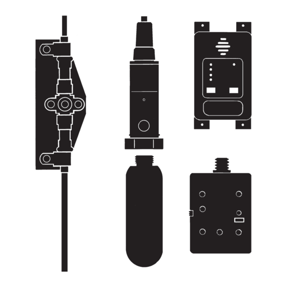
Page 44: Component Dimensions
APPENDIX CHECKFIRE MP-N Electric PAGE 38 REV. 02 2012-MAY-18 Detection and Actuation System Manual COMPONENT DIMENSIONS Required Mounting Area For Control Module, Actuator, and Control Module – Part No. 427300 Bracket 3.5 IN. 4.2 IN. (89 mm) (107 mm) 8 IN. - Page 45 CHECKFIRE MP-N Electric APPENDIX Detection and Actuation System Manual 2012-MAY-18 REV. 02 PAGE 39 COMPONENT DIMENSIONS (Continued) Spot Detector Connector Package – Part No. 416213 Spot Detector Bracket – Part No. 416221 Mounting Bracket – Part No. 423525 Spot Detector Cable Clamp –...
-
Page 46: Detection Wire Fluid Resistance Capability
DETECTION WIRE FLUID RESISTANCE CAPABILITY Resistance Rating Key: G = GOOD L = LIMITED C = CONDITIONAL (Service conditions must be outlined to ANSUL for approval of wire suitability for applications.) U = UNACCEPTABLE (Not to be used) Agent Rating Agent... - Page 48 TYCO FIRE PROTECTION PRODUCTS ONE STANTON STREET MARINETTE, WI 54143-2542...
Need help?
Do you have a question about the Checkfire MP-N and is the answer not in the manual?
Questions and answers