
Related Manuals for Worcester MT20


Summary of Contents for Worcester MT20
-
Page 1: Table Of Contents
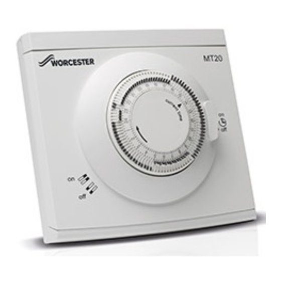
Installation and Operating Instructions Single channel mechanical timer MT20 Wired Timer Control Unit 7 733 600 332... -
Page 2: Table Of Contents
7 Operation ........8 7.1 MT20 overview......8 NOTICE indicates that material damage may occur. -
Page 3: General Safety Instructions
▶ Read and retain the operating instructions (heat source, heating controller, etc.) prior to operation. ▶ Follow the safety instructions and warnings. MT20 Wired Timer – 6 720 882 947 (2019/07) -
Page 4: Product Information
[2] Fittings pack • Screws (x2) • Wall plugs (x2) [3] Instructions Appliance compatibility The MT20 Wired Timer is compatible with the following Greenstar appliance ranges: Combi wall mounted appliances • Greenstar 8000 MT20 Wired Timer – 6 720 882 947 (2019/07) -
Page 5: Installation
Prerequisites ▶ Remove the top retainer [2] from the wall plate [1]. ▶ Ease the MT20 [3] up to release from the catches and lift 3.1.1 Installation location from the wall plate [1]. The timer should be located close to the appliance. -
Page 6: Installing The Device
▶ Ensure that there are no obstructions or other hazards before drilling. ▶ Push the MT20 [4] down into the body of the wall plate [1] to secure. ▶ Engage the tabs [2] on the top retainer [3] into the slots on the wall plate [1] and push down onto the MT20 [4] to secure. -
Page 7: Electrical Connection
– Ensure the room thermostat is set to maximum Low voltage (signal voltage) connections only. temporarily for this function test. ▶ Do not connect the MT20 to the appliance or external 230V The appliance will fire. supply. Connect the MT20 cable to the appliance. -
Page 8: Environmental Protection/Disposal
ON tappet example For additional information, please visit: (moved towards the centre) www.weee.bosch-thermotechnology.com/ OFF tappet example (moved towards outer) Table 3 Overview descriptions MT20 Wired Timer – 6 720 882 947 (2019/07) -
Page 9: Setting The Time
▶ Move the tappet inwards [3] for ON periods. Constant ▶ Move the tappet outwards [4] for OFF periods. Fig. 11 Operating mode selection Heating ON Heating OFF 0010017956-001 Fig. 10 Setting the heating times MT20 Wired Timer – 6 720 882 947 (2019/07) -
Page 10: Maintenance
Should the existing unit fail to function correctly, check: • the clock time and heating time settings are correct. • the third party room thermostat is not set too low. – Refer to manufacturers instructions for the room thermostat. MT20 Wired Timer – 6 720 882 947 (2019/07) -
Page 11: Short Operating Instructions
Fig. 13 Selecting the operating mode ▶ Move the selector switch to set required mode. – Constant ON [on] – Timed [ – Constant OFF [off] Constant Timed Constant Fig. 14 MT20 Wired Timer – 6 720 882 947 (2019/07) - Page 12 CONTROLS AND CONNECTIVITY TEAM: 0330 123 3641 APPOINTMENTS: 0330 123 9339 SPARES: 0330 123 9779 LITERATURE: 0330 123 9119 TRAINING: 0330 123 0166 SALES: 0330 123 9669 Bosch Thermotechnology Ltd. Cotswold Way, Warndon Worcester WR4 9SW United Kingdom Tel. 0330 123 9559 worcester-bosch.co.uk...
Need help?
Do you have a question about the MT20 and is the answer not in the manual?
Questions and answers