
Related Manuals for L3 comminications Stormscope II Series

Summary of Contents for L3 comminications Stormscope II Series
- Page 1 Pilot’s Guide Pilot’s Guide for the for the Stormscope Stormscope ® ® Series II Weather Mapping System Series II Weather Mapping System Model WX-1000 Model WX-1000...
- Page 2 ® Stormscope System Advantages Welcome vionics ystems, one of the world’s most experienced L-3 A companies in airborne thunderstorm avoidance instru- ments, is pleased to welcome you to the family of tens of thousands of pilots who are enjoying the benefits of safer ®...
- Page 3 Pilot’s Guide for the Stormscope ® Series II Weather Mapping System Model WX-1000 Methods and apparatus disclosed and described herein have been developed solely on company funds of L-3 Communications Avionics Systems, Inc. No government or other contractual support or rela- tionship whatsoever has existed which in any way affects or mitigates proprietary rights of L-3 Commu- nications Avionics Systems, Inc.
- Page 4 Safety Summary These warnings and cautions appear later in this guide and are repeated here for emphasis: Never use your tormscope system to attempt to penetrate a WARNING thunderstorm. The dvisory ircular, ubject: hunder- FAA A page 4-1 storms, and the irman’s nformation anual (...
- Page 5 Important Notice This guide provides general information about the operation of the WX-1000. This guide does not cover all possible interconnections with all possible types and numbers of alternate displays and customer-supplied switches. Refer to your aircraft flight manual and flight manual supplement for information specific to your aircraft.
-
Page 7: Table Of Contents
Table of Contents Section Page List of Illustrations ......vi List of Tables ........vii Chapter 1, System Description ... 1-1 General Description ............... 1-1 Processor ................1-2 Antenna ................. 1-2 Display .................. 1-2 Functional Description ............1-2 Model Definitions ..............1-4 Features ................. - Page 8 Table of Contents (continued) Section Page Chapter 4, Weather Display Interpretation . 4-1 Introduction ................4-1 Typical Patterns ..............4-2 Mapping Headings Past Thunderstorms........4-4 Special Patterns ..............4-6 Chapter 5, Specifications ....5-1 Appendix A, Heading Stabilization Option . A-1 Applicable Models ..............
-
Page 9: List Of Illustrations
List of Illustrations Figure Title Page WX-1000 Major Components ............1-1 Display With 360° View ..............1-3 Display With 120° View ..............1-3 WX-1000 Functional Diagram ............1-3 Electrical Discharges in Thunderstorms ......... 2-1 Discharge Rate a Function of Wind Shear ........2-2 Controls &... - Page 10 List of Illustrations (continued) Figure Title Page 4-12 Line of Discharge Points While Taxiing .......... 4-7 4-13 Developing Cluster Within 25 nmi ..........4-8 4-14 Split Image Off Nose of Aircraft ............ 4-8 Heading Display at Top of Screen ..........A-2 Heading Flag at Top of Screen ............
-
Page 11: Chapter 1, System Description
C h a p t e r 1 System Description General Description ® tormscope eries eather apping ystem, model II W (figure ) detects electrical discharges from WX-1000 thunderstorms up to nautical miles away and displays the thunderstorm locations relative to your aircraft. The also provides checklists and timing functions. -
Page 12: Processor
Major Components Chapter 1 – System Description is a passive system so there is no transmitter WX-1000 and no harmful transmissions. The system operates as well on the ground as in the air, thereby giving the pilot impor- tant planning information before takeoff. Processor This compact, tray-mounted computer processor receives electrical discharge information from the antenna, processes... -
Page 13: Wx-1000 Functional Diagram
Chapter 1 – System Description Functional Description M E N U 3 6 0 ° M E N U 1 2 0 ° C L E A R 2 0 0 n m C L E A R 2 0 0 n m Figure 1-2. -
Page 14: Model Definitions
Model Definitions Chapter 1 – System Description discharge signals into range and bearing data then stores the data in memory. The then displays discharges as WX-1000 storm cells as described in the next paragraph. plots a “+” symbol (discharge point) on the WX-1000 display when it detects associated discharges within the selected range and view. - Page 15 Chapter 1 – System Description Model Definitions WX-1000E (429 Navaid) This is the base model plus: • Heading stabilization • Display of navigation data from bus inputs ARINC 429 WX-1000E (429 EFIS) This is the base model plus: • Heading stabilization •...
-
Page 16: Features
Features Chapter 1 – System Description • If you have tormscope options available on your EFIS display or on your weather radar indicator, then you have a WX-1000E (429 EFIS) This guide will hereafter use the term “ ” to refer to all WX-1000 variations of the model unless otherwise indicated. -
Page 17: Chapter 2, Storm Mapping Principles
C h a p t e r 2 Storm Mapping Principles Anatomy of a Thunderstorm is intended to help pilots avoid the dangers WX-1000 associated with thunderstorms (convective wind shear, lightning, icing, tornadoes, etc.). The locates WX-1000 thunderstorms by detecting the electrical discharges that thunderstorms always generate. -
Page 18: Discharge Rate A Function Of Wind Shear
Anatomy of a Thunderstorm Chapter 2 – Storm Mapping Principles b.The friction between the opposing air currents causes electrical charges in the area to separate. As positive (+) and negative (–) electrical charges are separated, they accumulate in masses of similar charges (positive charges near the top of the cloud and negative charges near the bottom). -
Page 19: Stages Of A Thunderstorm
Chapter 2 – Storm Mapping Principles Stages of a Thunderstorm tive wind shear turbulence present. In fact, as convective wind shear increases, the rate of electrical discharges increases at an increasing rate. This relationship means that if you find the electrical discharges, you’ve found the wind shear. -
Page 20: Storm Mapping Technology
Storm Mapping Technology Chapter 2 – Storm Mapping Principles Storm Mapping Technology The WX-1000 & Weather Radar The storm mapping technology used in the WX-1000 fundamentally different than the technology used in weather radar. Weather radar operates by transmitting radio waves in the direction of interest and then receiving echoes from water droplets, whereas the operates by... - Page 21 Chapter 2 – Storm Mapping Principles Storm Mapping Technology In the ° view, the can store and display WX-1000 discharge points within the selected range. In the ° view, can store and display discharge points within WX-1000 the selected range. When the number of electrical discharges exceeds the maximum displayable capacity in a given view within a -minute interval, the oldest discharge point in...
-
Page 23: Chapter 3, Operation
C h a p t e r 3 Operation Introduction This chapter describes the ’s controls and screen WX-1000 elements, and then lists the operating instructions and error messages. Refer to the appendices for descriptions and instructions for options such as heading stabilization, navaid display, and display on an EFIS Controls &... -
Page 24: Controls & Screen Elements
Controls & Screen Elements Chapter 3 – Operation Outer Range Ring The outer range ring identifies the outer boundary of the current range. In the ° view, the outer range ring is made up of arcs spaced ° apart along a circle centered on the aircraft symbol. -
Page 25: Turn On The Wx-1000
Chapter 3 – Operation Turn On the WX-1000 Discharge Points The position of these + + + + + ++ + + + + symbols indicates the azimuth and range of the + + ++ + + + ++ + detected electrical discharge activity relative to your aircraft. -
Page 26: Adjust The Screen Brightness
Adjust the Screen Brightness Chapter 3 – Operation If the detects no faults, the screen WX-1000 SELF-TEST (figure ) displays the message ALL TESTS ARE OK After a few seconds, the display switches to the MAIN screen (figure MENU STORMSCOPE SELF-TEST WX-1000 MAIN MENU... -
Page 27: Switch To A Weather View
Chapter 3 – Operation Switch to a Weather View Switch to a Weather View The arrow symbol ( ) on screen (figures ) and in the following step means “go to.” 1. On either weather view screen or on the MAIN MENU screen (figure 3-4), press the 360°... -
Page 28: Clear All Discharge Points
Clear All Discharge Points Chapter 3 – Operation stores electrical discharge information for WX-1000 all ranges simultaneously to provide you with an instant, up-to-date display of electrical discharge activity when you select a new range. As you move from one range to the next, the range is always indicated by a solid ring to advise you of your close proximity to thunderstorms. -
Page 29: Check The Status Of The Continuous Self Test
Chapter 3 – Operation Self Tests Check the Status of the Continuous Self Test uses three types of self tests: the power-up WX-1000 self test, the continuous self test, and the operator- initiated self test. The continuous self test continuously checks for major component failures. -
Page 30: Use The Checklist Feature
Use the Checklist Feature Chapter 3 – Operation 3. Press the GO button to view the OPTIONS screen (figure 3-7). 4. Press the TEST button to run the operator-initiated self test. switches to the screen (figure WX-1000 SELF-TEST ) and begins the self test. The screen SELF TEST displays the message... -
Page 31: Checklist Menu Screen
Chapter 3 – Operation Use the Checklist Feature You can create as many as separate checklists, each containing a maximum of lines, with a maximum of characters per line. It’s solely your responsibility to select appropriate checklist items. One of the following symbols appears in front of each checklist item: •... -
Page 32: Skipped Item
Use the Checklist Feature Chapter 3 – Operation 5. Press the GO button to view the items in the selected checklist (figure 3-10). B E F O R E L A N D I N G The first unchecked item in F U E L T Y - C H E C K the checklist is highlighted. -
Page 33: Set The Date And Time
Chapter 3 – Operation Set the Date & Time 8. To scroll backwards and review the checklist at any time, press the BACKUP button. Set the Date & Time 1. Press the MENU button to go to the MAIN MENU screen (figure 3-4). -
Page 34: Measure Elapsed Time
Measure Elapsed Time Chapter 3 – Operation 2. Press the NEXT button repeatedly if necessary until the “Time/Date” item is highlighted. 3. Press the GO button to view the TIME/DATE screen (figure 3-13). The stopwatch digits should be highlighted. 4. Press the START button to start the stopwatch. 5. -
Page 35: Turn Off The Wx-1000
Chapter 3 – Operation Turn Off the Stormscope System Turn Off the WX-1000 1. Rotate the OFF/BRT knob counterclockwise until it turns off. Power turns off to the display, processor, and WX-1000 antenna, and all discharge points are erased from memory. Error Messages detects most common faults and displays error WX-1000... -
Page 36: Error 44
Error Messages Chapter 3 – Operation ERROR 44 or 45: Weather mapping is inhibited (figure 3-15) There may or may not be an error in the Meaning: thunderstorm processing circuitry of the unit. Seventy percent of these errors are caused by aircraft noise. Other causes include flying near power transmitters, taxiing over underground cables, or operating near a hangar, power lines, or... -
Page 37: Error 46
Chapter 3 – Operation Error Messages ERROR 46: Weather mapping is inhibited (figure 3-16) This error typically means that the Meaning: WX-1000 antenna is not able to receive or forward thunderstorm data; but this error could instead be caused by noise or by a faulty processor. -
Page 39: Chapter 4, Weather Display Interpretation
C h a p t e r 4 Weather Display Interpretation Never use your tormscope system to attempt to penetrate a WARNING thunderstorm. The dvisory ircular, ubject: hunder- FAA A storms, and the irman’s nformation anual ( ) recom- mend that you “avoid by at least miles any thunderstorm identified as severe or giving an intense radar echo.”... -
Page 40: Typical Patterns
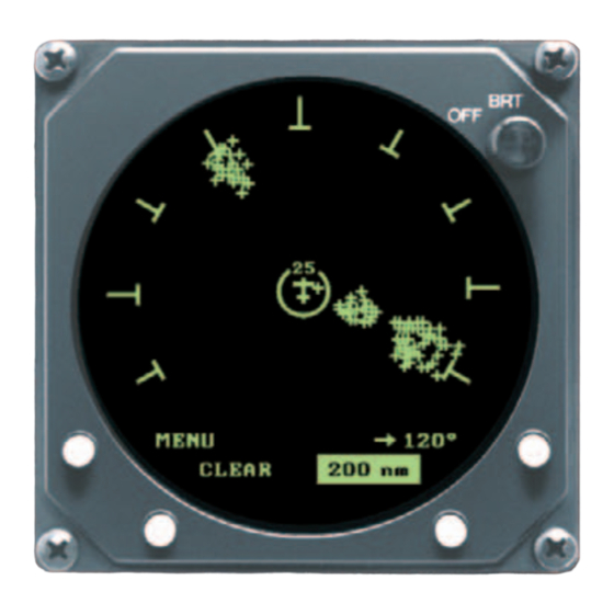
Typical Patterns Chapter 4 – Weather Display Interpretation monitored by the . Areas of gray or black indicate WX-1000 thunderstorms. The darker the area, the greater the rate of electrical discharge activity. Typical Patterns Three Clusters within the 200 nmi Range Ring Figure shows the °... -
Page 41: Three Clusters Within 200 Nmi
Chapter 4 – Weather Display Interpretation Typical Patterns M E N U 1 2 0 ° MENU 120° C L E A R 2 0 0 n m CLEAR 100 nm Figure 4-3. Range Changed to Figure 4-2. Three Clusters Within 100 nmi 200 nmi M E N U... -
Page 42: Mapping Headings Past Thunderstorms
Mapping Around Storms Chapter 4 – Weather Display Interpretation has fewer discharge points than the cluster at , indicating 5:30 a lower rate of electrical activity. Both clusters must be avoided. Mapping Headings Past Thunderstorms Figures through and the following paragraphs show the progression of an aircraft past several thunderstorms. -
Page 43: Range Set At 200 Nmi
Chapter 4 – Weather Display Interpretation Mapping Around Storms MENU 120° M E N U 1 2 0 ° CLEAR C L E A R 2 0 0 n m Figure 4-5. Range Set at 200 nmi Figure 4-6. Aircraft Progresses 100 nmi M E N U 3 6 0 °... -
Page 44: Special Patterns
Special Patterns Chapter 4 – Weather Display Interpretation Special Patterns Randomly Scattered Discharge Points Atmospheric instability associated with cumulus clouds, or developing or dissipating thunderstorms could cause randomly scattered discharge points as shown in figure . If you observe random discharge points, continue to monitor the screen for developing clusters which indicate thunderstorm activity. -
Page 45: Discharge Points Off The Aircraft's Nose
Chapter 4 – Weather Display Interpretation Special Patterns nmi range. Switch to the other ranges to ensure that there is no thunderstorm activity along your intended path. Note that the plots every electrical discharge WX-1000 detected within the nmi range at the exact location detected unless the discharge is associated with a cluster of discharges, in which case the discharge point is clustered with the associated discharge points. -
Page 46: Developing Cluster Within 25 Nmi
Special Patterns Chapter 4 – Weather Display Interpretation Similar concentrations of discharge points across the screen may appear while taxiing due to electrical signals from nearby equipment such as arc welders or subway rails. After passing the source of the interference, press the button. -
Page 47: Chapter 5, Specifications
C h a p t e r 5 Specifications Table 5-1. WX-1000 Processor Specifications* Part Number Definition: 78-8060-5790-3 – WX-1000 78-8051-9160-4 – WX-1000+ 78-8060-5941-2 – WX-1000E (232/422 navaid) 78-8060-6086-5 – WX-1000E (429 EFIS) 78-8060-6092-3 – WX-1000E (429 navaid RX low/TX low) 805-11000-001 –... - Page 48 Processor Specifications Chapter 5 – Specifications Table 5-1. WX-1000 Processor Specifications* (Continued) Operating Altitude: 55,000 ft maximum TSO Compliance: C110a RTCA Compliance: Environmental: DO-160B F2-BA(BMNO)XXXXXXZ(AB)A(AZ)ZZZXXX Software: DO-178A Level 2 *Specifications subject to change without notice. ® Stormscope WX-1000 Pilot’s Guide...
- Page 49 Chapter 5 – Specifications Display Specifications Table 5-2. WX-1000 Display Specifications* Part Number Definition: 78-8060-5900-8 – Black Bezel 78-8060-5900-9 – Gray Bezel Size: 3.37 in (8.56 cm) high 3.37 in (8.56 cm) wide 8.24 in (20.92 cm) deep Weight: 2.5 ±0.2 lb (1.1 ±0.1 kg) Power Input Requirements: +15/-15 V dc, 0.7 A (maximum) Operating Temperature:...
- Page 50 Antenna Specifications Chapter 5 – Specifications Table 5-3. WX-1000 Antenna Specifications* Part Number Definition: 78-8051-9200-8 – White 78-8051-9220-6 – Black Size: 1.13 in (2.87 cm) high 4.49 in (11.40 cm) wide 10.06 in (25.60 cm) deep Weight: 1.9 lb (0.86 kg) Operating Temperature: -55 to +70 °C (-67 to +158 °F) Storage Temperature:...
- Page 51 A p p e n d i x Heading Stabilization Option Applicable Models The following tormscope models contain the heading stabilization option: WX-1000+ WX-1000E (all variations) The heading stabilization option must be installed on a to create a before the navaid or option 1000 WX-1000+...
-
Page 52: Appendix A Heading Stabilization Option
Heading Options Appendix A Heading Stabilization Option 0 5 7 ° FLAG M E N U 3 6 0 ° MENU 360° C L E A R 0 5 0 n m CLEAR 050 nm Figure A-1. Heading Display at Figure A-2. -
Page 53: Options Screen With Heading Stabilization
Appendix A – Heading Stabilization Option Heading Error Message O P T I O N S E R R O R 1 1 C o n t i n u o u s T e s t : H D G S t a b i l i z a t i o n : H e a d i n g s t a b i l i z a t i o n H e a d i n g D i s p l a y : i s n o t a v a i l a b l e... -
Page 55: Applicable Models
A p p e n d i x B Navaid Option Applicable Models The following tormscope models contain the navaid option: WX-1000E (232/422 navaid) WX-1000E (429 navaid) The navaid option can only be installed on a WX-1000 Once the navaid option is installed, the model number of the unit changes to one of the above model numbers. -
Page 56: General Description
General Description Appendix B – Navaid Option 0 2 2 ° 0 9 9 . 8 B J J K T S 1 4 0 0 3 6 ° E T E B R G 0 0 : 4 2 0 3 6 °... -
Page 57: Main Menu W/Navaid
Appendix B – Navaid Option Main Menu Main Menu The navaid option adds the “ avaid isplay” item to the main menu (figure ). The “ avaid isplay” item allows you to remove navaid-related items from the weather views as follows: 1. - Page 58 Navaid Setup Screen Appendix B – Navaid Option played. The navaid data items can be changed regardless of whether the avaid isplay item on the main menu is set to The six navaid data items currently selected are displayed in the middle portion of the avaid etup screen in the same arrangement as they would appear on the weather...
- Page 59 Appendix B – Navaid Option Navaid Setup Screen 3. Press the GO button to view the OPTIONS screen. 4. Press the NEXT button repeatedly if necessary until “ Navaid Setup” is highlighted. 5. Press the GO button to view the Navaid Setup screen. 6.
-
Page 60: Data Comm Errors
Data Comm Errors Appendix B – Navaid Option Data Comm Errors Error (figure means receiving no data. Error indi- E R R O R 1 3 cates a processing C o m m u n i c a t i o n e r r o r error. -
Page 61: Appendix C, Efis Option
A p p e n d i x EFIS Option Applicable Models Only the ) model contains the WX-1000E 429 EFIS EFIS option. The option can only be installed on a EFIS +. Once the option is installed, the unit’s model 1000 EFIS number changes to... - Page 63 Record of Important Information Dealer Information Name _________________________________________ Address ________________________________________ City, State, Zip __________________________________ Telephone ______________________________________ Equipment Information Date of Purchase _________________________________ Installation Date _________________________________ Processor: Model Number _______________________________ Part Number ________________________________ Serial Number _______________________________ Mod Letter __________________________________ Software Version _____________________________ Antenna: Model Number _______________________________ Part Number ________________________________...
- Page 64 This data is provided at no charge, or at cost, to the public and is considered publicly available, No License Required (NLR) as defined in the Export Administration Regulations (EAR) Part 734.7-11. 75-0299-7690-1 (Rev. E, 05/03/07) L-3 Communications Avionics Systems, Inc. Stormscope WX-1000 ®...
Need help?
Do you have a question about the Stormscope II Series and is the answer not in the manual?
Questions and answers