Advertisement
Quick Links
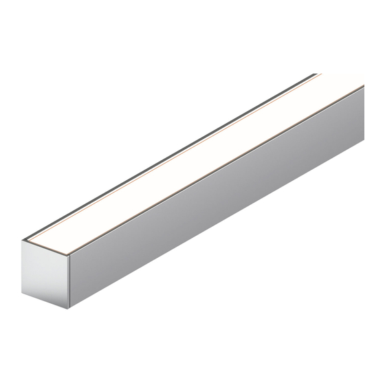
KM, KS, KXL & KL Channel -
Models KMC-XX, KSC-XX, KXLC-XX, & KLC-XX
Please read all instructions prior to installation and keep for future reference!
1. Product to be installed by a qualied electrician.
2. Prior to installation ensure power is off at fuse box to prevent electrical shock.
1
fixture
1.1
4"
every 30"
surface
Note:
Prior to install, 24VDC power must be present for wiring. Also
review and account for all parts necessary to install properly.
1.1 Snap the lens into the extrusion, then align & center the extrusion to the
determined location. Then make any reference marks if needed to install
the extrusion, reference step 3 for mounting options.
3
3.1 Secure the extrusion to the surface by either mounting directly with
screws or using mounting brackets.
a. If mounting extrusion with screws:
the extrusion followed by screwing directly to the surface.
b. If mounting extrusion with brackets :
install a bracket 4" from each end, followed by installing one every
30". Then secure, by screwing through the bracket to the surface.
For
adjustable mounting brackets
end, followed by installing one every 30". Then secure, by slightly
loosening the 2 screws on the side of each adjustable bracket.
Then secure, by screwing through bracket to the surface. Then
rotate to the desired position, followed by tightening the side
screws.
FIXED BRACKET
30" maximum spacing
of mounting brackets
mounting brackets
3.1
#4 flat head
wood screws
*LUMINII RESERVES THE RIGHTS TO CHANGE SPECIFICATION & INSTRUCTION WITHOUT NOTICE
Installation Instructions
mounting
bracket
4"
Make counter sunk holes through
For
fixed mounting brackets
,
, install a bracket 4" from each
MOUNT EXTRUSION
WITH MOUNTING BRACKETS
2
lens
2.1
extrusion
Caution:
Safety equipment is recommended, when modifications are being
made to the extrusion & lens.
2.1 Extrusion & lens can be cut in the field. Using the proper blade for
aluminum, cut to the desired length.
drill through
countersink
extrusion for
the holes
mounting
holes
extrusion
STEP A
3.1
30.0"
4.0"
extrusion
MOUNT EXTRUSION
WITH SCREWS
loosen screws
30" maximum spacing
of mounting brackets
7777 Merrimac Ave
Niles, IL 60714
T 224.333.6033
F 224.757.7557
info@luminii.com
www.luminii.com
Page 1 of 2
2.1
miter saw
tighten screws below
extrusion surface
before installing LineLED
STEP B
STEP C
30.0"
install #4 flat head wood
screws a maximum 30"
apart minimum of 2
screws per extrusion.
ADJUSTABLE BRACKET
flathead screw
3.1
REV0.2 09062018
4.0"
Advertisement

Related Manuals for luminii KMC Series


Summary of Contents for luminii KMC Series
-
Page 1: Installation Instructions
ADJUSTABLE BRACKET 30" maximum spacing flathead screw of mounting brackets mounting brackets #4 flat head 30" maximum spacing wood screws MOUNT EXTRUSION of mounting brackets WITH MOUNTING BRACKETS REV0.2 09062018 *LUMINII RESERVES THE RIGHTS TO CHANGE SPECIFICATION & INSTRUCTION WITHOUT NOTICE... - Page 2 8.1 Ensure the correct (wattage & voltage) power supply is used to power LineLED. Then proceed to connect LineLED wires from extrusion to power supply. For more information please refer to power supply and LineLED wiring instructions. REV0.2 09062018 *LUMINII RESERVES THE RIGHTS TO CHANGE SPECIFICATION & INSTRUCTION WITHOUT NOTICE...
Need help?
Do you have a question about the KMC Series and is the answer not in the manual?
Questions and answers