Yamaha PM 5000 Series Service Manual
Hide thumbs
Also See for PM 5000 Series:
- Owner's manual (106 pages) ,
- Block diagram (2 pages) ,
- Owner's manual (2 pages)
Table of Contents
Advertisement
Quick Links
Download this manual
See also:
Owner's Manual
PM5000-52C
PM5000-36
PM5000-28
PA
011697
PM5000-52C: 200307-オープンプライス
PM5000-36: 200307-オープンプライス
PM5000-28: 200307-オープンプライス
MIXING CONSOLE
SERVICE MANUAL
CONTENTS
(目次)
(総合仕様)
CONNECTOR PIN ASSIGNMENTS
(寸法図)
(ICブロック図)
IC BLOCK DIAGRAM
(シート基板図)
CIRCUIT BOARDS
INSPECTIONS
(検査)
................................................... 252/279
(テストプログラム)
TEST PROGRAM
MEMORY WRITE METHOD
(メモリー書込み方法)
................................................... 346/351
INITIALIZING THE INTERNAL MEMORY
(内部メモリーの初期化)
(エラーメッセージ)
ERROR MESSAGES
MIDI DATA FORMAT
(MIDIデータフォーマット)
MIDI IMPLEMENTATION CHART
(MIDIインプリメンテーションチャート)
PARTS LIST
OVERALL CONNECTOR CIRCUIT DIAGRAM
(総コネクター接続回路図)
(回路図)
CIRCUIT DIAGRAM
BLOCK & LEVEL DIAGRAM
Copyright (c) Yamaha Corporation. All rights reserved. PDF-K19441
................................................... 3
.................................................. 6
.................................... 7
.......................................................... 14
(ユニットレイアウト)
................................. 34/38
(分解手順)
............................ 42
................................ 96
................................ 102
..................................... 107
.......................... 306/326
...................................................... 356
........................... 357
............................ 360
(ブロック&レベルダイアグラム)
HAMAMATSU, JAPAN
PM5000-52C
............... 15
. 26/30
............... 358
'03.09
Advertisement
Table of Contents

Related Manuals for Yamaha PM 5000 Series


Summary of Contents for Yamaha PM 5000 Series
-
Page 1: Table Of Contents
....358 MIDI IMPLEMENTATION CHART (MIDIインプリメンテーションチャート) ......360 PARTS LIST OVERALL CONNECTOR CIRCUIT DIAGRAM (総コネクター接続回路図) (回路図) CIRCUIT DIAGRAM BLOCK & LEVEL DIAGRAM (ブロック&レベルダイアグラム) 011697 HAMAMATSU, JAPAN PM5000-52C: 200307-オープンプライス PM5000-36: 200307-オープンプライス Copyright (c) Yamaha Corporation. All rights reserved. PDF-K19441 ’03.09 PM5000-28: 200307-オープンプライス... - Page 2 IMPOR TANT NOTICE This manual has been provided for the use of authorized Yamaha Retailers and their service personnel. It has been assumed that basic service procedures inherent to the industry, and more specifically Yamaha Products, are already known and under- stood by the users, and have therefore not been restated.
-
Page 3: Specifications
PM5000 (総合仕様) SPECIFICATIONS (一般仕様) 1. General Specifications 0dBu is referenced to 0.775 Vrms. Total Harmonic Distortion Less than 0.1% 20Hz〜20kHz @ +14dBu 600Ω (Master Output) (THD+N) (Input Gain Control at Maximum) Frequency Response 0+1,-3dB 20Hz〜20kHz @ +4dBu 600Ω (Master Output) (Input Gain Control at Maximum) Hum & Noise (20Hz〜20kHz) -128dBu Equivalent Input Noise. Rs=150Ω -100dBu Residual Output Noise. Input Gain=Maximum -92dBu (96dB S/N) STEREO AUX Master fader at nominal level and all assign SW s off. Input Pad=OFF -87dBu (91dB S/N) GROUP/AUX Master fader at nominal level and all assign SW s off. Input sensitivity=-60dBu -92dBu (96dB S/N) STEREO, MONO (C) Master fader at nominal level and all assign SW s off. -64dBu (68dB S/N) STEREO AUX, GROUP/AUX, STEREO, MONO (C) Master fader and one input fader at nominal level. - Page 4 PM5000 Dimensions Width 28ch 1432 mm 36ch 1671 mm 52ch 2148 mm Depth 1113 mm Height 349 mm Weight 28ch 153 kg 36ch 179 kg 52ch 228 kg *1 Hum & Noise are measured with a 6dB/octave filter @ 12.7kHz; equivalent to a 20kHz filter with infinite dB/octave attenuation. Temperature condition @+10〜+25℃ *2 PAN/BAL: the left or the right turning around. *3 Turn over/roll-off frequency of shelving: 3dB below maximum variable level. (入出力特性) 2. Inputs/Outputs (入力仕様)...
- Page 5 PM5000 (出力仕様) 2.2 Output Characteristics Actual Output Level For Use With Connection Source Connector In Mixer Nominal Nominal Max. before Clip Impedance STEREO AUX OUT (1〜12)[L, R] GROUP/AUX OUT (1〜8) STEREO OUT [L, R] MONO (C) OUT 150Ω 600ΩLines +4dBu (1.23V) +24dBu (12.3V) XLR-3-32 type STEREO MATRIX OUT (1〜4) [L, R] MATRIX OUT (1〜8) MONITOR OUT (A B) [L, R] TB/OSC OUT MONO IN DIRECT OUT 1〜n ch *1 150Ω 600ΩLines +4dBu (1.23V) +24dBu (12.3V) Phone Jack (TRS) *1...
-
Page 6: コネクターピンアサイン表
PM5000 (コネクターピンアサイン表) CONNECTOR PIN ASSIGNMENTS The connector diagrams refer to the console connectors. (各コネク タ ー図は、 本体側のコネク タ ーのピン配列を示します。 ) (CASCADEコネクター) Cascade Connector (CASCADE TYPE Bピン アサイ ン) CASCADE TYPE B Pin Assignments (D-sub 25-pin Connector) 13 12 11 10 25 24 23 22 21 20 19 18 17 16 15 14 Pin # Function Pin # Function VCA EXT 1... -
Page 7: Panel Layout (パネルレイアウト
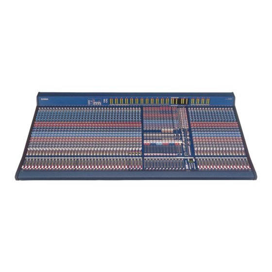
PM5000 (パネルレイアウト) PANEL LAYOUT Top Panel (トップパネル) PM5000-52C/36 PM5000-52C PM5000-36 PM5000-52C only PM5000-28 PM5000-28 q Input Channel Section (インプットチャンネルセクション) w Master Output Section (マスターアウトセクション) e Matrix Send and Master Out Section (マトリクスセンド&マスターアウトセクション) r VCA Master Section (VCA マスターセクション) t Oscillator/Talkback Section (オシレーター... - Page 8 PM5000 Rear Panel (リアパネル) PM5000-52C/36 PM5000-52C PM5000-36 PM5000-52C only PM5000-28 !1 Mono (Stereo) Inputs (モノラル(ステレオ)インプット) !2 Sub Inputs (サブイン) !3 Insert Inputs and Outputs (インサートイン & アウト) !4 Stereo Aux Master Out (ステレオ AUX マスターアウト) !5 G/A (Group/Aux) Master Out (G/A (グループ /AUX )マスターアウト) !6 Matrix Out (マトリクスアウト)...
- Page 9 PM5000 Head Amp Block HPF Block (ヘッドアンプブロック) (HPF ブロック) Mono Input Module Stereo Input Module q [+48V] Switch (モノラルインプットモジュール) (ステレオインプットモジュール) (+48V スイッチ) w [PAD] Switch (PAD スイッチ) e [GAIN] Control (GAIN ノブ) r [L+R] Switch (stereo modules only) y [HPF] Switch and Control (L+R スイッチ (HPF スイッチ&ノブ) (ステレオインプット...
- Page 10 PM5000 G/A (Group/Aux) Send 1~8 Block Main Out Block (メインアウトブロック) (G/A (グループ /AUX )センドブロック 1 〜 8) Mono Input Module Stereo Input Module (モノラルインプットモジュール ) (ステレオインプットモジュール) !7 [PAN]/[CSR] Control (PAN & CSR ノブ (mono modules only) (モノラルインプットモジュールのみ) ) !8 [BAL] Control (BAL ノブ (stereo modules only) (ステレオインプットモジュールのみ) ) !9 Main Out Switches !4 Send Level Controls (メインアウトスイッチ)...
- Page 11 PM5000 Controls Common To All Masters (各マスターモジュールに共通のコントロール) Master output Section (マスターアウトセクション) Odd-numbered Even-numbered Odd-numbered Even-numbered Master Controls Master Controls Master Controls Master Controls 奇数番号のマスター用 偶数番号のマスター用 奇数番号のマスター用 偶数番号のマスター用 コントロール コントロール コントロール コントロール Stereo Aux Master Module G/A (Group/Aux) Master Module Stereo/Mono Master Module (ステレオ...
- Page 12 PM5000 Matrix Send and Master Out Section (マトリクスセンド&マスターアウトセクション) Matrix Send Matrix Master Section Out Section (マトリクス (マトリクス センド マスターアウト セクション) セクション) [TO MATRIX] switch ([TO MATRIX] スイッチ) MONO MODE Indicator Monitor Control Section ([MONO MODE] インジケーター) (モニターコントロールセクション) Matrix [ON] Switch (Matrix [ON] スイッチ) INPUT CUE TRIM knob (INPUT CUE TRIMノブ)...
- Page 13 PM5000 Digital Control Section (デジタルコントロールセクション) q Scene Display (3 Digits + 3 Dots) (シーンディスプレイ(3 桁+ 3 つのドット) ) w Message Display (4 Characters) (メッセージディスプレイ(4 桁) ) e Parameter Display (12 Characters) (パラメーターディスプレイ(12 桁) ) r [RECALL] Switch (RECALL スイッチ) t [RECALL UNDO] Switch (RECALL UNDO スイッチ) y [STORE] Switch (STORE スイッチ)...
-
Page 14: Dimensions
PM5000 (寸法図) DIMENSIONS PM5000-28 PM5000-36 Rear view Rear view 841.8 482.6 1080.2 482.6 SIde view SIde view Top view Top view 348.1 348.1 1432 1671 Front view Front view Units: mm Units: mm (単位) (単位) PM5000-52C Rear view 1080.2 475.3 484.2 SIde view Top view... -
Page 15: Circuit Board Layout
PM5000 (ユニットレイアウト) CIRCUIT BOARD LAYOUT MONO INPUT MODULE (MONO INPUT モジュール) <Left side view> INHA 1/2 INSEND 1/9 INSUB 1/7 INSUB 2/7 <Right side view> INSUB 3/7 INHA 2/2 INSEND 2/9 INSEND 1/9 INSEND 3/9 INHA 1/2 <Top view> INSEND 1/9 INHA 1/2 INSUB 3/7 INSUB 1/7... - Page 16 PM5000 STEREO INPUT MODULE (ST INPUT モジュール) <Left side view> SISEND 1/9 SIHA 1/3 SISUB 1/7 <Right side view> SISUB 2/7 SISUB 3/7 SIHA 1/3 SISEND 2/9 SISEND 1/9 SISEND 3/9 SIHA 2/3 SIHA 3/3 SISEND 1/9 <Top view> SIHA 1/3 SISUB 3/7 SISUB 1/7 SISUB 4/7~7/7...
- Page 17 PM5000 STEREO AUX MASTER MODULE (ST AUX マスターモジュール) <Left side view> SAMAS1 SAMAS2 1/8 SAMASSUB 1/17 SAMAS2 4/8 <Right side view> SAMASSUB SAMASSUB SAMAS2 2/17~5/17 6/17~9/17 5/8~8/8 SAMAS2 1/8 SAMAS2 2/8 SAMAS1 SAMAS1 SAMAS1 SAMAS2 1/8 SAMAS1 <Top view> SAMASSUB 1/17 SAMAS2 4/8 SAMASSUB SAMASSUB...
- Page 18 PM5000 GROUP/AUX MASTER MODULE (G/A マスターモジュール) <Left side view> GAMAS2 1/8 GAMAS1 GAMAS2 4/8 GAMASSUB 1/17 GAMAS2 3/8 <Right side view> GAMASSUB GAMASSUB GAMAS2 10/17~13/17 14/17~17/17 5/8~8/8 GAMAS2 1/8 GAMAS1 GAMAS2 2/8 GAMAS1 GAMAS1 <Top view> GAMAS2 1/8 SAMAS1 GAMASSUB 1/17 GAMAS2 4/8 GAMASSUB GAMASSUB...
- Page 19 PM5000 STEREO/MONO MASTER MODULE (ST/MONO マスターモジュール) <Left side view> STMAS2 1/8 STMAS1 STMASSUB 3/16 <Right side view> STMASSUB 1/16 STMAS1 STMAS2 1/8 STMASSUB 2/16 STMAS2 2/8 STMAS1 STMAS1 STMASSUB 4/16 STMASSUB STMASSUB 9/16~16/16 5/16~8/16 <Top view> STMAS2 1/8 STMAS1 STMASSUB 1/16 STMASSUB 2/16 STMASSUB 3/16...
- Page 20 PM5000 MONITOR MODULE (MONITOR モジュール) <Left side view> MONI2 1/3 MONI1 <Right side view> MONI2 2/3 MONISUB 2/13~13/13 MONISUB 1/13 MONI2 3/3 MONI2 1/3 MONI1 MONI1 MONI1 <Top view> MONI2 1/3 MONI1 MONI2 2/3 MONISUB 2/13~13/13...
- Page 21 PM5000 TOP PANEL (トップパネル)...
- Page 22 PM5000 REAR PANEL (リアパネル)...
- Page 23 PM5000 MAIN FRAME ASSEMBLY (メインフレーム Ass y)...
- Page 24 PM5000 MAIN FRAME ASSEMBLY (メインフレーム Ass y)...
- Page 25 PM5000 METER PANEL ASSEMBLY (メーターパネル Ass y)...
-
Page 26: Installing Option (オプション製品の取り付け方法
PM5000 INSTALLING OPTIONS The following optional (sold separately) modules and Module Removal and Replacement transformer are available: The procedure for removal of top-panel modules is the Input Section Modules same for the input and master section. • MNM5000: Monaural input module. •... - Page 27 PM5000 Removing Rear Panel Input Units Unplug the wiring connectors at the top (rear) end of the module that connect the module to the rear panel. When removing rear-panel input units that correspond to There are two connectors on both mono and stereo each mono and stereo input channel (these are available modules, but their locations are slightly different.
- Page 28 PM5000 Module Installation Input Transformer Installation The module installation procedure is the reverse of the removal procedure described above. The PM5000 input modules feature electronically balanced inputs that do not normally require any additional isolation. If you would rather have Rear Panel Input Units conventional transformer-isolated balanced inputs, First pass the wiring through the opening in the rear...
- Page 29 PM5000 Mono Input Module Transformer leads Shield Brown Brown White White YAMAHA CN202 CN201 R106 Bottom stay R104 Transformer R105 XK367 Stereo Input Module Remove (unplug) the existing small circuit board from the module, and replace it with the circuit board now soldered to the transformer leads.
- Page 30 PM5000 オプション製品の取り付け方法 オプシ ョ ン (別売品) には、 以下のモジュール/ ト ラ ンスが モジュールの取り外し/取り付け方 用意されています。 ト ッ プパネル上のモジュールの取り外し方は、 イ ンプ ッ ト モ ● インプット部オプション ジュールとマス タ ーモジュールで同じです。 ・ MNM5000: モノ ラルイ ンプ ッ ト モジュール ・ MNR5000: モノ ラルイ ンプ ッ ト モジュール用 ●...
- Page 31 PM5000 ● インプットリアパネルの取り外し方 モジュール上側に結線してある接続線のコネク タ ーを抜き ます。 コネク タ ーは2ヶ所あ り、 モノ ラルと ステ レオのモジュー イ ンプ ッ ト モジュールオプシ ョ ンであるモノ ラルまたはステ ルで位置が若干異なり ます。 リ アパネルからの接続線をす レオのイ ンプ ッ ト リ アパネルを取り外すと きは、 対応してい べてのコネク タ ーから抜いてく だ さい。 るモジュールを一度外して、...
- Page 32 PM5000 ● モジュールの取り付け方 インプットトランスフォーマー モジュールの取付は、 取り外し方と逆の手順で行ないます。 の取り付け方 インプットリアパネルの取り付け方 PM5000のイ ンプ ッ ト モジュールは電子バラ ンス式です。 (インプットモジュールの場合) 通常使用時において、 イ ンプ ッ ト に対するアイ ソ レーシ ョ ン を考え る必要はあ り ません。 しかし従来のイ ンプ ッ ト ト ラ ン 最初に、 接続線を リ アパネルから コ ン ソ ール本体のプラ ス ス...
- Page 33 PM5000 モノラルインプットモジュール トランスからの線 シールド 茶 シロ 赤 アカ シロ YAMAHA CN202 CN201 アカ R106 ボトムステー R104 トランス R105 XK367 ステレオインプットモジュール 現行の基板を取り外し、 その位置に ト ラ ンスに取り付けた 新しい基板と差し替え ます。 次に付属のケーブルク ラ ンプ を使って、 線材を ま とめて束ねて、 残った部分をニッパーな どで切ってく だ さい。 モノラルインプットモジュール ボトムステー ...
-
Page 34: Changing Internal Switch Settings
PM5000 CHANGING INTERNAL SWITCH SETTINGS Internal Switch Settings For Each module As you tell from the PM5000 block diagram, each module has a number of internal switch settings. These settings can be changed to “customize” the PM5000 signal flow to most ideally suit your mixing requirements. The chart below lists the switches and their functions. - Page 35 PM5000 Internal Switch Locations On Each module Mono Input Module Remove these screws and the bracket. Replace after making the required switch set ings. POST POST POST Stereo Input Module SW105 POST Remove these screws and L&R L-ONLY the bracket. Replace after making the required switch Ø...
- Page 36 PM5000 Stereo/Aux Master Module STAUX.GA (ODD) STAUX.GA (EVEN) Printing MATRIX SW102 SW103 SW105 SW106 Switches SW102 SW103 SW105 SW106 G/A Master Module GA (ODD) GA (EVEN) POST POST TO ST ON SW ON SW SW101 SW104 STAUX.GA (ODD) STAUX.GA (EVEN) Printing MATRIX SW102...
- Page 37 PM5000 Stereo/Mono Master Module TO MATRIX MONO MASTER MASTER Printing SW102 SW103 SW105 SW106 Switches SW102 SW103 SW105 SW106...
-
Page 38: インナースイッチの切り替え方法
PM5000 インナースイッチの切り替え方法 各モジュールのインナースイッチの設定 ブロ ッ ク ダイ アグ ラ ムを見ていただければわかる よ う に、 各モジュールにはいくつかのイ ンナース イ ッチがあ り ます。 このイ ン ナース イ ッチの変更によ り、 特定の信号経路を変更する こ とができ ます。 下表はそのス イ ッチと動作の関係です。 いくつかのス イ ッチは2つの組み合わせで動作する ものも あ り ます。 ブロ ッ ク ダイ ア グ... - Page 39 PM5000 各モジュールのインナースイッチの位置 モノラルインプットモジュール このねじを外して 金具を取り外す。 スイッチの変更終了後は 元に戻します。 POST POST POST ステレオインプットモジュール SW105 POST このねじを外して L&R L-ONLY 金具を取り外す。 Ø SW MODE スイッチの変更終了後は 元に戻します。 ...
- Page 40 PM5000 ステレオ/AUXマスターモジュール STAUX.GA (ODD) STAUX.GA (EVEN) プリント MATRIX SW102 SW103 SW105 SW106 スイッチ SW102 SW103 SW105 SW106 G/Aマスターモジュール GA (ODD) GA (EVEN) POST POST TO ST ON SW ON SW SW101 SW104 STAUX.GA (ODD) STAUX.GA (EVEN) プリント MATRIX SW102 SW103 SW105 SW106...
- Page 41 PM5000 STEREO/MONO マスターモジュール TO MATRIX MONO MASTER MASTER プリント SW102 SW103 SW105 SW106 スイッチ SW102 SW103 SW105 SW106...
-
Page 42: Disassembly Procedure
PM5000 (分解手順) DISASSEMBLY PROCEDURE Plate Module 8, 16, 24, 32, 52 (プレートモジュール8、16、24、32、52) ........... 43 Plate Fader8, 16, 24, 32, 52 (プレートフェーダ8、16、24、32、52) ............43 Fader IN 16, IN 8 Assemblies (フェーダーIN16/IN8 Ass y) ................45 (INFADシート、モーターフェーダー) INFAD Circuit Board and Fader Motor .......... - Page 43 PM5000 プレートモジュール 8、16、24、32、52 Plate Module 8, 16, 24, 32, 52 (所要時間:約 3 分) (Time required: About 3 minutes) 1-1. Remove the screws marked [270A]. Then remove 1-1. [270A]のネジを外してプレートモジュール 8、16、 the plate module8, 16, 24, 32, 52. (Fig.1) 24、32、52 を外します。 (図 1) [270A]: PM5000-52C 13 本...
- Page 44 PM5000 Fig .2 (図2)
- Page 45 PM5000 フェーダー IN16/IN8 Ass y 部 Fader IN 16 Assembly Section フェーダー IN16/IN8 Ass y Fader IN 16, IN 8 Assemblies (所要時間:約 5 分) (Time required: About 2 minutes) 3-1. Remove the Plate module. (See procedure 1.) 3-1. プレートモジュールを外します。 (1 項参照) 3-2. Remove the Plate fader.
- Page 46 PM5000 Fader IN 16 Assembly (フェーダー IN 16 Ass y) [240A] [240A] [240A] [240A] [240A] [240A] [30A] [60A] Fader moter (モーターフェーダー) Fader knob (フェーダーノブ) [60A] [240A] [240A] [240A] [240A] [240A] [240A] INFAD [30A] [30A]: Flat Head Screw (+皿小ネジ) 3.0X6 MFZN2BL (EC030030) (+皿小ネジ) [60A]: Flat Head Screw 3.0X6 MFZN2BL (VS182000) [240A]: Flat Head Screw (+皿小ネジ)...
- Page 47 PM5000 INFAD シート、VCAFAD シート、 INFAD Circuit Board, VCAFAD Circuit Board and KEY Circuit Board KEY シート (所要時間:約 3 分) (Time required: About 3 minutes) 6-1. フェーダー VCA Ass y を外します。 (5 項参照) INFAD シート 6-1. Remove the fader VCA assembly. (See procedure 5.) 6-2.
- Page 48 PM5000 フロントパッド Front Pad (所要時間:約 9 分) (Time required: About 9 minutes) 7-1. Remove the fader IN 16 assembly. (See procedure 3.) 7-1. フェーダー IN 16 Ass y を外します。 (3 項参照) 7-2. Remove the fader VCA assembly. (See procedure 4.) 7-2. フェーダー VCA Ass y を外します。 (4 項参照) 7-3.
- Page 49 PM5000 PM5000-52C PM5000-36 [290] PM5000-28 PM5000-36/28 only <Top view> Top cover (トップカバー) [290] <Left side view> Pad corner front L Pad corner front R Front pad (フロントパッド) [286] (パッドコーナーフロントL) (パッドコーナーフロントR) Holde, Front pad x 5 [550] [550] [550] <Front view> (金具フロントパッド) Front pad [570A] [570A] [570B] [570A] [570A] [570A] [570B] [555] x7 (フロントパッド) <Right side view>...
- Page 50 PM5000 メインフレーム Ass y 部 Mainframe Assembly Section INCPU16、 INCPU8シート INCPU16 and INCPU8 Circuit Boards (所要時間:約3分) (Time required: About 3 minutes) 10-1. 1ch 〜 16ch のフェーダー IN 16 Ass y を外します。 10-1. Remove the fader IN 16 assembly of 1ch - 16ch. (3 項参照)...
- Page 51 PM5000 OUTCPU 1/4 シート OUTCPU 1/4 Circuit Board (所要時間:約 6 分) (Time required: About 6 minutes) 13-1. 17ch 〜 32ch のフェーダー IN 16 Ass y を外します。 13-1. Remove the fader IN 16 assembly for 17ch - 32ch. (3 項参照) (See procedure 3.) 13-2. フェーダー...
- Page 52 PM5000 Mainframe Assembly (メインフレーム Ass y) (+バインドBタイト) [130]: Bind Head Tapping Screw-B 3.0X8 MFZN2BL (EP600190) [150]: Bind Head Tapping Screw-B (+バインドBタイト) 3.0X8 MFZN2BL (EP600190) (+バインド小ネジ) [156]: Bind Head Screw 3.0X12 MFZN2BL (EG330320) [210]: Bonding Screw (+ボンディング小ネジ) 3.0X8 MFZN2BL (VP157800) (ボンディングBタイト) [220]: Bonding Tapping Screw-B 3.0X8 MFZN2BL (VN413300) (図7)
- Page 53 PM5000 Rear panel (リアパネル) Fig .8 (図8)
- Page 54 PM5000 リアパネル下 Ass y 部 Rear Panel Lower Assembly Section リアパネル下 Ass y Rear Panel Lower Assembly (所要時間:約 4 分) (Time required: About 4 minutes) 15-1. [210A]のネジ16本と[215A]のネジ4本を外して、 リ 15-1. Remove the sixteen (16) screws marked [210A] and アパネル下 Ass y を外します。 (図 8、9) the four (4) screws marked [215A].
- Page 55 PM5000 <Right side view> <Rear view> [530] CO 1/5 CO 1/5 [530] [530]: Bind Head Screw (+バインド小ネジ) 4.0X8 MFZN2BL (EG340360) Fig .10 (図10) Rear Panel MONO IN Assembly Section リアパネルモノ IN Ass y 部 リアパネルモノ IN Ass y Rear Panel MONO IN Assembly (所要時間:約...
- Page 56 PM5000 Rear panel MONO IN Assembly Rear panel ST IN Assembly (リアパネルモノ IN Ass y) (リアパネル ST IN Ass y) [210B] [210C] Rear panel INMONO Rear panel ST IN (リアパネルINMONO) (リアパネルST IN) INJK SIJK [30C] [30D] [40E] [40E] [40D] [210B] [210C] [30C]: Bonding Tapping Screw-B [30D]: Bonding Tapping Screw-B (ボンディングBタイト)...
- Page 57 PM5000 SUBIN シート SUBIN Circuit Board (所要時間:約 4 分) (Time required: About 4 minutes) 24-1. トップカバーを外します。 (9 項参照) 24-1. Remove the top cover. (See procedure 9.) 24-2. [40F]のネジ 6 本を外して、SUBIN シートを外しま 24-2. Remove the six (6) screws marked [40F]. Then す。...
- Page 58 PM5000 REAR 1/8 〜 8/8 シート REAR 1/8 to 8/8 Circuit Boards (所要時間:約 4 分) (Time required: About 4 minutes) 26-1. トップカバーを外します。 (9 項参照) REAR 1/8 シート 26-1. Remove the top cover. (See procedure 9.) 26-2. 26-2. REAR 1/8 Circuit Board 26-2-1. [90C]のネジ 6 本と[120A]のネジ 2 本を外して、 REAR 1/8 シートを外します。...
- Page 59 PM5000 キヤノンコネクタ Cannon Connector (所要時間:約 3 分) (Time required: About 3 minutes) 28-1. トップカバーを外します。 (9 項参照) 28-1. Remove the top cover. (See procedure 9.) 28-2. [140]のネジ2本を外して、 キヤノンコネクタを外し 28-2. Remove the two (2) screws marked [140]. Then ます。 (図 14) ※他のキヤノンコネクタも同様に外す事ができます。 remove the cannon connector.
- Page 60 PM5000 INST シート INST Circuit Board (所要時間:約 3 分) (Time required: About 3 minutes) 29-1. トップカバーを外します。 (9 項参照) 29-1. Remove the top cover. (See procedure 9.) 29-2. [70B]のネジ2本を外して、 INSTシートを外します。 29-2. Remove the two (2) screws marked [70B]. Then (図 16) ※...
- Page 61 PM5000 Meter panel Assembly (メーターパネル Ass y) <Front view> Knob upper (ノ ブ (ウエ) ) Switch knob SWLED 1/3 SWLED 3/3 MT1 2/2 MT2 2/2 (SWノ ブ) Switch knob, GRAY SWLED 2/3 (SWノ ブ) MT1 1/2 A’ MT2 1/2 Knob upper ( ノ ブ (ウエ) ) MT2 2/2 MT3 2/2 MT1 2/2...
- Page 62 PM5000 SWLED 2/3、3/3 シート SWLED 2/3 and 3/3 Circuit Boards (所要時間:約 4 分) (Time required: About 4 minutes) 32-1. トップカバーを外します。 (9 項参照) 32-1. Remove the top cover. (See procedure 9.) 32-2. 右から7番目のINSTシートを外します。 ( 29項参照) 32-2. Remove the seventh INST circuit board from the 32-3.
- Page 63 PM5000 <Front view> <Left side view> <Right side view> Holder, Meter [160B] [155] (金具メ ーターディ マー) [150B] [150A] [160A] Push button (プッ シュボタ ン) SWLED 3/3 SWLED 2/3 SWLED 3/3 SWLED 2/3 [155] [150]: Bind Head Tapping Screw-B (+バインドBタイト) 3.0X6 MFZN2BL (EP600230) (+バインドBタイト)...
- Page 64 PM5000 MT2 1/2、2/2 シート MT2 1/2 and 2/2 Circuit Boards (所要時間:約 6 分) (Time required: About 6 minutes) 34-1. トップカバーを外します。 (9 項参照) MT2 1/2、 2/2 (A)シート 34-1. Remove the top cover. (See procedure 9.) 34-2. 34-2. MT2 1/2, 2/2 (A) Circuit Board 34-2-1. DR シートを外します。 (23 項参照) 34-2-2.
- Page 65 PM5000 MT 1, 2, 3 Circuit Board (MT1、2、3 シート) <Rear view> (A, B) MT 1/2 <Front view> (A, B) MT 2/2 [90F] [90F] MT 2/2 (A, B) [80F] [80F] [80E] [80E] MT 1/2 (A, B) [90F] [90F] Holder, meter (金具メ ーター) [80E]: Bind Head Tapping Screw-B (+バインドBタイト)...
- Page 66 PM5000 G/A マスターモジュール GROUP/AUX MASTER Module (所要時間:約 1 分) (Time required: About 1 minutes) 39-1. [370B]のネジ 2 本をゆるめます。 (図 21) 39-1. Loosens the two (2) screws marked [370B]. (Fig.21) 39-2. [370B]のネジを引っぱって G/A モジュールを外し 39-2. The screw of [370B] is pulled and a STEREO AUX ます。...
- Page 67 PM5000 サイドパッド L、R Side Pad L and R (所要時間:約 7 分) (Time required: About 7 minutes) 42-1. 1ch 〜 16ch のフェーダー IN 16 Ass y を外します。 42-1. Remove the fader IN 16 assembly for 1ch - 16ch. (3 項参照) (See procedure 3.) 42-2.
- Page 68 PM5000 <Left side view> [60] Pad corner meter L (パッドコーナーメーターL) [60] [90] Side wood L (サイドウッドL) [90] [90] [120] [60] [142A] Holder, Side pad [120] [120] [142B] [142A] [142B] [142A] [142B] [142B] [142B] (金具サイドパッド) Side pad L (サイドパッドL) <Front view> Side wood L (サイドウッドL) [90] Holder, Side pad [120] (金具サイドパッド) Side pad L [142A] (サイドパッドL) [142B] [140] [60]: Bind Head Screw...
- Page 69 PM5000 MASDMB シート MASDMB Circuit Board (所要時間:約 6 分) (Time required: About 6 minutes) 46-1. STINPUT モジュールを外します。 (37 項参照) 46-1. Remove the STEREO INPUT module. 46-2. STAUX モジュールを外します。 (38 項参照) (See procedure 37.) 46-3. G/A モジュールを外します。 (39 項参照) 46-2. Remove the STEREO AUX module. 46-4.
- Page 70 PM5000 Mainframe Assembly (メインフレーム Ass y) (図23) Fig .23...
- Page 71 PM5000 CO 2/5、3/5 シート CO 2/5, and 3/5 Circuit Boards (所要時間:約 4 分) (Time required: About 4 minutes) 52-1. リアパネル下 Ass y を外します。 (15 項参照) 52-1. Remove the rear panel lower assembly. 52-2. STAUX モジュールを外します。 (38 項参照) (See procedure 15.) 52-3. G/A モジュールを外します。...
- Page 72 PM5000 MASBUS1 シート MASBUS1 Circuit Boards (所要時間:約 11 分) (Time required: About 4 minutes) 53-1. トップカバーを外します。 (9 項参照) 53-1. Remove the top cover. (See procedure 9.) 53-2. リアパネル下 Ass y を外します。 (15 項参照) 53-2. Remove the rear panel lower assembly. 53-3.
- Page 73 PM5000 If the illustration of a camera is clicked, an animation will flow. (カメラのイラストをクリックすると動画が流れます。) The sound is not contained in the animation. (動画には音声は含まれていません。) ●モジュール部の分解 Disassembly Procedure of Module MONO INPUT モジュール部 MONO INPUT Module Section MD ボトムステイIN Ass y MD Bottom Stay IN Assembly (所要時間: 約2 分) (Time required: About 2 minutes) 1-1.
- Page 74 PM5000 INSUB 4/7 〜 7/7 シート INSUB 4/7 to 7/7 Circuit Boards (所要時間: 各約 5 分) (Time required: About 5 minutes each) 5-1. INSUB 2/7、 3/7シートを外します。 (4-1, 4-2項参照) 5-1. Remove the INSUB 2/7 and 3/7 circuit boards. (See 5-2. パネル面から、INSUB 4/7 〜 7/7 の各シートのボ procedure 4-1, 4-2.) リュームノブと六角ナット([190A])を2個ずつ外し...
- Page 75 PM5000 <Left side view> [210A] INHA 1/2 INSEND 1/9 [390A] MD front stay IN (MDフロント ステイIN) [340A] [390B] [480A] [490B] [460A] • [470A] • [430A] [440A] [460A] • [470A] [300B] [300A] MD bottom stay IN • [430A] [440A] (MDボトムステイIN) [280A] [360A] [280B] [280B] INSUB 1/7 INSUB 2/7 INSUB 3/7 <Right side view>...
- Page 76 PM5000 [530A] <Top view 1 > [640A] • [650] • [520A] [500A] [540A] [550A] [180B] [180B] [90A] [190A] [180A] <Top view 2 > [190A] [180B] [180B] [100A] INHA 1/2 INSEND 1/9 <Top view 3 > INSUB 3/7 INSUB 1/7 INSUB 4/7~7/7 INSEND 4/9~9/9 [90A]: Hexagonal Nut (管用ナット)...
- Page 77 PM5000 ST INPUT モジュール部 STEREO INPUT Module Section MD ボトムステイIN Ass y MD Bottom Stay IN Assembly (所要時間: 約2 分) (Time required: About 2 minutes) 1-1. [480C]のネジ2 本、 [480D]のネジ2本、 [490C]のネジ 1-1. Remove the two (2) screws marked [480C], the two 1 本、 [490D]のネジ 3 本を外して、SISEND 2/9、 (2) screws marked [480D], the screw marked [490C] SISEND ...
- Page 78 PM5000 SISUB 4/7 〜 7/7 シート SISUB 4/7 to 7/7 Circuit Boards (所要時間: 各約 5 分) (Time required: About 5 minutes each) 5-1. SISUB 2/7、 3/7 シートを外します。 (4-1, 4-2項参照) 5-1. Remove the SISUB 2/7 and 3/7 circuit boards. (See 5-2. パネル面から、SISUB 4/7 〜 7/7 の各シートのボ procedure 4-1, 4-2.) リュームノブと六角ナット([190B])を2個ずつ外し...
- Page 79 PM5000 <Left side view> [210B] SIHA 1/3 SISEND 1/9 [390C] MD front stay IN (MDフロント ステイIN) [340C] [390D] [480C] [490D] [460B] • [470B] [430B] • [440B] [460B] • [470B] [300D] [300C] MD bottom stay IN [430B] • [440B] (MDボトムステイIN) [280D] [360B] [280C] SISUB 1/7 [280C] SISUB 2/7 SISUB 3/7 <Right side view>...
- Page 80 PM5000 [530B] <Top view 1 > [640B] [500B] • [510A] • [540B] [550B] [520B] [180C] [180C] [100B] [190B] [190C] <Top view 2 > [190B] [180C] [180C] [90B] SIHA 1/3 <Top view 3 > SISEND 1/9 SISUB 3/7 SISUB 1/7 SISUB 4/7~7/7 SISEND 4/9~9/9 [90B]: Hexagonal Nut (管用ナット)...
- Page 81 PM5000 ST AUX マスターモジュール部 STEREO AUX MASTER Module Section MD パネル ST AUX MD Panel ST AUX (所要時間: 約 8 分) 1-1. パネル面からすべてのボリュームノブを抜き、 (Time required: About 8 minutes) 1-1. Pull out all the volume knobs from the panel surface. [240A]の六角ナット 2 個、 [250A]の六角ナット 24 個 Remove the two (2) hexagon nuts marked [240A] を外します。...
- Page 82 PM5000 SAMAS2 5/8〜8/8シート SAMAS2 5/8 to 8/8 Circuit Boards (所要時間: 各約1分) (Time required: About 1 minute each) 6-1. パネル面から、SAMAS2 5/8 〜 8/8 の各シートのボ 6-1. Remove the two (2) volume knobs and the two (2) リュームノブと六角ナット([250A])を2個ずつ外し hexagon nuts marked [250A] for each of the ます。...
- Page 83 PM5000 MD panel ST AUX Slide variable resistor <Left side view> (MDパネルST AUX) [260C] (スライドVR100) SAMAS2 1/8 SAMAS1 [280F] [40A] [280E] [260B] [40A] [380A] [330A] MD front stay IN (MDフロント ステイIN) [330B] [380C] [470C] MD bottom stay AUX (MDボトムステイAUX) [480F] [300E] [300F] • [450A] [460C] [420A] • [430C] [450B] • [460D] [420B] •...
- Page 84 PM5000 <Top view 1 > MD panel ST AUX (MDパネルST AUX) [40A] [40A] [580A] <Top view 2 > MD panel ST AUX (MDパネルST AUX) [240A] [250A] x 24 [40A] [40A] Slide variable resistor <Top view 3 > (スライドVR100) SAMAS2 1/8 SAMAS1 ★ SAMASSUB 1/17 SAMAS2 4/8 SAMASSUB SAMASSUB SAMAS2 2/17~5/17 6/17~9/17 5/8~8/8 [40A]: Flat Head Tapping Screw-S...
- Page 85 PM5000 G/A マスターモジュール部 GROUP/AUX MASTER Module Section MD パネル G/A MD Panel G/A (Time required: About 8 minutes) (所要時間: 約 8 分) 1-1. Pull out all the volume knobs from the panel surface. 1-1. パネル面からすべてのボリュームノブを抜き、 Remove the two (2) hexagon nuts marked [240B], [240B]の六角ナット...
- Page 86 PM5000 GAMAS2 5/8 〜 8/8 シート GAMAS2 5/8 to 8/8 Circuit Boards (所要時間: 各約 1 分) (Time required: About 1 minute each) 6-1. Remove the two (2) volume knobs and the two (2) 6-1. パネル面から、 GAMAS2 5/8〜8/8の各シートのボ hexagon nuts marked [250B] for each of the リュームノブと六角ナット([250B])を2個ずつ外し...
- Page 87 PM5000 MD panel G/A Slide variable resistor (MDパネルG/A) <Left side view> [260F] (スライドVR100) GAMAS2 1/8 GAMAS1 [280I] [40B] [260E] [280H] [40B] [380D] [330C] MD front stay IN (MDフロント ステイIN) [330D] [380F] [470E] MD bottom stay AUX (MDボトムステイAUX) [450C] • [460E] [480H] [300G] [300H] [420C] • [430E] [450D] • [460F] • [420D] [430F] [420D]...
- Page 88 PM5000 <Top view 1 > MD panel G/A (MDパネルG/A) [40B] [40B] [580B] [570] <Top view 2 > MD panel G/A (MDパネルG/A) [240B] [250B] x 24 [240C] [40B] [40B] Slide variable resistor (スライドVR100) <Top view 3 > GAMAS2 1/8 GAMAS1 ★ GAMASSUB 1/17 GAMAS2 4/8 GAMASSUB GAMASSUB GAMAS2 10/17~13/17 14/17~17/17...
- Page 89 PM5000 MD ボトムステイ STM Ass y MD Bottom Stay STM Assembly (所要時間: 約 2 分) (Time required: About 2 minutes) 3-1. Remove the two (2) screws marked [430G], the two 3-1. [430G]のネジ2本、 [430H]のネジ2本、 [440C]のネジ (2) screws marked [430H], the screw marked [440C] 1 本、...
- Page 90 PM5000 STMASSUB 5/16 〜 8/16, 9/16 〜 16/16 STMASSUB 5/16 to 8/16 and 9/16 to 16/ 16 Circuit Boards シート (所要時間: 各約 2 分) (Time required: About 2 minutes each) 8-1. STMASSUB 3/16 シートを外します。 (6 項参照) STMASSUB 5/16 〜 8/16 シート 8-1. Remove the STMASSUB 3/16 circuit board. (See 8-2.
- Page 91 PM5000 <Left side view> Slide variable resistor MD panel STM STMAS2 1/8 (スライドVR100) [190G] (MDパネルSTM) STMAS1 [60] [240C] [60] [340E] [290A] MD front stay STM (MDフロント ステイSTM) [290C] [340G] [430G] MD bottom stay STM (MDボトムステイSTM) • [410B] [420F] [260H] [440D] [260G] • [380H] [390F] • [410A] • [420E] [380G] [390E] •...
- Page 92 PM5000 <Top view 1 > MD panel STM (MDパネルSTM) [60] [60] [530C] <Top view 2 > MD panel STM (MDパネルSTM) [170A] [180D] [170B] x 24 [60] [60] [180E] [170A] STMASSUB 4/16 Slide variable resistor STMASSUB STMASSUB (スライドVR100) 9/16~16/16 5/16~8/16 <Top view 3 > STMAS2 1/8 STMAS1 STMASSUB 1/16 STMASSUB 2/16 STMASSUB 3/16...
- Page 93 PM5000 MONISUB 2/13 〜 13/13 シート MONISUB 2/13 to 13/13 Circuit Boards (所要時間: 各約 1 分) (Time required: About 1 minute each) 3-1. Remove the MONISUB 1/13 circuit board. (See 3-1. MONISUB 1/13 シートを外します。 (2 項参照) procedure 2.) 3-2. パネル面から、MONISUB 2/13 〜 13/13 の各シー トのボリュームノブと六角ナット([120])を1個ずつ...
- Page 94 PM5000 6-3. Pull out the volume knob marked [580D] and the 6-3. パネル面から[580D]のボリュームノブ 1 個と[590] volume knob marked [590] from the panel surface. のボリュームノブ 1 個を抜き取り、 [290E]の六角 Remove the two (2) hexagon nuts marked [290E] ナット 2 個と[310B]のネジ 3 本を外します。 (図 12) and the three (3) screws marked [310B].
- Page 95 PM5000 <Top view 1 > [580C] [600] [580C] [580D] [590] [290D] [300I] [290D] [120] x 12 <Top view 2 > [310B] [310B] [290E] <Top view 3 > MONI2 1/3 MONI1 MONI2 2/3 MONISUB 2/13~13/13 [120]: Hexagonal Nut (特殊六角ナット) 9.0 11X2 MFZN2BL (VJ388000) [290]: Hexagonal Nut (特殊六角ナット)...
-
Page 96: Lsi Pin Description (Lsi端子機能表
PM5000 (LSI 端子機能表) LSI PIN DESCRIPTION HD6437042AF28 (XY715A00) CPU ....................97 YSS910-S (XV988A00) DSP6 (Digital Signal Processor) ............98 MBCG46183-129 (XV833A00) Gate Array ................... 99 YM3436DK (XG948E00) DIR2 (Digital Format Interface Receiver) ........... 99 MR-SHPC-01 V2 (XW937B00) PC Card Controller ..............100 TPS2205IDBR (XW602A00) Power Controller ................ -
Page 97: Hd6437042Af28 (Xy715A00) Cpu
PM5000 INCPU16: IC161 MAINCPU: IC145 OUTCPU: IC147 HD6437042AF28 (XY715A00) CPU 28CH: INCPU: IC161 NAME FUNCTION NAME FUNCTION TIOC4/DACK0/PE14 MTU I/O / DMA acknowledge / Port E PE15 Port E Data bus Ground Ground Data bus Power supply Address bus Data bus Ground XTAL Crystal oscillator... -
Page 98: Yss910-S (Xv988A00) Dsp6 (Digital Signal Processor)
PM5000 YSS910-S (XV988A00) DSP6 (Digital Signal Processor) MAINCPU: IC1139 NAME FUNCTION NAME FUNCTION Power supply (3 3 V) Ground Ground DB13 System master clock input (60 MHz or 30 MHz) DB14 System master clock output (High or 30 MHz) DB15 Power supply (5 V) Vdd5 DB16... -
Page 99: Mbcg46183-129 (Xv833A00) Gate Array
PM5000 MBCG46183-129 (XV833A00) Gate Array MAINCPU: IC128, 129 NAME FUNCTION NAME FUNCTION TX31 Transmit Data 31 Data Bus RX32 Receive Data 32 TX32 Transmit Data 32 /IRQ0 Interrupt Request Port 0 RX33 Receive Data 33 /IRQ1 Interrupt Request Port 1 TX33 Transmit Data 33 Ground... -
Page 100: Mr-Shpc-01 V2 (Xw937B00) Pc Card Controller
PM5000 MR-SHPC-01 V2 (XW937B00) PC Card Controller MAINCPU: IC501 NAME FUNCTION NAME FUNCTION Ground Ground /RESET System reset Card data bus /SRD Read command CD10 /SWE0 CWP XIOIS16 Write protect / 16 bit cycle request Write command /SWE1 /CCD2 Card detect Bus strobe CVPP1 Card slot power supply...
Need help?
Do you have a question about the PM 5000 Series and is the answer not in the manual?
Questions and answers