Table of Contents
Advertisement
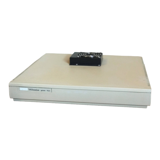
VAXstation 4000 Model 60 and VLC
Condensed Service Information
Order Number: EK-V466H-PS. A01
August 1992
This manual is a condensed version of the VAXstation 4000 Model 60
Service Information and VAXstation 4000 VLC Service Information guides.
The information in this manual supersedes the information in the original
Model 60 and VLC service guides.
Revision/Update Information:
This is a new manual.
Digital Equipment Corporation
Maynard, Massachusetts
Advertisement
Table of Contents

Related Manuals for Digital Equipment VAXstation 4000/60


Summary of Contents for Digital Equipment VAXstation 4000/60
- Page 1 This manual is a condensed version of the VAXstation 4000 Model 60 Service Information and VAXstation 4000 VLC Service Information guides. The information in this manual supersedes the information in the original Model 60 and VLC service guides. Revision/Update Information: This is a new manual. Digital Equipment Corporation Maynard, Massachusetts...
- Page 2 Software clause at DFARS 252.227-7013. © Digital Equipment Corporation 1992. All Rights Reserved. The following are trademarks of Digital Equipment Corporation: DEC, DECstation, Digital, KA46, KA48, MS44-AA, MS44L-AL, MS44-CA, RRD42, RX26, RZ, TURBOchannel, ThinWire, VAXELN, VAXstation, VAXstation 4000 VLC, VMS, and the DIGITAL logo.
-
Page 3: Table Of Contents
Contents About This Guide ..........xiii 1 System Configuration VAXstation 4000 Model 60/VLC System Box Overview . - Page 4 2.8.7 Interval Timer Self-Test (T 7) ......2–17 2.8.8 System Self-Test (T 8) ......2–18 Network Interconnect Self-Test (T 9) .
- Page 5 3.1.2.6 DIAGENV ........3–5 3.1.2.7 ERROR .
- Page 6 VLC FRU Removal/Replacement Hints ....4–14 4.5.1 VLC FRU Locations ....... . 4–15 Hard Disk Drive .
- Page 7 A.2.22 SPXg and SPXgt Graphics Self-Test Extended Summary Screen (Model 60 Only) ......A–64 Graphics Utilities .
- Page 8 D FRU Part Numbers Precautions ......... D–2 Model 60 System Box FRUs .
- Page 9 Figures 2–1 Successful System Test ......2–25 2–2 Unsuccessful System Test ......2–26 2–3 Summary Screen .
- Page 10 2–11 System Self-Test (8) ....... . 2–18 Network Interconnect Self-Test (9) ..... 2–12 2–19 2–13...
- Page 11 A–22 Graphics Self-Test Error Codes ..... . . A–55 Color Compare Failures - One Head ....A–23 A–61 A–24...
- Page 12 D–12 SZ03 Expansion Box FRUs ......D–11 SZ03 Expansion Box FRUs - Miscellaneous Hardware ..D–13 D–12 D–14...
-
Page 13: About This Guide
VAXstation 4000 Model 60 and VLC systems. In addition, it is for customers who have a self-maintenance agreement with Digital Equipment Corporation. This is a condensed version of the VAXstation 4000 Model 60 and VLC service guides. - Page 14 • Appendix C, ‘‘Troubleshooting,’’ contains troubleshooting tables that list symptoms, possible causes, and corrective actions. • Appendix D, ‘‘FRU Part Numbers,’’ contains tables that provide part numbers for field-replaceable units (FRUs). Associated Documentation The following documents provide additional information about the VAXstation 4000 Model 60 and VLC systems: Document Title Part Number...
- Page 15 Conventions This guide uses the following conventions: Convention Description Warning Contains important information about personal safety. Caution Contains information to prevent damage to the equipment. Note Contains general information. Part number. UPPERCASE Commands are shown in UPPERCASE to separate them from text. indicates that you hold down the Ctrl key while you press Ctrl x Ctrl x...
-
Page 17: System Configuration
System Configuration This chapter describes the components, cabling, and specifications of the VAXstation 4000 Model 60 and VAXstation 4000 VLC system boxes. The following topics are included in this chapter: Section 1.1 VAXstation 4000 Model 60/VLC System Box Overview Section 1.2 Monitor and Graphics Modules Section 1.3 Power Supply... -
Page 18: Vaxstation 4000 Model 60/Vlc System Box Overview
1.1 VAXstation 4000 Model 60/VLC System Box Overview Table 1–1 contains a comparison of the components located in the VAXstation 4000 Model 60 and VLC system boxes. The graphics/audio components are compared in a separate table, Table 1–3. Table 1–1 VAXstation 4000 Model 60/VLC System Box Configuration Comparison Component VAXstation 4000 Model 60 VAXstation 4000 VLC... -
Page 19: Monitor And Graphics Modules
1.2 Monitor and Graphics Modules Table 1–2 lists monitors supported by the Model 60 and VLC systems. Table 1–3 provides a detailed graphics module/monitor cross reference. Table 1–2 Monitor Cross Reference for VAXstation 4000 Model 60 and VLC Monitors Resolution and Refresh Rate Color Support VRT13-DA,D3 1024x768 @ 60 Hz... -
Page 20: Vaxstation 4000 Model 60 And Vlc Graphic Module/Monitor Cross Reference
Table 1–3 is a cross reference of the monitors supported by the Model 60 LCG modules and the monitors supported by the VLC frame buffers. Table 1–3 VAXstation 4000 Model 60 and VLC Graphic Module/Monitor Cross Reference Module Part Number Module ID Module Resolution and... - Page 21 Table 1–3 (Cont.) VAXstation 4000 Model 60 and VLC Graphic Module/Monitor Cross Reference Module Part Number Module ID Module Resolution and Description Connector Refresh Rate Monitor Support VAXstation 4000 Model 60 54-20770-01 3-coax D-sub 1280x1024 VRT16-DA,D4,HA,H4 PV21X-GA (4 connectors) @ 66 Hz VR320-CA,C4 8-Plane high res quad VRT19-DA,D3,D4,HA,H4...
- Page 22 Table 1–3 (Cont.) VAXstation 4000 Model 60 and VLC Graphic Module/Monitor Cross Reference Module Part Number Module ID Module Resolution and Description Connector Refresh Rate Monitor Support VAXstation 4000 VLC 54-20774-01 15-pin D-sub 1024x768 VRT13-DA,D4 PV31G-AB @ 60 Hz VRC16-CA,C4 (unsupported) Graphics/audio frame buffer module 2 54-20776-01...
-
Page 23: Power Supply
Table 1–4 lists the SHOW CONFIG displays for each LCG and frame buffer module. Table 1–4 LCG/Frame Buffer SHOW CONFIG Quick Reference LCG/Frame Buffer Module SHOW CONFIG Display Model --> HR - 8 PLN FB - V x.x PV21X-GD 8-Plane high res color LCG -->... -
Page 24: Vaxstation 4000 Model 60/Vlc Power Supply Specifications
Table 1–5 (Cont.) VAXstation 4000 Model 60/VLC Voltage Comparison Power Supply VAXstation 4000 Model 60 VAXstation 4000 VLC Wattage 251 W 106 W Voltages Volts dc Ampere Volts dc Ampere +5.1 19.52 +5.1 10.0 +3.3 6.39 +3.3 1.98 +12.1 3.82 +12.1 -12.0 0.69... - Page 25 Parameter (Output Characteristics) Specifications Minimum Typical Maximum +5.1 V reg. 4.90 V 5.05 V 5.20 V short term +5.1 V reg. +4.85 V +5.10 V +5.25 V long term +12.1 V reg. +11.70 V +12.10 V +12.50 V short term +12.1 V reg.
-
Page 26: Internal Cabling
1.4 Internal Cabling Table 1–7 compares the VAXstation 4000 Model 60 and VLC internal system devices and their cables. Table 1–7 Internal System Devices and Their Cables Comparison System Device /Cable VAXstation 4000 Model 60 VAXstation 4000 VLC SCSI devices Three drives (2 fixed and 1 One fixed drive removable) -
Page 27: Vaxstation 4000 Model 60/Vlc Control Panel
Table 1–9 contains a list and description of the VAXstation 4000 Model 60 and VLC system box controls and indicators. Unless noted, the controls apply to both models. Table 1–9 VAXstation 4000 Model 60/VLC Control Panel Control/Indicator Description AC power switch Controls ac power to power supply Does not affect power outlet provided for add-on peripherals Power OK LED... -
Page 28: I/O Connectors
1.6 I/O Connectors The I/O panel provides connectors to devices that are external to the system. The system configuration determines which external devices are connected to the panel. Table 1–10 lists the I/O connectors that are found on the VAXstation 4000 Model 60 and VLC systems. -
Page 29: Diagnostic Testing
Diagnostic Testing This chapter provides the diagnostic testing information and test commands that are used with the VAXstation 4000 Model 60 and VLC systems. It includes procedures for setting up the diagnostic environments, running the self-tests, and invoking utilities. In addition, this chapter describes the system tests that run only on the Model 60. -
Page 30: Diagnostic Functions
2.1 Diagnostic Functions The VAXstation 4000 Model 60 and VLC system firmware provides the diagnostic functions listed in Table 2–1. Table 2–1 Diagnostic Functions Function Description Power-up test Tests and initializes all devices Extended self-test Tests devices in the system sequentially with the TEST command System test Tests all devices in the system interactively... -
Page 31: Successful Power-Up And The Halt Command
2.2.1 Successful Power-Up and the HALT Command The following table explains the system’s response to the three HALT commands during a successful power-up. If the power-up is successful and the HALT parameter is set to... Then the system... Tries to restart the operating system. (The system continuously reboots after each restart failure.) Tries to boot the default boot device. -
Page 32: Displaying System Configuration
2.3 Displaying System Configuration The VAXstation 4000 Model 60 and VLC firmware provides two configuration commands, SHOW DEVICE and SHOW CONFIG. Use this command... To determine the... SHOW DEVICE Information on mass storage devices included in the system SHOW CONFIG Overall system configuration 2.3.1 SHOW DEVICE Command To determine the presence of storage devices such as a hard disk, diskette... -
Page 33: Show Config Command
The following table provides a description of each column shown in Example 2–1: Column Name Description VMS/VMB Is the operating system’s interpretation of what the device is. For example, with a VMS operating system, a fixed drive is interpreted as a DKA300. ADDR Lists the Ethernet hardware address or SCSI device ID. -
Page 34: Configuration Table
Example 2–2 Configuration Table KA46-A BL3-186-V1.0 ! System type and firmware revision * 08-00-2B-F3-31-03 ! Ethernet hardware address 16 MB ! Total memory DEVNBR DEVNAM INFO ------ ------ ---- ! Non-volatile RAM ! 2D high res. color graphics rev 2.7 HR - 8 PLN FB -2.7 ! Serial line controller CACHE OK... -
Page 35: Displaying Error Information
2.4 Displaying Error Information The following table describes how to determine if a device is failing: If you need to determine whether an error occurred on... Then enter the... Any device SHOW ERROR command A specific device SHOW ERROR command followed by the device number Example 2–3 shows the results of the SHOW ERROR command when an error is present. -
Page 36: Setting Up The Diagnostic Environment
2.5 Setting Up the Diagnostic Environment Before you run a self-test, you must do the following: Step Action Comment Put the system in console mode. Shut down the operating system or power up the system if you do not have the console prompt. -
Page 37: Set Diagenv Commands
To set the diagnostic environment, enter one of the console commands listed in Table 2–2. Table 2–2 SET DIAGENV Commands Command Result SET DIAGENV 1 Sets environment to customer environment. SET DIAGENV 2 Sets environment to Digital Services environment. SET DIAGENV 3 Sets environment to manufacturing environment. -
Page 38: Device Tests
2.6 Device Tests Table 2–3 lists the device tests and corresponding mnemonics, decimal ID, binary ID, and loopback requirements for the VAXstation 4000 Model 60 and VLC systems. The synchronous communications device test (ID 12) and the TURBOchannel adapter device test (ID 13) apply only to the Model 60. Table 2–3 Device Test IDs and Mnemonics Decimal Loopback Required,... -
Page 39: Running Self-Tests
2.7 Running Self-Tests This section describes the test command interface and syntax rules used to run the self-test on a device. Note Refer to Table 2–3 for a complete list of device test IDs and mnemonics. 2.7.1 Device Test Syntax Rules The following sections describe the correct syntax required to run device self-tests. -
Page 40: Descriptions Of Self-Tests
2.8 Descriptions of Self-Tests This section describes the VAXstation 4000 Model 60 and VLC self-tests that are listed in Table 2–3. Note The self-tests are arranged numerically by decimal ID. Each section title contains the self-test name and decimal ID. Some sections contain Setup Notes which contain information that you should know before you run the tests. -
Page 41: Graphics Self-Test (T 2)
2.8.2 Graphics Self-Test (T 2) Note In this section, ‘‘graphics’’ refers to all the graphics modules used by the VAXstation 4000 Model 60 and VLC systems. Use T 2 for the graphics self-test. Both the SHOW CONFIG and SHOW ERROR commands will display the specific graphics module mnemonic. -
Page 42: Dz Self-Test (T 3)
Table 2–5 lists the tests that are included in the graphics self-test. Table 2–5 Graphics Self-Test (2) Self-Test Function Video test Tests the VRAM cache memory and the communication between the S-chip and VRAM. Initializes the Brooktree and sets up the video screen. Sets up the video registers in the S-chip. -
Page 43: Dz Self-Test
Table 2–6 lists the tests that are included in the DZ self-test. Table 2–6 DZ Self-Test (3) Self-Test Function Reset test Resets the DZ chip and sets up its lines to their default values. An error occurs if the device does not reset or if the line parameters do not get set up properly. -
Page 44: Cache Self-Test (T 4)
2.8.4 Cache Self-Test (T 4) Table 2–7 lists the tests that are included in the cache self-test. Table 2–7 Cache Self-Test (4) Self-Test Function Data store test Tests the data store in the primary cache. A two pass memory test is performed on the data store. This test performs a read/compare/complement/write in both the forward and reverse directions. -
Page 45: Floating-Point Unit Self-Test (T 6)
Table 2–8 (Cont.) Memory Self-Test (5) Self-Test Function Memory test Performs a read/compare/complement/write on the memory in the (forward) forward direction. If a page is found to be bad, the appropriate bit in the memory bitmap is cleared. Memory test Starts at the last address to be tested and performs a (reverse) read/compare/complement/write on memory. -
Page 46: System Self-Test (T 8)
Table 2–10 Interval Timer Self-Test (7) Self-Test Function Interrupt test Enables the interval timer interrupts. It lowers the IPL for 30 ms and counts the number of interrupts. An error occurs if there are too few or too many interrupts. Refer to Section A.2.4 for a list of interval timer (IT) test error codes. -
Page 47: Network Interconnect Self-Test
Table 2–12 lists the tests that are included in the Network Interconnect (NI) self-test. Table 2–12 Network Interconnect Self-Test (9) Self-Test Function Network Verifies the 32-byte network address ROM which contains the Address ROM unique 6-byte network address along with the 2-byte checksum and test test data byte. -
Page 48: Scsi Self-Test (T 10)
2.8.10 SCSI Self-Test (T 10) Setup Notes: • Removable media drive devices will fail in extended mode if media is not installed. • If some or all devices do not show up in the configuration display after running the test, check that: All devices have a unique ID number. -
Page 49: Audio Self-Test (T 11)
2.8.11 Audio Self-Test (T 11) The function of the audio self-test is to test the system’s ability to send a beep code to the speaker. The following table lists the location of all audio functionality for the VAXstation 4000 Model 60 and VLC systems: VAXstation 4000 Model Audio Functionality Location Model 60... -
Page 50: Turbochannel Adapter Self-Test (T 13) (Model 60 Only)
2.8.13 TURBOchannel Adapter Self-Test (T 13) (Model 60 Only) Restriction The system power-up self-test run time restricts the self-test’s ability to call the emulator to run power-up self-tests on the option firmware. To Initialize the TURBOchannel and Option Arbitrary TURBOchannel resets are not performed. The following explains the process to initialize the TURBOchannel and option: If you halt VMS and want to run the emulator, but do not want to maintain the state of the TURBOchannel or the option, enter the UNJAM command... -
Page 51: Setting Up System Test Environments (Model 60 Only)
Table 2–15 (Cont.) TURBOchannel Adapter Self-Test (13) Self-Test Function TCA FIFO test Loads up the TCA FIFO at longwords with an increasing value, starting at 1 and ending with 512. The FIFO is then emptied and the count is checked against the read values from the FIFO. An error is reported if: •... -
Page 52: System Test Monitor (Model 60 Only)
Important Notes About the System Test The following are important notes about the system test: • The system test runs under a modified VAXELN kernel which is loaded from ROM. • The system test causes a worst-case environment in terms of system interaction, using maximum DMA and interrupts. -
Page 53: Display From The System Test
2.10.1 Display from the System Test Figure 2–1 shows the output from a successful system test. Figure 2–1 Successful System Test KA46-A V1.0 00 00:02:00.03 2 LCG 3 DZ 4 MEM 9 NI 10 SCSI 11 AUD 12 COMM LJ-00633-TI0 The following table describes the fields in Figure 2–1. -
Page 54: Unsuccessful System Test
Figure 2–2 shows the display when the system test is unsuccessful. Figure 2–2 Unsuccessful System Test KA46-A V1.0 00 00:02:00.03 2 LCG 3 DZ 4 MEM 9 NI 10 SCSI 000101 000125 00 00:01:56:01 11 AUD 12 COMM LJ-00119-TI0 If the Device Fails If the device fails, then the device status line becomes the error message. -
Page 55: Descriptions Of System Tests
2.11 Descriptions of System Tests You can get summary information about the most recent system test using either of the two methods described in the following table: Method Description Interrupt system test by pressing Stops the system test and displays summary screens for the devices. -
Page 56: Dz System Test (Model 60 Only)
Figure 2–3 Summary Screen 10 SCSI 000101 000125 00 00:01:56:01 targ devnam wrts snddia sfterr RZ24 RZ56 RRD42 Ext_err 00000045 00301004 45670000 00004543 08003589 98001234 LJ-00120-TI0 2.11.1 DZ System Test (Model 60 Only) Note Be sure that loopback connectors are installed when the system is in the Digital Services environment. -
Page 57: Dz System Test Error
Mode Description Burst Performs in the same way as functional mode except the lines are tested with the following specifications: Baud rate - 19.2K Character width - 8-bit Parity - odd The following is an example of the DZ system test error. Example 2–5 DZ System Test Error ?? 001 3 DZ 0220 This error code means that not all characters were received on line 1 and... -
Page 58: Network Interconnect System Test (Model 60 Only)
2.11.2 Network Interconnect System Test (Model 60 Only) Setup Notes: • The selected NI port must be connected to a network, or have a loopback installed. • Maximum testing of hardware occurs on a live network with MOP enabled. The network system test tests the network port using external loopback packets. -
Page 59: Scsi System Test
Table 2–17 lists the tests that are in the SCSI system test. Table 2–17 SCSI System Test Self-Test Function Inquiries test Performs inquiries to find out which devices are connected to the SCSI bus. Size bus test Spins up all the hard disk drives, makes sure the drives are ready (if not in customer environment), forces disk block sizes to 600 bytes, and obtains the capacity of the drives. -
Page 60: Dsw21 Synchronous Communication System Test
Example 2–7 shows a SCSI system test summary display. Example 2–7 System Test Summary Display ADR RDS WRTS FRU CMD PHS INF LBNSTRT XFERSIZ --- --- ---- --- --- --- --- ------- ------- 1/0 10987 3/0 5643 5643 1378 4/0 28 150 28 ------------------------------------------------------------ 4/0 XX XX XX XX XX XX XX XX XX XX XX XX XX XX XX XX XX XX XX... -
Page 61: Utilities
Example 2–8 shows the DSW21 synchronous communication system test summary. Example 2–8 Communication System Test Summary COMM Test Summary Screen.......... ------------------------------------------------------------------ SCC1 Tx: 36 Rx: 36 Err: 0 INT-NOCABLE SCC2 Tx: 36 Rx: 36 Err: 0 EXT-H3199 SCC3 Tx: 36 Rx: 36 Err: 0 INT-NOCABLE Status Block:... -
Page 62: Utility Test Format
2.12.2 Utility Test Format Following is the format for a utility test that runs completely from the command line: >>> T [EST]/UT[ility] {dev_nbr} {util_nbr} {opt_p1,...,opt_pn} The following table describes the utility test format: Code Description dev_nbr Number of the device on which you want to run the utility. util_nbr Number of the utility you want to run. -
Page 63: Utilities List Command Procedures
Figure 2–4 Utilities List >>> T/UT 2 0 - LCG-wh-scrn 1 - LCG-rd-scrn 2 - LCG-bl-scrn 3 - LCG-gn-scrn 4 - LCG-4c-cbar 5 - LCG-8c-cbar 6 - LCG-8g-gscl 7 - LCG-ee-scrn 8 - LCG-ci-xhct 9 - LCG-sc-hhhs LCG_util>>> 8 LJ-00117-TI0 2.12.4 Utilities List Command Procedures The following section describes several utilities list command procedures: To Exit the Utility... -
Page 64: Graphics Utilities
2.12.5 Graphics Utilities The graphics utilities provide ten screens of color bars and geometric programs. Refer to Example 2–9 for a description of the ten screen utilities. The graphics utilities apply to the LCG, SPXg, SPXgt, and graphics/audio frame buffer graphics modules. -
Page 65: Ni Listener
Utility Function Description SET MOP Enable/disable NI listener SHOW MOP NI listener state SET TRIGGER Enable/disable EBM SHOW TRIGGER EBM state 2.12.6.1 NI Listener The NI listener has the following characteristics: • The NI listener can send and receive messages while the system is in console mode. -
Page 66: Scsi Utilities
2.12.7 SCSI Utilities The following table describes the SCSI utilities: Utility Description Floppy Key utility This utility is used in Digital Services environment. The key utility writes a key on block 0 of the floppy media. The key is used by the system test in Digital Services environment. -
Page 67: Invoking Scsi Utilities
2.12.8 Invoking SCSI Utilities Note Use the SHOW DEVICE command to display information about the Ethernet controller and the SCSI drives that are attached to the system. For more information about the SHOW DEVICE command, see Section 2.3.1. To invoke the SCSI utilities, perform the following steps: Step Action Result Enter the TEST/UTIL SCSI... -
Page 68: Scsi Utility Menu
Refer to Example 2–10 for a sample SCSI utilities session. 2.12.9 SCSI Utility Menu Example 2–10 shows a sample SCSI utilities session. Example 2–10 SCSI Utilities Sample Session >>> T/UT 10 ! Type in this command (or T/UT SCSI) 1 - SCSI-flp_key ! Floppy key utility. -
Page 69: Scsi Utilities Display
Figure 2–5 shows a SCSI utilities display. Figure 2–5 SCSI Utilities Display >>> T/UT 10 1 - SCSI-flp_key 2 - SCSI-tp_key 3 - SCSI-hd_dsk_eras 4 - SCSI-flp_fmt SCSI_util>>> LJ-01469-TI0 Diagnostic Testing 2–41... -
Page 70: Scsi Utility Guidelines
2.12.10 SCSI Utility Guidelines Follow these guidelines about the SCSI utilities: • The key utilities can only be run from the Digital Services environment. An error code of 181 displays if you run the key utilities from the customer environment. •... -
Page 71: Mips/Rex Emulator
2.12.11.1 MIPS/REX Emulator Invoking the Emulator Enter the following command to invoke the emulator: >>> T/UT TCA The system will respond with the following message: **KA46/49 TURBOCHANNEL REX EMULATOR** >> Available Option Script Functions Enter the following command to see a list of available script functions: T TCO LS Example: >>T TC0 LS... - Page 72 Example: >>T TCO/? flash eprom sram rmap phycsr nirom intlpbk iplsaf pmccsr pktmem >> Invoking Option Self-Test Enter the following command to invoke an individual self-test: Syntax: >> T TC0/[Self-Test Name] Example: >> T TC0/FLASH A successful test will return you to the prompt. Option Error Message Example The following is an example of an emulator self-test error message: >>...
- Page 73 Exiting the Emulator Press Ctrl/D to exit the emulator and then access the system console prompt. Example: (CTRL/D will not be echoed) >> >>> Refer to Section A.2.16 for additional REX commands that are supported by the MIPS/REX Emulator. Diagnostic Testing 2–45...
-
Page 75: Using The Console
Using the Console This chapter describes the system console commands and discusses how to use alternate consoles with the VAXstation 4000 Model 60 and VLC systems. Diagnostic commands, used to troubleshoot a system, are described in Chapter 2. The following topics are included in this chapter: Section 3.1 System Console Section 3.1.1... -
Page 76: System Console
3.1 System Console Standard console commands for the VAXstation 4000 Model 60 and VLC systems are listed by functional groups as follows: Functional Group Description or Example Additional commands HELP or ?, LOGIN, and REPEAT commands SET/SHOW commands Used to set or examine system parameters and configuration Memory commands DEPOSIT, FIND, and EXAMINE commands... -
Page 77: Set And Show Commands
3.1.2 SET and SHOW Commands The VAXstation 4000 Model 60 and VLC SET and SHOW commands are used to set and examine system parameters. Table 3–1 provides a description of the parameters for the SET and SHOW commands. Table 3–1 SET/SHOW Parameters Parameter Meaning SHOW... -
Page 78: Set And Show Command Syntax
3.1.2.1 SET and SHOW Command Syntax The following table shows the syntax and examples of the SET and SHOW parameters: Syntax Example SHOW parameter SHOW BOOT SET parameter value SET BOOT DKA200: 3.1.2.2 BFLG The BFLG parameter is the default bootflag. It is equivalent to R5:xxxxxxxx in the boot command. -
Page 79: Config
3.1.2.4 CONFIG The CONFIG parameter is used to display the system configuration and device status. • The SET command does not apply to this parameter. • Use SHOW DEVICE for more information on SCSI devices. Refer to Section 2.3.2 for an example of a configuration display. 3.1.2.5 DEVICE The DEVICE parameter is used to display SCSI and Ethernet device information. -
Page 80: Error
To set the diagnostic environment, enter a console command from Table 3–3. Table 3–3 SET DIAGENV Command Command Result SET DIAGENV 1 Sets environment to customer environment SET DIAGENV 2 Sets environment to Digital Services environment SET DIAGENV 3 Sets environment to manufacturing environment SET DIAGENV 80000001 Sets environment to loop on error in Digital Services environment... -
Page 81: Estat
3.1.2.8 ESTAT The ESTAT parameter displays status information about the system test. The SET command does not apply. The following is an example of the SHOW ESTAT command: Command Result SHOW ESTAT Displays the summary from the most recent system test since power-up. -
Page 82: Halt
Command Result SHOW FBOOT FBOOT = 1 3.1.2.11 HALT The HALT parameter determines the recovery action that the system takes after power-up, system crash, or halt. The following table defines the HALT parameter values: Value Definition System tries to restart operating system. If restart fails, then the system tries to reboot. -
Page 83: Mem
Example: >>> SET KBD 0) Dansk 8) Francais (Suisse Romande) 1) Deutsch 9) Italiano 2) Deutsch (Schweiz) 10) Nederlands 3) English 11) Norsk 4) English (British/Irish) 12) Portugues 5) Espanol 13) Suomi 6) Francais 14) Svenska 7) Francais (Canadian) 15) Vlaams 3 >>>... -
Page 84: Pse And Pswd
3.1.2.15 PSE and PSWD The PSE parameter is the enable console password bit. When enabled, the console password is required to access the console. The PSWD parameter is used to set the console password. The SHOW command does not apply. The following are key points to remember about passwords: If the PSE is equal to... -
Page 85: Scsi
How to Log In Follow these procedures to log in: Step Procedure Set PSE to 1. Enter the LOGIN command at the >>> prompt. Enter the password at the PSWD0>>> prompt. The password must be exactly 16 characters. Valid password characters are 0 through 9 and A through F. 3.1.2.16 SCSI The SCSI parameter sets the SCSI ID for the system SCSI controller. -
Page 86: Memory Commands
3.1.3 Memory Commands The following table describes three memory commands that manipulate memory and registers: Command Function DEPOSIT Enters values into memory locations or registers EXAMINE Displays the contents of memory locations or registers FIND Finds a good section of memory or restarts parameter block 3.1.3.1 DEPOSIT Command The DEPOSIT command is used to write to memory locations from the console. -
Page 87: Deposit Command Qualifiers
Table 3–4 DEPOSIT Command Qualifiers Qualifier Description Data Size Byte (8 bits) Word (16 bits) Longword (32 bits) Quadword (64 bits) Address Space Virtual memory Physical memory Internal processor register General purpose register Machine register Range of Addresses /N:X Specifies that the X+1 locations be written with the value specified by DATA Protection Unprotects a protected memory location. -
Page 88: Examine Command
3.1.3.2 EXAMINE Command The EXAMINE command is used to display the contents of specific memory locations from the console. Syntax: EXAMINE /[qualifier] [address] Table 3–5 lists the qualifiers and what each one specifies. Table 3–5 EXAMINE Command Qualifiers Qualifier Description Data Size Byte (8 bits) Word (16 bits) -
Page 89: Find Command
The following example of the EXAMINE command reads the Ethernet hardware address: >>> EXAMINE/P/N:5 20090000 P 20090000 0000FF08 P 20090004 0000FF00 P 20090008 0000FF2B P 2009000C 0000FF1B P 20090010 0000FF48 P 20090014 0000FFE3 3.1.3.3 FIND Command Use the FIND command to search memory for either of the following: •... -
Page 90: Processor Control Commands
3.1.4 Processor Control Commands The following table lists the processor control commands: Command Function BOOT Bootstraps the operating system CONTINUE Starts the CPU running at the current program counter (PC) HALT Stops the CPU INITIALIZE Initializes processor registers START Starts the CPU at a given address UNJAM Sets devices to an initial state 3.1.4.1 BOOT Command... -
Page 91: Continue Command
The following example shows the system performing a conversational boot from DKA200. If the system cannot boot from DKA200, it tries a conversational boot from DKA400. Example: >>> BOOT /R5:00000001 DKA200, DKA400 3.1.4.2 CONTINUE Command The CONTINUE command switches the system from console mode to program mode. -
Page 92: Alternate Consoles
3.2 Alternate Consoles The VAXstation 4000 Model 60 and VLC systems provide two ways to use alternate consoles if the graphics subsystem fails. Console commands may be entered on a terminal connected to the printer port of the workstation or from a network connection to the Ethernet port. - Page 93 Follow these procedures to access the console from the network: Step Procedure Identify the Model 60 or VLC hardware Ethernet address. Verify that there is a VMS operating system on the same Ethernet segment as the Model 60 or VLC (the systems cannot be separated by a bridge or router). Set the following VAXstation 4000 computer parameters: •...
-
Page 94: Network Console Session
Example 3–1 is an example of a network console session. Example 3–1 Network Console Session $ MC NCP NCP>SHOW KNOWN CIRCUITS Known Circuit Volatile Summary as of 27-MAR-1991 13:50:02 Circuit State Loopback Adjacent Name Routing Node SVA-0 25.14 NCP>CONNECT VIA SVA-0 SERVICE PASSWORD 1111111111111111 - _ PHYSICAL ADDRESS 08-00-2B-1B-48-E3 ! Connects to the console Console connected (press CTRL/D when finished) >>>... -
Page 95: Fru Removal And Replacement Hints
FRU Removal and Replacement Hints The following section contains VAXstation 4000 Model 60 and VLC FRU removal and replacement hints. Refer to the VAXstation 4000 Model 60 Service Information and VAXstation 4000 VLC Service Information guides for complete FRU removal and replacement procedures, illustrations, and part numbers. The following topics are included in this chapter: Section 4.1 Precautions... -
Page 96: Precautions
4.1 Precautions Only qualified service personnel should remove or install FRUs. Note It is the customer’s responsibility to back up the software before Digital Services personnel arrive at the site. This is important to ensure that data is not lost during the service process. The customer should also shut down the workstation software. -
Page 97: System Preparation
Step Procedure Use the SHOW CONFIG command and write down the following information: • System ROM version • Graphics type • Memory configuration • SCSI devices and IDs Make sure this configuration agrees with the actual hardware. If the configuration does not agree, make sure the following are true: •... - Page 98 Step Procedure Use the SHOW CONFIG command to determine the presence of devices, test status, and quantity of memory inside the system. • Record the current system configuration information for reference. • After adding the new device or module: Compare the new configuration with the previous one to help verify that all devices are present and functioning correctly.
-
Page 99: Model 60 Fru Removal/Replacement Hints
4.4 Model 60 FRU Removal/Replacement Hints The following section contains Model 60 FRU removal and replacement hints. 4.4.1 Model 60 FRU Locations Figure 4–1 shows the location of the Model 60 system FRUs. Figure 4–1 System FRU Locations (Front View) FRU Removal and Replacement Hints 4–5... -
Page 100: Hard Disk Drive
4.4.2 Hard Disk Drive The following hints provide removal and replacement assistance: Hint Procedure Bracket/Disk Removal Pull the colored tab on the drive bracket toward the front of the system. The tab is located at the upper left corner of the bracket. Lift the drive and bracket from the system box. -
Page 101: Rx26 Diskette Drive
4.4.3 RX26 Diskette Drive The following hints provide removal assistance: Hint Procedure Bracket/Diskette Removal Pull the tab on the drive bracket toward the power supply of the system. The tab is located at the upper front right corner of bracket. Push the tab behind the screw hole at the bottom center of the bracket to the right. -
Page 102: Power Supply
4.4.5 Power Supply The following hints provide removal and replacement assistance: Warning Do not attempt to open the power supply. There are dangerous voltages inside; there are no user-serviceable parts. Hint Procedure Removal Remove the hard disk drive. Pull forward on the blue tab (on the right toward the front of the box) just under the supply and lift the front of the supply slightly. -
Page 103: Lights And Switches Module
4.4.6 Lights and Switches Module The following hints provide removal assistance: Hint Procedure Removal Remove the hard disk drive bracket. Remove the removable media drive bracket. Disconnect the module connector from the system module by lifting up on the module where it overlaps the system module. Lift the module away from the front of the system. -
Page 104: Lcg Graphics Module
4.4.8 LCG Graphics Module Caution Wear an antistatic wrist strap and place an antistatic mat under the system when removing and replacing any modules. Hint Procedure Removal Pull the two tabs above the module towards the front of the system. Rotate the front of the module up. -
Page 105: Scanproc Graphics Module
4.4.9 ScanProc Graphics Module The following hints provide removal and replacement assistance: Hint Procedure SPXg Removal Remove the frame buffer/graphics subsystem processor (GSP) assembly. SPXg Replacement If the new FRU is a SIMM memory module, install it on the frame buffer module. - Page 106 Hint Procedure SPXgt Removal Remove the plastic clip that holds the GSP module to the frame buffer module. Note: Attempting to remove both the GSP module and the frame buffer module, by grasping the frame buffer module tail, could result in damage to the module.
-
Page 107: System Module (Cpu)
4.4.10 System Module (CPU) The following hints provide removal and replacement assistance: Hint Procedure Removal Remove the system module (CPU) by lifting the front slightly, so that it clears the two guides at the front right and left of the module. Use the large center connector and pull the module toward the front of the system box. -
Page 108: Turbochannel Adapter And Option Modules
4.4.12 TURBOchannel Adapter and Option Modules The following hints provide removal and replacement assistance: Hint Procedure TURBOchannel Adapter/Option Removal Disconnect the TURBOchannel option cable. Remove the two screws that hold the option plate over the outside of the TURBOchannel option. Disconnect and remove the SCSI cable from system board and from the opening over the external TURBOchannel port. -
Page 109: Vlc Fru Locations
4.5.1 VLC FRU Locations Figure 4–2 shows the location of the VLC system FRUs. CPU module (PN 54-20768-01) Power supply (PN H7109-AA) RZ23L 121 MB disk drive (PN RZ23L-E), or RZ24L 245 MB disk drive (PN RZ24L-E) Memory modules (PN 20-36453-05; in Europe, order PN 54-21231-AA) Graphics/audio frame buffer modules Figure 4–2 System FRU Locations (Rear View) 3 8 %... -
Page 110: Hard Disk Drive
4.5.2 Hard Disk Drive The following hints provide removal and replacement assistance: Hint Procedure Removal Depress the cricket clip on the side of the drive and slide the drive towards the power supply until the metal screws (on the bottom of the drive) are aligned with the mounting holes on the skid plate. -
Page 111: Graphics/Audio Frame Buffer Module
Caution Wear an antistatic wrist strap and place an antistatic mat under the system when removing and replacing any modules. 4.5.4 Graphics/Audio Frame Buffer Module The following hints provide removal assistance: Hint Procedure Removal Remove the two mounting screws. Lift the module up and to the front until the video jack clears the plastic system box enclosure. -
Page 112: Ms40 Memory Module
4.5.6 MS40 Memory Module Caution You can easily damage memory components with static electricity. Wear an antistatic wrist strap when you install or remove memory components. The following hints provide removal assistance: Hint Procedure Removal If you replace a module in the back of the system board, you must remove the modules at the front first, and work towards the back. -
Page 113: A Interpreting Error Codes
Interpreting Error Codes The VAXstation 4000 Model 60 and VLC system firmware always tries to report any detected hardware errors to the console device and to the LEDs. The Model 60 LEDs are located on the front of the system box and the VLC LEDs are located on the rear of the system box. -
Page 114: Error Messages Overview
A.1 Error Messages Overview The console reports the following two types of errors: Error Type Description Immediate These errors are displayed immediately after running a test, without additional user intervention. Extended These errors display more error information in a different format. -
Page 115: Fru Codes
The extended error display has two lines: • An error line similar to the immediate error message. The error code (last field of the first line) is in hexadecimal. • A second line with up to eight longwords of error information. Extended Error Message Format The extended error messages appear in the following format: ?? 150 10 SCSI 0032... -
Page 116: Fru Codes
Table A–1 FRU Codes FRU Code System module; the mnemonic identifies the device. Keyboard Mouse Monitor 1 Monitor 2 010-019 Graphics modules 020-029 COMM options (Model 60 only) 030-039 BUS adapters (Model 60 only) Memory Module Codes 040-045 FRU Code Module Location Model 60 SCSI Drive Codes 100-170... -
Page 117: Error Codes: Self-Tests, Systems Tests, And Utilities
A.2 Error Codes: Self-Tests, Systems Tests, and Utilities The following tables describe the self-tests, system tests, and utilities for the Model 60 and VLC systems. Notes • The following tables apply to both the Model 60 and VLC systems, unless specified otherwise. •... -
Page 118: Dz Self-Test Error Codes
Table A–2 (Cont.) TOY/NVR Test Error Codes Error Decimal Hexadecimal Meaning Battery check, VRT, and NVR test have failed Update in progress has failed to clear; hard error Update in progress has failed to clear; soft error Update in progress has failed and VRT bit failure A.2.2 DZ Self-Test Error Codes The DZ self-test produces the error messages in the following table: Table A–3 DZ Self-Test Error Codes... - Page 119 Extended Error Format: This extended error message is returned by the DZ read LPR test or if a character comparison error occurs in the other DZ tests. The second field (4-digit field) is the extended error format. 001 000a ssssssss cccccccc lprlprlp llllllll rrrrrrrr eeeeeeee Where: •...
-
Page 120: Dz Suberror Codes
Table A–4 DZ Suberror Codes Suberror- Hexadecimal Meaning Read LPR Read LPR baud rate is incorrectly set Read LPR character width is incorrectly set Read LPR parity bit is incorrectly set Read LPR receiver on bit is incorrectly set DZ Modem Test DZ modem test - failed RTS or CTS loopback DZ modem test - failed DSRS or DSR &... -
Page 121: Dz System Test Error Codes (Model 60 Only
A.2.2.1 DZ System Test Error Codes (Model 60 Only) The following are error codes for the system test DZ module: ?? DZ ABCD 0 00:00:00.00 ABCD are the four DZ lines. The error codes are identical for each line. The following table identifies each line: Line Identification... -
Page 122: Memory Test Error Codes
Table A–5 Memory Test Error Codes Error Decimal Hexadecimal Meaning 16 MB memory module and a 4 MB memory module are plugged in as a pair Gap was found between memory module pairs 16 MB memory module found on a PVAX2 4 MB memory modules found after 16 MB memory modules Memory modules not plugged in as pairs... - Page 123 The memory test does not display extended error information when an error occurs. Enter the SHOW ERROR command to view the extended error information. The extended error code format is shown in the following example: Extended Error Format: xxx 4 MEM yyyy xxx 00a bbbbbbbb cccccccc dddddddd eeeeeeee Code Meaning...
-
Page 124: Interval Timer Self-Test Error Codes
Table A–6 MEM Memory Module FRU Values Module Bank Connector Model 60 Model 60 Model 60 Model 60 Model 60 Model 60 A.2.4 Interval Timer Self-Test Error Codes The interval timer test produces the error code in the following table: Table A–7 Interval Timer Test Error Codes Error Decimal... -
Page 125: System Device Self-Test Error Codes
A.2.5 System Device Self-Test Error Codes The system device self-test produces the error messages in the following table: Table A–8 System Device Self-Test Error Codes Error Decimal Hexadecimal Meaning System ROM has failed Invalidate filter RAM error ROM illegal data path value ROM checksum error ROM manufacturing check data error 1024... -
Page 126: Scsi Self-Test
Table A–9 SCSI Self-Test Error Codes Error Decimal Hexadecimal Meaning SCSI reset register test has failed SCSI configuration registers test has failed SCSI FIFO register test has failed SCSI transfer count registers test has failed SCSI Interrupt Test Failures Status registers test has failed No cause has failed High IPL, mask disabled has failed High IPL, mask enabled has failed... - Page 127 Table A–9 (Cont.) SCSI Self-Test Error Codes Error Decimal Hexadecimal Meaning SCSI Map Error Test Failures DMA mapping has failed DMA inquiry has failed Map error will not clear Map error will not set Parity error will not clear PROM function has failed SCSI PROM function has failed SCSI INIT driver has failed The SCSI test does not display extended error information when an error...
- Page 128 Extended Error Format 000B: This format is used by the register test. 001 000B aaaaaaaa bbbbbbbb cccccccc Code Meaning aaaaaaaa Error code bbbbbbbb Address of the register or location being accessed cccccccc Information about the error Extended Error Format 000C: This format is used by the interrupt test.
- Page 129 Code Meaning ffff Error code gggg Mode of operation hhhhhhhh Number of data bytes received Extended Error Format 000E: This format is used when execution of a SCSI command fails. aaa 000E bbbbcccc ddddeeee ffffgggg hhhhiiii jjjjjjjj kkkkllll mmmmmmmm Code Meaning bbbb Logical unit number...
- Page 130 Extended Error Format 000F: This format is used when the status phase returns a bad status, or when a bad sense key is seen after a request sense. aaa 000F bbbbcccc ddddeeee ffffgggg hhhhiiii jjjjjjjj kkkkkkkk Code Meaning bbbb Logical unit number cccc Device ID dddd...
- Page 131 Code Meaning hhhh Byte 14 of the request sense packet (device FRU) iiii Information about the error jjjjjjjj Number of bytes of sense data returned from the request sense kkkkkkkk Request sense key Refer to Table A–10. Extended Error Format 0011: This format is used when the data out phase sends fewer bytes than expected.
- Page 132 Extended Error Format 0012: This format is used when an unsupported message is seen. aaa 0012 bbbbcccc ddddeeee ffffgggg hhhhiiii jjjjjjjj kkkkllll mmmmmmmm Code Meaning bbbb Logical unit number cccc Device ID dddd Actual command opcode eeee Current command opcode ffff Error code gggg...
- Page 133 Code Meaning gggggggg Map register address hhhhhhhh Contents of the map register iiiiiiii Error code Extended Error Format 0014: This format is used by the data transfer test when the numbers received from two transfers are different. aaa 0014 bbbbbbbb cccccccc dddddddd Code Meaning bbbbbbbb...
-
Page 134: Scsi Information Values
The information values reported by some extended SCSI self-test errors are as follows. Refer to Table A–10 when an iiii message is displayed within the extended error format. Table A–10 SCSI Information Values Information Value Decimal Hexadecimal Meaning Valid group code bit clear in controller status register Valid group code bit set in controller status register Terminal count bit clear in controller status register... - Page 135 Table A–10 (Cont.) SCSI Information Values Information Value Decimal Hexadecimal Meaning Disconnect bit set in controller interrupt register Illegal command bit clear in controller interrupt register Illegal command bit set in controller interrupt register SCSI reset bit clear in controller interrupt register SCSI reset bit set in controller interrupt register Arbitration not won Selection timeout...
- Page 136 Table A–10 (Cont.) SCSI Information Values Information Value Decimal Hexadecimal Meaning Command phase changed too soon Data out phase changed too soon Message in phase changed too soon Message out phase changed too soon Stuck in command phase Stuck in message in phase Stuck in message out phase Stuck in data out phase Stuck in data in phase...
-
Page 137: Scsi Mode Values
Table A–10 (Cont.) SCSI Information Values Information Value Decimal Hexadecimal Meaning Out of re-tries for this command Too many bytes sent in data out phase Too many bytes sent in data in phase Reconnection timeout SCSI parity error SCSI map error The mode values reported by some extended SCSI self-test errors are as follows: Table A–11 SCSI Mode Values... -
Page 138: Scsi Utilities Messages
A.2.7 SCSI Utilities Messages The following table describes error messages returned by a SCSI utility. All Model 60 and VLC SCSI utility errors appear in the format text_message information_value. Table A–12 Text Messages for SCSI Utilities Text Meaning SCSI_E_badparam Bad parameter entered by the user SCSI_E_err Generic utility error SCSI_E_devtyp... -
Page 139: Scsi System Test Error Codes (Model 60 Only
Table A–13 Additional SCSI Information Values for Utilities Information Value Decimal Meaning Bad utility number received from the user Bad device number received from the user Bad logical unit number received from the user Device number entered by the user is the same as the controller Utility cannot be executed in this mode of operation Not enough data was returned from a SCSI command... -
Page 140: Scsi System Test Error Codes
Table A–14 SCSI System Test Error Codes Error Decimal Hexadecimal Meaning WST call failed ELN call failed Inquiry failed when sizing bus Not enough inquiry data returned when sizing Start unit failed when sizing bus Test unit ready failed when sizing bus Mode select failed when sizing bus Read capacity failed when sizing bus Mode sense failed when sizing bus... -
Page 141: Scsi System Test Summary Screen (Model 60 Only
Table A–14 (Cont.) SCSI System Test Error Codes Error Decimal Hexadecimal Meaning Wrong number bytes written in device test Data miscompare in device test Reselection timeout in device test A.2.9 SCSI System Test Summary Screen (Model 60 Only) The SCSI summary screen displays the following information: ADR RDS WRTS ERR FRU CMD PHS INF LBNSTRT XFERSIZ Code Meaning... -
Page 142: Codes (Model 60 Only)
Table A–15 DSW21 Synchronous Communication Device Self-Test Error Codes (Model 60 Only) Error Decimal Hexadecimal Meaning Self-test was unsuccessful Transmit underflow Transmitter busy Receiver busy Transmitter error Carrier detect loss Sync Comm Receive Failures Receive overflow Receive CRC error Receive abort Receive non-octet aligned Receive parity error Receive frame error... - Page 143 Table A–15 (Cont.) DSW21 Synchronous Communication Device Self-Test Error Codes (Model 60 Only) Error Decimal Hexadecimal Meaning DSW21 Comm. Device Failures Comm option test failure Comm option copy to RAM failed Comm option RAM test failed Comm option dual RAM access test Comm option interrupt test Comm option reset test Comm option internal loopback...
- Page 144 Table A–15 (Cont.) DSW21 Synchronous Communication Device Self-Test Error Codes (Model 60 Only) Error Decimal Hexadecimal Meaning DSW21 Comm. IMP Failures IMP IDMA timeout IMP SCC transmit timeout IMP SCC receive timeout IMP command timeout IMP ERR timeout IMP PB8 timeout IMP SMC2 timeout IMP SMC1 timeout (continued on next page)
- Page 145 Table A–15 (Cont.) DSW21 Synchronous Communication Device Self-Test Error Codes (Model 60 Only) Error Decimal Hexadecimal Meaning DSW21 Comm. IMP Failures IMP watchdog timeout IMP SCP timeout IMP timer 2 timeout IMP SCC3 timeout IMP PB9 timeout IMP timer 1 timeout IMP SCC2 timeout IMP IDMA timeout IMP SDMA timeout...
- Page 146 Table A–15 (Cont.) DSW21 Synchronous Communication Device Self-Test Error Codes (Model 60 Only) Error Decimal Hexadecimal Meaning DSW21 Comm. IMP Failures IMP invalid SCC channel PVAX data compare error IMP carrier detect asset timeout IMP carrier detect deassert timeout IMP CTS assert timeout IMP CTS deassert timeout IMP IDL assert timeout IMP IDL deassert timeout...
- Page 147 Table A–15 (Cont.) DSW21 Synchronous Communication Device Self-Test Error Codes (Model 60 Only) Error Decimal Hexadecimal Meaning UTIL invalid cable code DSW21 Comm. Timeout Failures Timeout comm option set response RA Timeout comm option clear command CA Timeout comm option set scheduler run SR Timeout comm option set transmit ready TR Timeout comm option set receive ready RR Comm option exception occurred...
-
Page 148: Dsw21 Synchronous Communication Device Self-Test Sequence Numbers (Model 60 Only
Table A–15 (Cont.) DSW21 Synchronous Communication Device Self-Test Error Codes (Model 60 Only) Error Decimal Hexadecimal Meaning IMP timeout waiting for host to clear SR ROM test error FBUG secure error-reserved operation Port PB3 signal stuck high Timer 3 not counting Comm option diagnostics did not complete Comm option SDMA bus error occurred Timeout waiting for IRQ assertion... - Page 149 Table A–16 (Cont.) DSW21 Synchronous Communication Self-Test Sequence Numbers (Model 60 Only) Test Number Decimal Hexadecimal Routine Description imp_op_init Option register initialization imp_br_init Base register initialization imp_cs_switch Power-up switch initialization imp_cfg Get hardware configuration imp_scr_init System control register initialization imp_core MC68302 core confidence test imp_dwcn Watchdog timer counter clear...
- Page 150 Table A–16 (Cont.) DSW21 Synchronous Communication Self-Test Sequence Numbers (Model 60 Only) Test Number Decimal Hexadecimal Routine Description imp_ilb_test SCC internal loop imp_modem_ Modem signal test test imp_elb_test SCC external loop imp_isdn_test ISDN test imp_rdb Runtime register RDB initialization imp_loc_init Runtime SCR RAM initialization imp_cable_code...
-
Page 151: Synchronous Communication Self-Test
command to view the extended error information in hexadecimal. The extended error codes can be of several types as shown in the following examples. Extended Error Format 0001: This format is used by the synchronous communication option RAM test. 0020 0001 aaaa0000 00000000 00000000 00000000 bbbb0000 ccccdddd eeeeffff Code Meaning 0014... - Page 152 The following table describes extended error formats 0002 through 0006: Code Meaning 0020 FRU code for the DSW21 synchronous communication option 0002 Format type for the test 0003 0004 0005 0006 aaaa Test status bbbb MC68302 diagnostic test number Cable code for channel 1 SCC1 Cable code for channel 2 SCC2 Current hardware revision Current software revision...
- Page 153 Extended Error Format 0007: This format is used by the DSW21 synchronous communication device reset test. The reset test only returns a timeout status if it does not get a posted interrupt controller. 0020 0007 00070000 00000000 00000000 00000000 00000000 00000000 000000000 Code Meaning 0020...
-
Page 154: Dsw21 Synchronous Communication Utilities Error Codes (Model 60 Only
Code Meaning dddd Stack pointer low eeee Status register ffff PC low gggg PC high Extended Error Format 10: This format is used by the DSW21 synchronous communication device when it first executes code, and is used to verify that the 68K is executing instructions. 0020 000A 00040003 00060005 00080007 00100009 00120011 00140013 00160015 Code... -
Page 155: Turbochannel Adapter Self-Test Error Codes
A.2.14 TURBOchannel Adapter Self-Test Error Codes The following table describes the TURBOchannel adapter self-test error codes. Table A–18 TURBOchannel Adapter Self-Test Error Codes Error Decimal Hexadecimal Meaning 0002 0002 TURBOchannel reset bit stuck at 1 0004 0004 Forced TURBOchannel timeout not seen 0006 0006 Timeout bit stuck at 1... -
Page 156: Turbochannel Adapter System Test Error Codes
Decimal Format The following example shows a TCA decimal error code: >>>T TCA ?? 013 13 TCA 0026 Hexadecimal Format The following example shows a TCA hexadecimal error code: >>>SHOW ERROR ?? 013 13 TCA 001A A.2.15 TURBOchannel Adapter System Test Error Codes (Model 60 Only) There is no system test for the TURBOchannel adapter. - Page 157 >> T TC0 ? REX CMDS: T TC0 / <tstnam> | ? T TC0 SCRIPT <scriptnam> T TC0 INIT T TC0 CNFG T TC0 LS T TC0 CAT <scriptnam> >> ROM Object List ROM objects reside on the TURBOchannel option card. Enter the following command to display all ROM objects for the TURBOchannel device.
- Page 158 Note After entering It is not always safe to run tests which do not T TC0 LS appear in any script. Consult the TURBOchannel option user’s guide before you run any tests individually. Script Contents Enter the following command to display the contents of a script: T TC0 CAT <scriptnam>...
- Page 159 Option Tests Enter the following command to display all the option tests: T TC0 / ? Example: >> T TC0 /? *emul: t tc0/? flash eprom sram rmap phycsr nirom intlpbk iplsaf pmccsr pktmem rtostim botim extlpbk extmemtst dmatst enablerem disablerem >>...
- Page 160 Running an Option Test Enter the following command to run an option test: T TC0 / <tstnam> Example: >> T TC0 SRAM >> The DEFZA STATIC RAM is now tested. The SRAM option is listed in the TURBOchannel option test display. Note If some devices have qualifiers to a particular subtest, you can add these on to the end of the command line as outlined in the option’s...
- Page 161 The emulator shows each test within the script as it is executed. Also, error status is checked after each test completes and is saved for the end of the script. Note Standard scripts pst-q, pst-t, and pst-m can be run as single tests. The SCRIPT command can be omitted on the command line for these scripts.
-
Page 162: Mips/Rex Emulator Errors
A.2.17 MIPS/REX Emulator Errors The emulator’s function is to execute the tests. While an error status code is maintained during testing, the emulator does not diagnose TURBOchannel hardware failures. Option Error Messages Error messages should be printed by the option, using the following format: ?TFL: #/test [message] The following example shows the message that results from a byte test on a CB module:... -
Page 163: Floating-Point Unit (Fpu) Self-Test Error Codes
A.2.18 Floating-Point Unit (FPU) Self-Test Error Codes The FPU test produces the error messages in the following table: Table A–19 FPU Test Error Codes Error Decimal Hexadecimal Meaning MOVF instruction test has failed Unexpected exception has occurred during MOVF test MNEGF instruction test has failed Unexpected exception has occurred during MNEGF test... - Page 164 Table A–19 (Cont.) FPU Test Error Codes Error Decimal Hexadecimal Meaning 2564 Unexpected exception has occurred during EMODF test 2818 MULF2/MULF3 instruction test has failed 2820 Unexpected exception has occurred during MULFx test 3074 POLYF instruction test has failed 3076 Unexpected exception has occurred during POLYF test 3330...
-
Page 165: Cache Self-Test Error Codes
Table A–20 FP Exception Vectors Vector Description Machine check vector number Privileged instruction vector Customer reserved instruction vector Reserved operand vector Reserved addressing mode vector Arithmetic trap vector A.2.19 Cache Self-Test Error Codes The cache self-test produces error messages in the following table: Table A–21 Cache Test Error Codes Error Decimal... -
Page 166: Graphics Self-Test Error Codes
The cache test does not display extended error information when an error occurs. Enter the SHOW ERROR command to view the extended error information. The extended error format is shown in the following example: Extended Error Format: This format is used by the cache test. 001 000a aaaaaaaa eeeeeeee rrrrrrrr Code Meaning... -
Page 167: Graphics Self-Test
The graphics self-test produces the error messages in the following table. The error messages apply to both the Model 60 and VLC unless specified otherwise. Table A–22 Graphics Self-Test Error Codes Error Decimal Hexadecimal Meaning Graphics Register Test Failure Graphics register test has failed Graphics FIFO Test Failures FIFO status bits error FIFO setup packet error... - Page 168 Table A–22 (Cont.) Graphics Self-Test Error Codes Error Decimal Hexadecimal Meaning Graphics Interrupt Test Failures Write protect not set Write protect not cleared Bad opcode interrupt not set Bad opcode interrupt not cleared Clip list wrap interrupt not set Clip list wrap interrupt not cleared Packet breakpoint interrupt not set Packet breakpoint interrupt not cleared Packet breakpoint single step...
- Page 169 Table A–22 (Cont.) Graphics Self-Test Error Codes Error Decimal Hexadecimal Meaning Video Option Board Brooktree Test Failures BT read mask register BT blink mask register BT command register BT test register BT pallette red entry BT pallette green entry BT pallette blue entry BT overlay red entry BT overlay green entry BT overlay blue entry...
- Page 170 Table A–22 (Cont.) Graphics Self-Test Error Codes Error Decimal Hexadecimal Meaning Graphics Video Timing Test Failures Vertical retrace never detected Graphics video counters not counting Graphics video timing test has failed - VSTATE or HSTATE not changing Graphics plane mask test has failed - LCG plane mask error BT463 cursor color error BT463 ID REG error - wrong part...
- Page 171 next field is the extended error format, one of the eight formats listed in the following examples. Extended Error Format 0001: This format is used by the graphics register test, FIFO test, video test, and the virtual test. xxx 0001 aaaaaaaa bbbbbbbb cccccccc dddddddd Code Meaning aaaaaaaa...
- Page 172 Extended Error Format 000C: This format is used by the graphics FIFO test. 001 000C aaaaaaaa bbbbbbbb cccccccc dddddddd eeeeeeee Code Meaning aaaaaaaa Error code bbbbbbbb LCG command packet being tested cccccccc Address of the register dddddddd Expected register content eeeeeeee Register content Extended Error Format 000D:...
-
Page 173: Color Compare Failures - One Head
Code Meaning cccccccc Graphics status bits dddddddd Graphics status register address eeeeeeee Graphics status register contents ffffffff Expected state of status bits Extended Error Format 000F: This format is used by the video option board readback test for 4- and 8-plane modules. -
Page 174: Color Compare Failures - Two Heads
Table A–24 Color Compare Failures - Two Heads Error Description blue > green blue <= green green > red green <= red Extended Error Format 000F: This format is used by the Model 60 video option board readback test for 24-plane modules. -
Page 175: Spxg And Spxgt Graphics Self-Test Error Codes
Code Meaning ffffffff Graphics-LU function gggggggg Graphics-action code (ag_test), op_setup (_virtual tests) A.2.21 SPXg and SPXgt Graphics Self-Test Error Codes (Model 60 Only) The SPXg and SPXgt modules provide error information that can be utilized by manufacturing, Digital Services, and the customer to identify faults down to a logical block. -
Page 176: Spxg And Spxgt Graphics Self-Test Extended Summary Screen (Model 60 Only
A.2.22 SPXg and SPXgt Graphics Self-Test Extended Summary Screen (Model 60 Only) In addition to the normal error code listed in Figure A–1, the diagnostic also provides extended error information. This extended error information can be displayed only with the system error summary command (SHOW ERROR) entered on the console keyboard. -
Page 177: Spxg And Spxgt Graphics Failing Logical Blocks
Table A–26 SPXg and SPXgt Graphics Failing Logical Blocks Block Number Failing Block ScanProc VRAM SIMM1 SIMM2 JChip i860 Cursor Generator 0 Cursor Generator 1 SRAM VDAC The SPXg and SPXgt graphics self-tests produce the error messages in the following table: Table A–27 SPXg and SPXgt Graphics Self-Test Error Codes (Model 60 Only) Error LED Codes... -
Page 178: Only
Table A–27 (Cont.) SPXg and SPXgt Graphics Self-Test Error Codes (Model 60 Only) Error LED Codes Decimal Hexadecimal Meaning (Hexadecimal) VRAM test ScanProc basic rectangle test ScanProc clip rectangle test ScanProc fill rectangle mask test ScanProc draw logical ops test ScanProc copy rectangle test ScanProc copy rectangle logical ops test... -
Page 179: Graphics Utilities
Table A–27 (Cont.) SPXg and SPXgt Graphics Self-Test Error Codes (Model 60 Only) Error LED Codes Decimal Hexadecimal Meaning (Hexadecimal) Brooktree off screen test Brooktree input signature test Brooktree cursor window test JChip window test Brooktree analog compare test Set/clear interrupt test A.2.23 Graphics Utilities Model 60 and VLC graphics utilities can be used for visual verification of some functions of the graphics subsystem. -
Page 180: Graphics System Test Overview - Lcg (Model 60 Only
A.2.24 Graphics System Test Overview - LCG (Model 60 Only) The LCG system test sets up the graphics modules to execute drawing commands from the graphics FIFO and clip list command buffers. The first pass draws a checkerboard on the screen by copying a "box" from main memory to each of the 24 box locations in the checkerboard, inverting every other box. - Page 181 Table A–29 (Cont.) LCG System Test Error Codes Error Description F005 MAP LUT in VRAM 2 0x21800000 F006 MAP VRAM 3 memory for checkerboard F007 MAP LUT in VRAM 3 0x21800000 F008 MAP VRAM 4 memory for checkerboard F009 MAP LUT in VRAM 4 0x21800000 F00A Create the video device F00B...
-
Page 182: Graphics System Test Summary Screen
A.2.27 Graphics System Test Summary Screen The following is an example of a LCG system test summary screen: ********** FST EXT_ERRPT 2LCG 0 00:12:30 ********** LCG error summary - Pass count = 0000002B ------------------------------------------------------- error code no error ------------------------------------------------------- checker board address expect read ------------------------------------------------------- main mem error... -
Page 183: Spxg And Spxgt Graphics System Test Error Codes (Model 60 Only
expected = D7DAFF0F actual = D7DAFF0F ------------------------------------------------------- Brooktree Signature Collection signature error count 00000004 A pixel group expected sig = 07BFCC actual = 5A31B5 B pixel group expected sig = E81E51 actual = E81E51 C pixel group expected sig = AA698B actual = 5F9587 D pixel group expected sig = BC0C72 actual = BC0C72 __________________________________________________________... -
Page 184: Ni Self-Test Error Codes
Table A–31 NI Self-Test Error Codes Error Decimal Hexadecimal Meaning Network Address ROM Test Failure Read access failed Null address failure Bad group address Bad checksum Bad group 2 Bad group 3 Bad test patterns LANCE CSR Test Failures LANCE register address port R/W error LANCE CSR0 read/write error LANCE CSR1 read/write error LANCE CSR2 read/write error... - Page 185 Table A–31 (Cont.) NI Self-Test Error Codes Error Decimal Hexadecimal Meaning LANCE Internal Loopback/DMA Test Failures Initialization failed Transmit failed Receive failed Packet comparison failed Initialization DMA error Transmit DMA error Receive DMA error Unknown tx of rx error LANCE Interrupt Test Failures Initialization failed Transmit failed Receive failed...
- Page 186 Table A–31 (Cont.) NI Self-Test Error Codes Error Decimal Hexadecimal Meaning LANCE CRC Test Failures Initialization failed Transmit failed Receive failed Packet comparison failed LANCE generated bad CRC LANCE rejected good CRC LANCE accepted bad CRC Other error LANCE rx MISS/BUFF Test Failures Initialization failed Transmit failed Unknown receive error...
- Page 187 Table A–31 (Cont.) NI Self-Test Error Codes Error Decimal Hexadecimal Meaning LANCE Address Filtering Test Failures Initialization failed Transmit failed Receive failed Packet comparison failed Broadcast filtering failed Promiscuous mode failed Null destination accepted Good logical address rejected LANCE External Loopback Test Failures Initialization failed Transmit failed Receive failed...
- Page 188 Table A–31 (Cont.) NI Self-Test Error Codes Error Decimal Hexadecimal Meaning DMA Registers Test Failures MAP_BASE register error I/O write access to map registers failed I/O read access to map registers failed Parity error not flagged LANCE DMA Test Failures Non-existent DMA not flagged Invalid DMA not flagged Valid DMA failed...
- Page 189 Extended Error Format 0001: This format is used by the register test. 0001 0001 aaaaaaaa bbbbbbbb cccccccc Code Meaning aaaaaaaa Register address bbbbbbbb Expected data or data written cccccccc Actual data or data read Extended Error Format 0002: This format is used when a DMA error occurs. 0001 0002 0000aaaa bbbbbbbb cccccccc dddddddd eeeeeeee ffffffff Code Meaning...
- Page 190 Extended Error Format 000C: This format is used when there is a network address ROM test pattern error. 0001 000C aaaaaaaa bbbbbbbb cccccccc Code Meaning aaaaaaaa Base address of the network address ROM test pattern bbbbbbbb First four bytes of the test patterns cccccccc Last four bytes of the test patterns Extended Error Format 000D:...
- Page 191 Extended Error Format 000F: This format is used when there is a receive error. 0001 000F 0000aaaa bbbbbbbb cccccccc dddddddd Code Meaning aaaa Actual value of LANCE CSR0 bbbbbbbb Physical address of the current receive descriptor cccccccc First longword of the receive descriptor dddddddd Second longword of the receive descriptor Extended Error Format 0010:...
-
Page 192: Network Interconnect (Ni) System Test Error Codes
A.2.31 Network Interconnect (NI) System Test Error Codes (Model 60 Only) The following example and table explain and list Model 60 NI system test error messages. ?? 9 NI 000 X 00 YY 0 00:00:00.00 In the example, X is the source of the error: •... - Page 193 Table A–32 (Cont.) NI System Test Error Codes (Model 60 Only) Error Source (X) Error Code (YY) Meaning Bad receive status from LANCE Timeout waiting for receive interrupt Memory error on initialization BABL error on initialization MISS error on initialization Parity error on initialization MAP error on initialization Memory error on receive...
- Page 195 Reading the Diagnostic LED Codes This appendix describes how to interpret the diagnostic LEDs. On the Model 60, the LEDs are located at the control panel on the front of the system box, and on the VLC, the LEDs are located on the back of the system box. The diagnostic LEDs apply to both the Model 60 and the VLC unless stated otherwise.
-
Page 196: Diagnostic Led Overview
B.1 Diagnostic LED Overview The system uses the eight LEDs on the control panel to indicate the currently executing test. When power is turned on, all the LEDs light (LED code is FF(h)), and then display different codes as the devices are tested. The LED codes are divided into two fields. -
Page 197: Power-Up And Initialization Led Codes
B.3 Power-Up and Initialization LED Codes Table B–1 lists the system power-up and initialization LED codes. Table B–1 Power-Up and Initialization LED Codes (1111 XXXX) LED Depiction Code Description 1111 1111 Power has been applied but no System module instruction has been run 1111 1110 ROM has been entered and initializa- System module... -
Page 198: Toy And Nvr Led Codes
B.4 TOY and NVR LED Codes Table B–2 lists the TOY and NVR LED codes. Table B–2 TOY and NVR LED Codes (0001 XXXX) LED Depiction Code Description 0001 0000 TOY and NVR clock test has failed System module 0001 0001 TOY and NVR test has failed System module 3 In this column, 1 indicates the LED is on;... -
Page 199: Spxg And Spxgt Graphics Led Codes
Model 60 Note If the graphics option fails, the system may not give you a console error message. In this case you must use the error LEDs on the lights and switches module to isolate the fault. B.6 SPXg and SPXgt Graphics LED Codes Table B–4 lists the LED codes for the SPXg and SPXgt graphics modules. -
Page 200: Dz Led Codes
B.7 DZ LED Codes Table B–5 lists the DZ LED codes. Table B–5 DZ LED Codes (0011 XXXX) LED Depiction Code Description 0011 0000 DZ test has been entered System module 0011 0001 DZ reset test has failed System module 0011 0010 DZ modem test has failed System module... -
Page 201: Cache Led Codes
B.8 Cache LED Codes Table B–6 lists the cache LED codes. Table B–6 Cache LED Codes (0100 XXXX) LED Depiction Code Description 0100 0001 Error in the data store read/write System module 0100 0010 Error in the read/write to the tag area System module 0100 0011 The cache did not contain the proper... -
Page 202: Memory Led Codes
B.9 Memory LED Codes Table B–7 lists the memory LED codes. Table B–7 Memory LED Codes (0101 XXXX) LED Depiction Code Description 0101 0000 Memory byte mask test has failed System module or memory modules 0101 0001 Memory error occurred in the forward System module pass or memory... -
Page 203: Network Interconnect (Ni) Device Led Codes
B.11 Network Interconnect (NI) Device LED Codes Table B–9 lists the NI device LED codes. Table B–9 NI Device LED Codes (1001 XXXX) LED Depiction Code Description 1001 0000 NI test has been entered System module 1001 0001 Network address test has failed System module 1001 0010 NI register test has failed... -
Page 204: Scsi Device Led Codes
B.12 SCSI Device LED Codes Table B–10 lists the SCSI device LED codes. Table B–10 SCSI Device LED Codes (1010 XXXX) LED Depiction Code Description 1010 0000 SCSI test has been entered System module 1010 0001 SCSI register test has failed System module 1010 0010 SCSI interrupt test has failed... -
Page 205: Dsw21 Synchronous Communication Device Led Codes (Model 60 Only
B.13 DSW21 Synchronous Communication Device LED Codes (Model 60 Only) Table B–11 lists the DSW21 synchronous communication device LED codes. Table B–11 DSW21 Synchronous Communication Device LED Codes (1100 XXXX) LED Depiction Code Description 1100 0000 Comm option code entered DSW21, system module 1100 0001... -
Page 206: Turbochannel Adapter Led Codes (Model 60 Only
B.13.1 TURBOchannel Adapter LED Codes (Model 60 Only) Table B–12 lists the TURBOchannel adapter LED codes. Table B–12 TURBOchannel Adapter LED Codes (1100 XXXX) LED Depiction Code Description 1101 0000 Entry into test TCA module, TCA option 1101 0001 TCA register test TCA module, TCA option 1101 0010 TCA interrupt test... - Page 207 Troubleshooting Troubleshooting is the process of isolating and diagnosing problems with the system. This appendix contains a troubleshooting table that lists symptoms, possible causes, and corrective actions for the following components: • System • Monitor • Mouse/tablet • Keyboard • Drives •...
-
Page 208: Troubleshooting Overview
C.1 Troubleshooting Overview The troubleshooting techniques described in Table C–1 do not identify all possible problems with the system, nor do the suggested corrective actions remedy all problems. For additional information, refer to Chapter 2 for diagnostic testing and test command procedures. When to Use the Console If the power-up tests are not successful, then use the console error messages to identify the failed FRU, or you can run the self-test, system test, and utility... -
Page 209: Symptoms, Causes, And Corrective Action
Table C–1 Symptoms, Causes, and Corrective Action Symptom Possible Cause Corrective Action System Problems System fan is off. Power cord is not Check the power cord connections at both connected. ends. Faulty power cord. Replace power cord. Power supply fan has Replace the power supply. - Page 210 Table C–1 (Cont.) Symptoms, Causes, and Corrective Action Symptom Possible Cause Corrective Action System Problems Wall socket may not be Try a different wall socket, or try an operative. electrical device that you know works in the wall socket. Check the diagnostic LED code. Compare the code to the LED error code tables in Appendix B.
- Page 211 Table C–1 (Cont.) Symptoms, Causes, and Corrective Action Symptom Possible Cause Corrective Action System Problems Unable to boot off the Refer to the Network Problems section of network (ESA0). this table. Monitor Problems No display appears on Monitor is not turned Check the monitor on/off switch.
- Page 212 Table C–1 (Cont.) Symptoms, Causes, and Corrective Action Symptom Possible Cause Corrective Action Keyboard Problems Keys do not work. Hold Screen key is Press the Hold Screen key to release hold active. Hold screen light on screen. is on. Keyboard cable is loose Check the keyboard cable at both ends.
- Page 213 Table C–1 (Cont.) Symptoms, Causes, and Corrective Action Symptom Possible Cause Corrective Action SCSI Device Problems An installed drive does Two SCSI identifiers Reset each SCSI ID to a unique number. not work. are set to the same ID number. Loose cables.
- Page 214 Table C–1 (Cont.) Symptoms, Causes, and Corrective Action Symptom Possible Cause Corrective Action Network Problems NI error message is No ThinWire or Attach a ThinWire or standard Ethernet displayed when verifying thickwire terminator terminator. Ethernet. or cable was installed. Network switch is not Verify that the network switch is set set properly.
- Page 215 Table C–1 (Cont.) Symptoms, Causes, and Corrective Action Symptom Possible Cause Corrective Action Expansion Box Problems Expansion box fan is off. Power cord is not Check the power cord connections at both connected. ends. Faulty power cord. Replace power cord. Power supply fan has Replace the power supply.
-
Page 217: Model 60 System Box Frus
FRU Part Numbers The tables in this appendix provide the names and part numbers for the VAXstation 4000 Model 60 and VLC field-replaceable units (FRUs). FRUs, miscellaneous hardware, and cables are also listed for the SZ03 and SZ16 expansion boxes used with the Model 60 and VLC. The following topics are included in this appendix: Section D.1 Precautions... -
Page 218: D–1 Model 60 System Box Frus
D.1 Precautions Follow these precautions when removing or installing FRUs: • Only qualified service personnel should remove or install FRUs. • Electrostatic discharge (ESD) can damage integrated circuits. Always use a grounded wrist strap (part number 29-11762-00) and grounded work surface when working with the internal parts of the workstation. - Page 219 Table D–1 (Cont.) Model 60 System Box FRUs Part Number 8-Plane high resolution quad head color LCG 54-20770-01 SPXg/gt GSP module 54-20450-01 PV61G-BA 8-plane SPXg frame buffer 54-20452-01 2 MB video SIMM memory module 54-20454-01 (for SPXg 8-Plane Graphic) 24-Plane SPXgt frame buffer (66 Hz) 54-20854-01 24-Plane SPXgt frame buffer (72 Hz) 54-20854-02...
-
Page 220: Model 60 Monitors
D.3 Model 60 Monitor FRUs Table D–2 contains the model numbers for the Model 60 supported monitors. Table D–2 Model 60 Monitors Monitor Part Number 16-inch color VRT16-DA,D4,HA,H4 19-inch monochrome VR319-DA,D4 19-inch color VR320-CA,C4 19-inch color VRT19-DA,D3,D4,HA,H4 17-inch color VRM17-AA,A4 17-inch color VR297-DA,D3,D4 19-inch color... -
Page 221: Model 60 Cables And Terminators
Table D–3 (Cont.) Model 60 Miscellaneous Hardware Part Number Front bezel (with opening for 3 ½-inch drive) 70-28099-03 Base plastic assembly 70-28096-01 Top plastic cover 70-28107-01 Bracket, 5 ¼-inch half-height drive 74-40430-01 Bracket, RX26 half-height removable media (with 74-41127-01 FDI module) Bracket, half-height 3 ½-inch drive RZ25-E (Refer to next line for RZ25 bracket) - Page 222 Table D–4 (Cont.) Model 60 Cables and Terminators Part Number Cable assembly - high-resolution 3-foot monitor cable 17-02906-02 (BC29G-03) External audio adapter cable 17-03345-01 Internal SCSI data cable assembly 70-28108-01 Thickwire, ThinWire Ethernet kit 70-26209-01 ThinWire Ethernet cable BC16M-xx (xx = 06/15/30 refers to length in feet) Thickwire transceiver cable with straight connector (PVC) BNE3H-xx (xx = 05/10/20/40 refers to length in meters)
-
Page 223: Vlc Monitors
D.6 VLC System Box FRUs Table D–5 contains the part numbers for the VLC system box FRUs. Table D–5 VLC System Box FRUs Part Number MS40-AA SIMM memory module 20-36110-05 CPU module thickwire 54-20768-01 Graphics/audio frame buffer module 1 54-20772-01 1024x768 @ 72 Hz or 1024x864 (switchable) 1280x1024 @ 72 Hz Graphics/audio frame buffer module 2 for VRT13... -
Page 224: Vlc Miscellaneous Hardware
Table D–6 (Cont.) VLC Monitors Monitor 19-inch color VR299-DA,D3,D4 D.8 VLC System Box Miscellaneous Hardware Table D–7 contains the part numbers for the VLC miscellaneous hardware. Table D–7 VLC Miscellaneous Hardware Part Number Plastic rivet 12-36064-01 Insulator washer for CPU screws 12-38661-01 Keyboard LK401-AA... -
Page 225: D–9 Sz16 Expansion Box Frus
Table D–8 (Cont.) VLC Cables Part Number System power cable for Europe 17-00365-19 System-to-monitor power cable 17-00442-25 (IEC to IEC 39-inch cable) Internal power cable 17-03210-01 Cable assembly, high-resolution monitor cable 17-02906-01 Internal SCSI cable 17-03191-01 System-to-VRT13 monitor cable 30-34762-03 (BCC27-05) D.10 SZ16 Expansion Box FRUs Table D–9 contains the part numbers for the SZ16 expansion box. -
Page 226: Sz16 Expansion Box Frus - Miscellaneous Hardware
D.11 SZ16 Expansion Box Miscellaneous Hardware Table D–10 contains the miscellaneous part numbers for the SZ16 expansion box. Table D–10 SZ16 Expansion Box FRUs - Miscellaneous Hardware Part Number Vertical stand BA46X-AA Multiple box stand H9855-AA SCSI bracket assembly 70-28097-01 Front bezel (without opening) 70-28099-01 Front bezel (with opening for single 5 ¼-inch drive) -
Page 227: D–11 Sz16 Expansion Box Cables And Terminators
D.12 SZ16 Expansion Box Cables and Terminators Table D–11 contains the part numbers for the SZ16 expansion box cables and terminators. Table D–11 SZ16 Expansion Box Cables and Terminators Part Number SCSI ID select cable 17-02445-01 Internal wire harness power cable 17-02876-02 System power cable 17-00606-10... -
Page 228: D.14 Sz03 Expansion Box Miscellaneous Hardware
D.14 SZ03 Expansion Box Miscellaneous Hardware Table D–13 contains the miscellaneous part numbers for the SZ03 expansion box. Table D–13 SZ03 Expansion Box FRUs - Miscellaneous Hardware Part Number Screw (Sems 6-32 Pan .250 Torx) 12-30934-01 Bracket, RX26 drive 74-43972-01 Standoff (male/female for mounting disk drives) 90-00001-49 Screw (Sems 6-32 Pan) - Page 229 Index Console commands processor control commands (cont’d) INITIALIZE and UNJAM, 3–17 Alternate consoles START, 3–17 network console, 3–18 UNJAM, 3–16 example, 3–20 SET/SHOW commands, 3–2 printer port, 3–18 BFLG, 3–4 Audio self-test (AUD), 2–21 BOOT, 3–4 CONFIG, 3–5 DEVICE, 3–5 DIAGENV, 3–5 Cabling ERROR, 3–6...
- Page 230 Error codes (cont’d) Diagnostic environments, 2–8, 3–5 graphics, A–54 DIAGENV command, 2–9 graphics extended codes, A–62 selecting, 2–8 graphics system test, A–68, A–71 Diagnostic functions, 2–2 interval timer, A–12 Diagnostic LED codes, B–2 LCG extended codes, A–59 cache, B–7 LED overview, B–2 DSW21 communication device, B–11 memory, A–9 DZ, B–6...
- Page 231 FRU removal and replacement Graphics system test Model 60 hints (cont’d) summary screen (cont’d) lights and switches module, 4–9 SPXg and SPXgt, A–70 MS44 memory module, 4–9 Graphics utilities, 2–36, A–67 power supply, 4–8 commands, 2–36 RRD42 CD-ROM drive, 4–7 LCG menu, 2–36 RX26 diskette drive, 4–7 ScanProc graphics module, 4–11...
- Page 232 SCSI utilities (cont’d) NI utilities, 2–36, 2–37 guidelines, 2–42 entity-based module (EBM), 2–37 invoking, 2–39 NI listener, 2–37 menu example, 2–40 NVR self-test, 2–12 Self-test AUD, 2–21 CACHE, 2–16 COMM, 2–21 Password device test syntax rules, 2–11 console, 3–10 one device, 2–11 features, 3–10 range of devices, 2–11 Power supply...
- Page 233 TURBOchannel adapter utilities System configuration, 2–5 MIPS/REX emulator (cont’d) displaying, 2–6 error messages, A–50 SHOW CONFIG, 2–5 HELP command, A–44 SHOW DEVICE, 2–4 initialization, A–49 System console commands invoking, 2–43 see Console commands invoking self-tests, 2–44 System devices option tests, A–47 internal, 1–10 ROM object, A–45 System module (CPU)
Need help?
Do you have a question about the VAXstation 4000/60 and is the answer not in the manual?
Questions and answers