Table of Contents
Advertisement
Advertisement
Table of Contents

Related Manuals for Endress ESE 2200 P


Summary of Contents for Endress ESE 2200 P
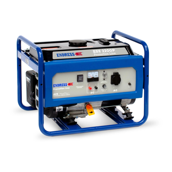
- Page 1 Power Generators ESE 2200 P ESE 3200 P Article No. 290100 Article No. 290101...
- Page 2 Any use or modification beyond the restrictions of the Copyright Act is forbidden and subject to penalty without the consent of ENDRESS Elektrogerätebau GmbH. This applies in particular to copies, translations, microfilming, as well as storage and processing in electronic systems.
-
Page 3: Table Of Contents
Table of Contents Table of Contents Overview / first steps....................5 Intended use .........................5 Included in delivery......................5 Country-specific labels ....................6 Dismantling the transport securing devices ..............6 Safety..........................7 General safety instructions ....................7 Operating elements ....................9 Labels on the generator ....................9 Generator components....................10 Function and mode of operation ..................11 Operation........................12 Mounting the wheelset ....................12... - Page 4 Table of Contents Technical specifications ..................31 Warranty provisions ....................34 Environmental protection ..................1 General note: The illustrations in these operating instructions do not always comply completely with the actual design, in particular with regard to the colour, and are to be considered a representa- tion of basic principles.
-
Page 5: Overview / First Steps
Overview / first steps Intended use Overview / first steps Before operating the generator, read this manual thoroughly, especially its safety instructions. This manual instructs you on basic work with the generator and helps you prevent hazards, repairs and defects. Intended use The generator is designed exclusively for private use and is not suitable for sustained commercial use. -
Page 6: Country-Specific Labels
Overview / first steps Country-specific labels Country-specific labels A set of stickers/labels is delivered with the generator (see p. 5). These must be applied in the language of the country where the device is being used. The standard labels applied are in German. Dismantling the transport securing devices 1. -
Page 7: Safety
Safety General safety instructions Safety This section describes the basic safety regulations for oper- ating the generator. DANGER! High risk! Failure to comply can cause injury or death. CAUTION! Moderate risk! Failure to comply can cause property damage. ATTENTION! Mild risk! Instructions that must be observed when using the device. - Page 8 Safety General safety instructions Shock hazard! Protect the device from dampness and moisture. Operation is only allowed when the device is dry. If the device becomes damp or wet while running, stop it immediately. Operation with existing power supply networks is prohibited.
-
Page 9: Operating Elements
Operating elements Labels on the generator Operating elements Labels on the generator If it has not yet been done, attach the labels in your national language (see p. 6). The following labels must be attached to the generator and be kept in clearly legible condition: Fig. -
Page 10: Generator Components
Operating elements Generator components Generator components Fig. 4: Generator components 1 Dipstick / oil cap Protective contact socket, 230V/ Oil drain screw Earthing connection Motor ON/OFF switch 10 Transport handle, wheelset Circuit breaker (triggered during overload or current leakage): ON position - Device connected. OFF position - Device discon- nected. -
Page 11: Function And Mode Of Operation
Operating elements Function and mode of operation Fig. 5 Generator components 2 Starter handle Tank Fuel valve Tank cover Air filter Function and mode of operation The synchronous generator is firmly coupled to the drive motor. The assembly is installed in a stable frame and equipped with a flexible, low-vibration suspension. -
Page 12: Operation
Operation Mounting the wheelset Operation Mounting the wheelset Requirements The generator must be turned off. • The generator must have cooled down. • No motor oil or petrol has been added. • Connection lines are disconnected. • DANGER! The device may cause severe injury if it falls or slides away. - Page 13 Operation Mounting the wheelset 4. Secure the wheel with a screw (M6) and put the blue protective cap on (see Fig. 7). Fig. 7: Mounting the wheelset 2 5. Fasten the two rubber feet to the U-shaped plates using two nuts and bolts (M8) (see Fig. 8). Fig.
-
Page 14: Transporting The Generator
Operation Transporting the generator 9. Place the cord for the locking pin around the frame (see Fig. 9). 10. Repeat steps 8 and 9 for the other carrying handle. This completes mounting of the wheelset and handles. Fig. 9: Mounting the wheelset 4 Transporting the generator Requirements The generator must be turned off. -
Page 15: Adding / Draining Fuel
Operation Adding / draining fuel The device may cause severe injury if it falls or slides away. Bear in mind that the device weighs approx. 50.5 kg. • Place the device on a non-skid floor and secure it further • (such as with tension straps). - Page 16 Operation Adding / draining fuel Prevent petrol from escaping. • The device is switched off. • The device has cooled down. • Keep open fire and sparks away. • ATTENTION! Escaping petrol can contaminate soil and groundwater. Do not fill the tank completely. •...
-
Page 17: Fill The Generator With Motor Oil
Operation Fill the generator with motor oil Fig. 11: Emptying the petrol tank Emptying the petrol tank 1. Place the collection container next to the generator. 2. Turn the fuel tap to OFF. 3. Open and pull back the petrol hose bracket (see Fig. -
Page 18: Starting The Generator
Operation Starting the generator CAUTION! Leaking motor oil can contaminate soil and groundwa- ter. Do not fill the crankcase to the maximum (check the fill • level with the dipstick). Use a filling tool. • CAUTION! Using the wrong motor oil will destroy the motor. Use SAE10W-40. - Page 19 Operation Starting the generator Ventilation must be adequate. • DANGER! Electric shock, static discharges. To enable the safety devices (residual current circuit breakers), the generator should be earthed, if possible. For this, use a cable as an earthing conductor (at least 2.5 mm in diameter) that is connected to an earthing conductor (such as a metal water or drain pipe, or...
-
Page 20: Connecting / Disconnecting Appliances
Operation Connecting / disconnecting appliances Fig. 12: Start the device Connecting / disconnecting appliances Proceed as follows to connect appliances to the generator. Requirements The device should be fully warmed up. • If possible, turn the appliance off before connecting. •... -
Page 21: Switching The Generator Off
Operation Switching the generator off DANGER! Electric shocks cause injury or death. The generator may not be connected to other energy • distribution systems (e.g. public power supply) or to other energy generation systems (e.g. other generators). All ordinary appliances with 230 V AC current (50 Hz) and a maximum output of 2,200 W can be used. -
Page 22: Cleaning The Generator
Operation Cleaning the generator Fig. 14: Motor switch 1. Set the motor switch to OFF (see Fig. 14 (1)). Switching the motor off 2. If the device will not be operated in the next few minutes, turn off the petrol tap. The device has been switched off. - Page 23 Operation Decommissioning / storing the generator If the device will not be used for an extended period, the Decommissioning the motor oil (see page 25) and the petrol (see page 15) must device be drained. It is best to cover the generator with a cloth. (more than 8 weeks) The device has been decommissioned.
-
Page 24: Maintenance
Maintenance Maintenance plan Maintenance Maintenance plan The maintenance work specified in this summary must be carried out after the indicated time intervals. Maintenance work Time interval in operating hours [h] before every 50 hours every 100 every 300 each start or 3 months hours or 6 hours or... -
Page 25: Motor Oil
Maintenance Motor oil Motor oil Requirements The generator must be on level ground. • The motor must not be hot, but should ideally be slightly • warm. Place a small pan or rag under the screw plug or dipstick, • in order to catch the escaping oil. -
Page 26: Air Filter
Maintenance Air filter 1. Screw the dipstick out of the motor (see Fig. 14 (2)). 2. Wipe the oil from the dipstick with a lint-free cloth. 3. Screw the clean dipstick completely back in, and then immediately back out. 4. If the oil level is outside the marks (see Fig. 14 (1)), oil must be added. - Page 27 Maintenance Air filter 1. Open the brackets above and below the air filter, and remove the lid (see Fig. 15). 2. Carefully remove the air filter insert (see Fig. 15 (1)). Meanwhile, make sure that no dirt gets into the carburet- tor.
-
Page 28: Spark Plug
Maintenance Spark plug Spark plug Spark plug type Use only the following products: NHSP LD F6RTC • NGK BPR6ES • Champion RN11YC • Requirements The included tool • A cool motor • Fig. 16: Spark plug connector Checking the spark plug How to check the spark plug: 1. - Page 29 Maintenance Spark plug Fig. 17: Electrode gap 5. Slide the spark plug connector onto the spark plug and Checking the ignition press it to the valve cover (see Fig. 17). spark Make sure that metal touches metal, so that no electrical connection is possible.
-
Page 30: Troubleshooting
Troubleshooting Troubleshooting Malfunction Possible cause Correction The machine does not No fuel Check the fuel (see p. 15) start Fuel tap in OFF position Set the fuel tap to the open ON position. Rocker switch in OFF position Set the rocker switch to ON. Spark plug socket dirty or Clean the spark plug socket. -
Page 31: Technical Specifications
Technical specifications Technical specifications Designation Value Unit Type ESE 2200 P ESE 3200 P Max. output 2200 2800 Nominal output 2000 2500 Nominal frequency [Hz] Nominal speed 3000 3000 [rpm] Rated voltage Rated current 10.9 Weight (empty) 40.5 48.5 [kg]... - Page 32 Technical specifications ENDRESS Elektrogerätebau GmbH Explanation of the model ESE 2200 P Neckartenzlinger Straße 39 plate Generator set ISO 8528 D-72658 Bempflingen, Germany Pr (COP) 2.2 kW S / N 290100 / 00001 cos φr 1.0 fr 50Hz Ur 1~ 230 V Ir 8.7 A...
- Page 33 Technical specifications Declaration of Conformity...
-
Page 34: Warranty Provisions
Warranty provisions Warranty provisions For commercial use, the warranty period is six months from the date of purchase. For warranty claims or replacement parts, please contact the dealer from whom the product was purchased. Always be sure to include the following documents with your defec- tive device: Proof of purchase (receipt or invoice) •... - Page 35 Warranty provisions Tel.: +49(0)71 23-9737-44 E-mail: Service@endress-stromerzeuger.de ENDRESS Elektrogerätebau GmbH Neckartenzlinger Straße 39D 72658 Bempflingen Tel.: +49-(0)-71 23-9737-0 Fax: +49-(0)-71 23-9737-1 0 E-mail: Info@endress-stromerzeuger.de www.endress-stromerzeuger.de...
-
Page 36: Environmental Protection
Environmental protection Environmental protection The packaging material must be recycled according to the environmental regulations applicable at the place of use. The workplace must be protected against contamination by leaking operating fluids. Used or leftover fuels and lubricants must be recycled ac- cording to the environmental regulations applicable at the place of use.
Need help?
Do you have a question about the ESE 2200 P and is the answer not in the manual?
Questions and answers