
Related Manuals for Telegroup PCRL8/14


Summary of Contents for Telegroup PCRL8/14
- Page 1 // ENG // User Manual // PFC Controller PCRL8/14 Automatic PFC systems Automatic PFC systems all Series...
- Page 2 Sig. Fabiano Bagnoli MUM- TL TLF ____________________ ___________________ ________________ ©2018 Telegroup S.r.l. The contents of this manual are protected by copyright owned by the publisher; reproduction is forbidden (also partial) without authorization. The information contained in this manual is accurate, but we accept no responsibility for any errors or errors omissions.
-
Page 3: Table Of Contents
INDEX 1. INTRODUCTION 5 1.1. Purpose of the Instruction Manual 5 1.2. Recipients 6 1.3. Storage of the Instruction Manual 6 1.4. Definitions and pictograms 6 ... 7 2. SAFETY INSTRUCTIONS 8 2.1. Transport and storage 9 2.2. Positioning 9 2.3. - Page 4 ANNEX Wiring Diagram Declarations of conformity Test certificate Warranty certificate p. 4 / 43...
-
Page 5: Introduction
The sequence of the chapters responds to the temporal logic of the product life. Telegroup S.r.l. having the responsibility to ensure that they are actually present in the points of use, only the updated versions of the Manual make available the updated versions of the manual on the Site www.telegroup.it. -
Page 6: Recipients
1.2 Recipients The manual in question is addressed to Installers, Operators, Maintenance Managers and to all personnel who can intervene or interface with the machine at any level. It is divided into autonomous chapters aimed at specific figures for which the skills have been defined, necessary to operate on the machine in safe conditions. - Page 7 OPERATOR: The person in charge of installing, operating, regulating, cleaning, repairing and moving a machine and carrying out its maintenance; DANGER: A potential source of injury or damage to health; HAZARDOUS AREA: Any area inside and / or near a machine where the presence of a person constitutes a risk to the safety and health of that person;...
-
Page 8: Safety Instructions
2.1 Transportation and storage Telegroup S.r.l. assumes no responsibility if the equipment is moved without the appropriate packaging, which however does not ensure impermeability to water, dust and aggressive chemical agents Transport the machine with lifting equipment suitable for the dimensions and weight of the machine. -
Page 9: Positioning
2.2 Positioning Transferring the panel directly from a cold to a warm environment can cause condensation. Before being installed it must be absolutely dry. Please allow an acclimatization time of at least two hours. Do not install near water or in damp environments. Do not install in places near heat sources. -
Page 10: Operation And Maintenance
Disconnect the mains power supply before carrying out any service or repair. Check that there is no dangerous voltage inside. 3. GENERAL INFORMATION 3.1 Identification of the manufacturer MANUFACTURER Telegroup S.r.l. Via L. Da Vinci, 100 - Loc. Sambuca 50028 TAVARNELLE VAL DI PESA (FI) - ITALIA CONTACTS Tel. 055-8071267 / 8071118... -
Page 11: Statement
In order to take advantage of repairs under warranty, the purchaser must in any case ship the appliance to the manufacturer (Telegroup Srl Loc. Sambuca 50028 Tavarnelle Val di Pesa (FI)). The costs for shipping the product to be repaired or replaced are the responsibility of the purchaser; these products are therefore supplied ex-works of the seller. -
Page 12: Warranty
incorrect power supply incorrect installation natural events (Lightning etc. ..) It is recalled that modifications to safety devices and systems and any intervention other than ordinary and extraordinary maintenance, carried out without the express written authorization of the manufacturer, render the warranty void and relieve the manufacturer from any liability for damage caused by the defective product. -
Page 13: Technical Data Of The Equipment
4.3 Technical data of the equipment On the product identification plate, the essential technical data are shown (General characteristics, Characteristics of capacitors Characteristics of power factor correction regulators), 4.4 Sound Emissions The A-weighted equivalent continuous sound pressure level in the work stations does not exceed 45 db (A) during the working phase;... - Page 14 Power KVAR Icc max kA Vcc% Icc kA Da 7.5 a 40 Da 45 a 55 Da 65 a 75 5,77 Da 87.5 a 250 7,22 Da 275 a 400 9,02 Da 450 a 750 11,37 14,43 18,04 22,73 19,25 24,06 1000 30,07...
- Page 15 • The phase sequence (R (L1) - S (L2) -T (L3)) must be respected when connecting the line to the power factor correction panel. • This condition can be easily checked with the aid of a voltmeter: by measuring, between the phase where the C.T. (the R) and the phase anchored on the R terminal of the automatic power factor correction switch, the voltage must be "0".
-
Page 16: Adjustments
6.1 INSTRUCTIONS FOR USE OF THE PCRL5/7 POWER FACTOR REGULATOR The PCRL8/14 is an automatic rephasing controller based on a microprocessor control circuit, able to perform the insertion or disconnection of the capacitor banks necessary to reach and maintain the average power factor set. - Page 17 • Automatic microprocessor power factor regulator. • LED display, 3-digit 7 segments. • 4-button membrane keyboard. • TTL-RS232 serial interface for set-up and automatic test by PC. • Internal temperature sensor. • Advanced functions (capacitor overload current measurement, average weekly power factor, maximum value storage).
-
Page 18: Introduzione
Manual revision history Introduzione Introduction Il regolatore automatico del fattore di potenza PCRL8/14 è stato progettato The PCRL8/14 automatic power factor control unit has been designed to incorporando lo stato dell’arte delle funzioni richieste per le applicazioni di offer state-of-the-art functions for power factor compensation applications. -
Page 19: Descrizione
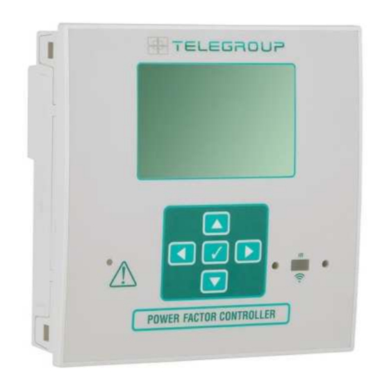
Backlit LCD icon screen. Versioni: Versions: PCRL8/14 con 8 gradini, espandibile a 14 max. PCRL8/14 with 8 relays, expandable to 14 max. 5 tasti di navigazione per funzioni ed impostazioni. 5 navigation keys for function and settings. -
Page 20: Modi Operativi
Via L. Da Vinci, 100, 50028, Tavarnelle V.P. – Loc. Sambuca (FI) – ITA, P.IVA 0438 634 0485 Ph +39 0558071267 Fax.+ 39 0558071338 telegroup@telegroup.it www.telegroup.it Modi operativi Operating modes Esistono tre possibili modi operativi, elencati di seguito: There are three possible operating modes, listed below:... -
Page 21: Misure
Misure Measures La PCRL8/14 fornisce una serie di misure visualizzate sul display The PCRL8/14 provides a set of measurements displayed on the alfanumerico, in abbinamento al cosfi attuale che rimane sempre alphanumeric display, in conjunction with the current cosphi that is visualizzato sul display principale. -
Page 22: Blocco Tastiera
LOC to indicate the locked keypad state. Espandibilità Expandability Grazie al suo bus di espansione, la PCRL8/14 può essere espansa con Thanks to expansion bus, the PCRL8/14 can be expanded with two due moduli aggiuntivi della serie EXP…. -
Page 23: Porta Di Programmazione Ir
IR programming port La configurazione dei parametri della PCRL8/14 si può effettuare tramite The parameters of the PCRL8/14 can be configured through the front la porta ottica frontale, attraverso la chiavetta di programmazione IR- optical port, using the IR-USB code CX01 programming dongle, or with USB codice CX01 oppure la chiavetta IR-WiFi codice CX02. -
Page 24: Impostazione Parametri Da Pc, Tablet O Smartphone
PC: You can use the Xpress or Synergy software to transfer trasferimento dei parametri di set-up (precedentemente impostati) da (previously programmed) set-up parameters from the PCRL8/14 to the PCRL8/14 al disco del PC e viceversa. hard drive of the PC and vice versa. -
Page 25: Impostazione Rapida Ta
(restore) nella memoria di lavoro. I comandi di copia di PCRL8/14. This data can be restored when necessary in the work sicurezza e ripristino dei dati sono disponibili nel Menu comandi. -
Page 26: Tabella Dei Parametri
Via L. Da Vinci, 100, 50028, Tavarnelle V.P. – Loc. Sambuca (FI) – ITA, P.IVA 0438 634 0485 Ph +39 0558071267 Fax.+ 39 0558071338 telegroup@telegroup.it www.telegroup.it Tabella dei parametri Parameter table Di seguito vengono riportati tutti i parametri di programmazione ... - Page 27 Via L. Da Vinci, 100, 50028, Tavarnelle V.P. – Loc. Sambuca (FI) – ITA, P.IVA 0438 634 0485 Ph +39 0558071267 Fax.+ 39 0558071338 telegroup@telegroup.it www.telegroup.it Utilizzabile solo quando l’impianto non ha alcun dispositivo generatore. working with only one CT and when the system has no generator device.
- Page 28 Via L. Da Vinci, 100, 50028, Tavarnelle V.P. – Loc. Sambuca (FI) – ITA, P.IVA 0438 634 0485 Ph +39 0558071267 Fax.+ 39 0558071338 telegroup@telegroup.it www.telegroup.it Unità di misura °C °Celsius Temperature unit of °C °Celsius P.36 °C P.36 °C temperatura °F °Fahrenheit...
- Page 29 Via L. Da Vinci, 100, 50028, Tavarnelle V.P. – Loc. Sambuca (FI) – ITA, P.IVA 0438 634 0485 Ph +39 0558071267 Fax.+ 39 0558071338 telegroup@telegroup.it www.telegroup.it P.26 – P.27 – Tolleranza intorno al setpoint. Quando il cosfi si trova all’interno della variation.
-
Page 30: Allarmi
In seguito al verificarsi di uno o più allarmi, la PCRL8/14 ha un In the case of one or more alarms, the behaviour of the PCRL8/14 comportamento dipendente dalla impostazione delle proprietà degli depends on the properties settings of the active alarms. -
Page 31: Proprietà Di Default Allarmi
Via L. Da Vinci, 100, 50028, Tavarnelle V.P. – Loc. Sambuca (FI) – ITA, P.IVA 0438 634 0485 Ph +39 0558071267 Fax.+ 39 0558071338 telegroup@telegroup.it www.telegroup.it bassa soglia impostata con P.42. overload overload is higher than threshold set with P.32 and P.33. After the alarm Tensione impianto troppo La tensione misurata è... -
Page 32: Menu Comandi
▲ fino alla fine del countdown il comando viene selected command. PCRL8/14 shows OK? with a countdown. eseguito, mentre se si rilascia prima il tasto il comando viene annullato. Per uscire dal menu comandi premere e tenere premuto AUT. -
Page 33: Utilizzo Dongle Cx02
Press 3 times consecutively and fast the dongle button. A questo punto il display della PCRL8/14 visualizza il primo dei possibili At this point the display of the PCRL8/14 shows the first of the 6 comandi (D1…D6). -
Page 34: Schemi Di Collegamento
Via L. Da Vinci, 100, 50028, Tavarnelle V.P. – Loc. Sambuca (FI) – ITA, P.IVA 0438 634 0485 Ph +39 0558071267 Fax.+ 39 0558071338 telegroup@telegroup.it www.telegroup.it Schemi di collegamento Wiring diagrams ATTENZIONE!! WARNING! Togliere sempre tensione quando si opera sui morsetti. -
Page 35: Disposizione Morsetti
Via L. Da Vinci, 100, 50028, Tavarnelle V.P. – Loc. Sambuca (FI) – ITA, P.IVA 0438 634 0485 Ph +39 0558071267 Fax.+ 39 0558071338 telegroup@telegroup.it www.telegroup.it Sovraccarico condensatori 1 misura calcolata su L1-N Capacitor overload current measure 1 reading calculated on L1-N Impostazione parametri P.03 = L1... -
Page 36: Dimensioni Meccaniche E Foratura Pannello
Via L. Da Vinci, 100, 50028, Tavarnelle V.P. – Loc. Sambuca (FI) – ITA, P.IVA 0438 634 0485 Ph +39 0558071267 Fax.+ 39 0558071338 telegroup@telegroup.it www.telegroup.it Dimensioni meccaniche e foratura pannello (mm) Mechanical dimensions and panel cutout (mm) Caratteristiche tecniche... -
Page 37: Cronologia Revisioni Manuale
Via L. Da Vinci, 100, 50028, Tavarnelle V.P. – Loc. Sambuca (FI) – ITA, P.IVA 0438 634 0485 Ph +39 0558071267 Fax.+ 39 0558071338 telegroup@telegroup.it www.telegroup.it Uscite a relè OUT 8 Relay output OUT 8 Tipo di contatto 1 contatto scambio... - Page 38 Via L. Da Vinci, 100, 50028, Tavarnelle V.P. – Loc. Sambuca (FI) – ITA, P.IVA 0438 634 0485 Ph +39 0558071267 Fax.+ 39 0558071338 telegroup@telegroup.it www.telegroup.it...
- Page 39 Via L. Da Vinci, 100, 50028, Tavarnelle V.P. – Loc. Sambuca (FI) – ITA, P.IVA 0438 634 0485 Ph +39 0558071267 Fax.+ 39 0558071338 telegroup@telegroup.it www.telegroup.it...
- Page 40 Via L. Da Vinci, 100, 50028, Tavarnelle V.P. – Loc. Sambuca (FI) – ITA, P.IVA 0438 634 0485 Ph +39 0558071267 Fax.+ 39 0558071338 telegroup@telegroup.it www.telegroup.it...
- Page 41 Ph +39 0558071267 Fax.+ 39 0558071338 telegroup@telegroup.it www.telegroup.it Via L. Da Vinci, 100, 50028, Tavarnelle Val di Pesa – Loc. Sambuca – FIRENZE - ITALY – TELEGROUP S.r.l. Phone +39 055 80 71 267 /118 Fax. + 39 055 80 71 338 www.telegroup.it...
- Page 42 TELEGROUP capacitors are made without PCBs, in compliance with decree n. 216 of 24.05.88. Capacitors not in use and out of service must be disposed of according to the local laws and regulations in force in each country and in accordance with the European Directives.
-
Page 43: Intended Use
Electrical and the Equipment For the choice of the most suitable type of equipment for your system contact Telegroup TECHNICAL ASSISTANCE. S.r.l .. The Equipment must be used correctly in order to ensure the initial degree of safety. -
Page 44: Maintenance
9. MAINTENANCE 9.1 Ordinary and extraordinary maintenance Premise The information in this paragraph is given in compliance with CEI EN 61439-1 prf. 6.2.2. Maintenance and repair must be carried out by SPECIALIZED personnel and "TRAINED PERSONS". Maintenance and repair that are not carried out properly can be a source of serious danger to the user. Before starting maintenance and repair operations, carefully read the instructions in this Technical Manual to avoid damage to people, pets and property. - Page 45 clean the panel from dust or other, taking particular care of all those components that could create insulation problems (busbar supports, capacitor plates, etc.). check the absence of condensation on the live components. check the integrity of the insulation relative to the power and auxiliary cables. ascertain the correct functioning of the electronic regulator, by performing the manual insertion of the batteries and checking the closing of the contactors corresponding to the individual outputs.
-
Page 46: Assistance
For questions and / or problems, call the After Sales assistance office at one of the following telephone numbers, asking for a technical representative: Tel. 055-8071267 Tel. 055-8071118 Or send an email to the following address: service@telegroup.it Please keep the following information at hand: • Model number and serial number • Date of the Fault or the Problem •... -
Page 47: Emergency Situations
10. EMERGENCY SITUATIONS To switch off the equipment quickly, use the circuit breaker located on the distribution board never the main switch-off of the power factor correction equipment. In the event of a fire in the environment where the appliance is installed, do not use water or any means that could compromise the integrity of the appliance (such as dust extinguishers). - Page 48 ----------------------------------------------------------------------------------------- ----------------------------------------------------------------------------------------- ----------------------------------------------------------------------------------------- ----------------------------------------------------------------------------------------- ---------------------------------------------------------------------------------------- ----------------------------------------------------------------------------------------- ----------------------------------------------------------------------------------------- ----------------------------------------------------------------------------------------- ----------------------------------------------------------------------------------------- ----------------------------------------------------------------------------------------- ----------------------------------------------------------------------------------------- ----------------------------------------------------------------------------------------- ----------------------------------------------------------------------------------------- ----------------------------------------------------------------------------------------- ----------------------------------------------------------------------------------------- ----------------------------------------------------------------------------------------- ----------------------------------------------------------------------------------------- ----------------------------------------------------------------------------------------- ----------------------------------------------------------------------------------------- ----------------------------------------------------------------------------------------- ----------------------------------------------------------------------------------------- ----------------------------------------------------------------------------------------- ----------------------------------------------------------------------------------------- ----------------------------------------------------------------------------------------- ----------------------------------------------------------------------------------------- ----------------------------------------------------------------------------------------- ----------------------------------------------------------------------------------------- ----------------------------------------------------------------------------------------- ----------------------------------------------------------------------------------------- ----------------------------------------------------------------------------------------- ----------------------------------------------------------------------------------------- ----------------------------------------------------------------------------------------- ----------------------------------------------------------------------------------------- ----------------------------------------------------------------------------------------- ----------------------------------------------------------------------------------------- ----------------------------------------------------------------------------------------- ----------------------------------------------------------------------------------------- ----------------------------------------------------------------------------------------- ----------------------------------------------------------------------------------------- p. 40 / 43...
- Page 49 ----------------------------------------------------------------------------------------- ---------------------------------------------------------------------------------------- p. 41 / 43...
- Page 50 p. 42 / 43...
- Page 51 TELEGROUP S.r.l. Via L. Da Vinci, 100, 50028, Tavarnelle Val di Pesa – Loc. Sambuca – FIRENZE - ITALY – Phone +39 055 80 71 267 /118 Fax. + 39 055 80 71 338 www.telegroup.it telegroup@telegroup.it p. 43 / 43...
Need help?
Do you have a question about the PCRL8/14 and is the answer not in the manual?
Questions and answers