Table of Contents
Advertisement
Quick Links
Vespa would like to thank you
for choosing one of its products. We have prepared this manual to help you to get the very best from your vehicle. Please read it carefully before riding
the vehicle for the first time. It contains information, tips and precautions for using your vehicle It also describes features, details and devices to assure
you that you have made the right choice. We believe that if you follow our suggestions, you will soon get to know your new vehicle well and that it will
continue to give you satisfactory service for many years to come. This booklet forms an integral part of the vehicle; should the vehicle be sold, it must
be transferred to the new owner.
Vespa GTS Supertech 300 hpe
Ed. 03_04/2019 Cod. 1Q000743 (IT-FR-DE-ES-NL-EN -PT-EL)
Advertisement
Table of Contents

Related Manuals for VESPA GTS Supertech 300 hpe


Summary of Contents for VESPA GTS Supertech 300 hpe
- Page 1 Vespa would like to thank you for choosing one of its products. We have prepared this manual to help you to get the very best from your vehicle. Please read it carefully before riding the vehicle for the first time. It contains information, tips and precautions for using your vehicle It also describes features, details and devices to assure you that you have made the right choice.
- Page 2 The instructions given in this manual are intended to provide a clear, simple guide to using your vehicle; details are also given of routine maintenance procedures and regular checks that should be carried out on the vehicle at an Authorised PIAGGIO Dealer or Service Centre. The booklet also contains instructions for simple repairs.
- Page 3 Personal safety Failure to completely observe these instructions will result in serious risk of personal injury. Safeguarding the environment Sections marked with this symbol indicate the correct use of the vehicle to prevent dam- aging the environment. Vehicle intactness The incomplete or non-observance of these regulations leads to the risk of serious damage to the vehicle and sometimes even the invalidity of the guarantee.
-
Page 5: Table Of Contents
INDEX VEHICLE..................Running in................. 67 Dashboard................Starting up the engine............... 67 Analogue instrument panel............Precautions................69 Digital lcd display..............11 Difficult start up................. 69 *MODE* button..............38 Stopping the engine..............70 Keyswitch.................. 39 Catalytic silencer............... 71 Locking the steering wheel............ 39 Stand.................. - Page 6 Front and rear disc brake............100 Puncture..................101 Inactivity of the vehicle.............. 102 Cleaning the vehicle..............102 Troubleshooting................ 106 TECHNICAL DATA..............109 Data..................110 SPARE PARTS AND ACCESSORIES........115 Warnings................... 116 SCHEDULED MAINTENANCE............ 119 Scheduled servicing table............120 Recommended products............122 SPECIAL FITTINGS..............
-
Page 7: Vehicle
Vespa GTS Supertech 300 hpe Chap. 01 Vehicle... -
Page 8: Dashboard
Dashboard (01_01) 01_01... -
Page 9: Analogue Instrument Panel
A = Instrument panel B = Front brake lever C = Throttle grip D = ASR button E = Engine stop switch F = Starter button G = Ignition switch H = Bag hook I = Saddle opening button L = Joystick MODE M = Horn button N = Turn indicator control O = Light switch... - Page 10 01_02 A = Turn signal indicator light B = High-beam indicator light C = Engine control indicator light...
-
Page 11: Digital Lcd Display
D = Engine stop indicator light E = Immobilizer indicator light F = Digital display light sensor; G = Low engine oil pressure warning light H = ABS warning light I = Coolant temperature high warning light L = Digital display Digital lcd display (01_03, 01_04, 01_05, 01_06, 01_07, 01_08, 01_09, 01_10, 01_11, 01_12, 01_13, 01_14, 01_15, 01_16, 01_17, 01_18, 01_19, 01_20, 01_21, 01_22, 01_23, 01_24, 01_25, 01_26,... - Page 12 01_03 Key: A = Speedometer...
- Page 13 B = Ambient temperature indicator C = Ice hazard icon D = Multifunctional panel E = «Vespa MIA» icon panel F = Graphics and infotainment panel G = Service icon H = ASR warning light I = Reserve fuel tank warning light...
- Page 14 "PRESS AND HOLD": PRESS THE BUTTON AND HOLD FOR AT LEAST 2 SEC- ONDS. MAINTENANCE ICON This function indicates the scheduled maintenance interventions. For each time the key is turned to "ON", once the instrument panel has performed the initial check, if the value of the remaining kilometres until the next intervention is less than 300 Km (186.41 mi), the indicated icon will flash for 5 seconds.
- Page 15 MULTIFUNCTIONAL PANEL The multifunction panel displays the following information cyclically by briefly pressing the MODE joystick up or down: N.B. "PRESS BRIEFLY AND RELEASE": PRESS THE BUTTON AND RELEASE WITH- IN 0.5 SECONDS; 01_07 "PRESS AND HOLD": PRESS THE BUTTON AND HOLD FOR AT LEAST 2 SEC- ONDS.
- Page 16 While displaying one of the functions: - trip odometer - travel time - maximum speed - average speed - average consumption all values are reset with a prolonged press of the MODE joystick towards the CEN- 01_09 TRE. SETTINGS MENU With the vehicle stationary, press the joystick up or down to display the «settings»...
- Page 17 LANGUAGE SETTING Briefly press the joystick up or down to highlight the desired function. Select the de- sired language via a short press on the centre button of the joystick. The selection excludes the others. 01_12 CONFIGURATION MENU Highlight the "Configuration" function via a short press on the central button of the joystick;...
- Page 18 WARNING DISCONNECTING THE BATTERY CABLES WILL RESULT IN A RESET OF THE CLOCK Select the desired format between 12h or 24h. A selection excludes the others. 01_15 Highlight the "Set time" function via a short press on the central button of the joystick; enter the menu.
- Page 19 Highlight the "Hour" function. Via a short press on the centre button of the joystick, enter the menu. 01_17 Briefly press the joystick up or down to set the correct hour. Press the joystick in the centre briefly to confirm. The green bar confirms the choice. 01_18 Highlight the 'Minutes"...
- Page 20 Briefly press the joystick up or down to set the correct minutes. Press the joystick in the centre briefly to confirm. The green bar confirms the choice. 01_20 UNITS MENU Highlight the «Units» function via a short press on the central button of the joystick; enter the menu where it is possible to configure: - Speed - Temperature...
- Page 21 Select the desired format between Km/h or mph. A selection excludes the others. 01_23 TEMPERATURE UNIT SETTING Highlight the "Temperature" function. Via a short press on the centre button of the joystick, enter the menu. 01_24 Select the desired format between °C or °F. A selection excludes the others. 01_25...
- Page 22 PAIRING CONFIGURATION MENU The vehicle is equipped with the «Vespa MIA» ECU which communicates with the smartphone via Bluetooth. Using the special "Vespa" application installed on the smartphone, it is possible to exchange data with the vehicle and manage multimedia contents.
- Page 23 The message confirming that pairing with the smartphone is enabled appears on the digital display. Enable the bluetooth search on your smartphone, select the "BT- ROUTER" device, if required, enter the password "0000" and press on pair. 01_29 The "BT-ROUTER" device will be visible in the list of associated devices on the smart- phone.
- Page 24 "Pairing reset" function and briefly press the central button of the joystick. 01_31 All stored Bluetooth devices are deleted from the «Vespa MIA» system. The message confirming the cancellation is displayed on the digital display. You can repeat the procedure to pair the smartphone.
- Page 25 RECEIVED ON THE DISPLAY. CONNECTION BETWEEN THE APPLICATION AND THE DIGITAL DISPLAY Search for the «Vespa» application from the Play Store or App Store, and install it. Register your account by following the instructions. Select "allow" for the position and notifications management requests.
- Page 26 Activate the "pairing" mode of the bluetooth headset to be paired (refer to the in- structions of the device itself). Press the Bluetooth icon on the main screen of the «Vespa» application and perform a new search for devices until the headset is dis- played. Select the bluetooth headset, check the "Handsfree/driver headset" option and press "Pair".
- Page 27 THIS OPERATION IS NECESSARY WHEN YOU HAVE TO REPLACE THE SMARTPHONE. 01_37 All stored Bluetooth devices are deleted from the «Vespa MIA» system. The message confirming the cancellation is displayed on the digital display. You can repeat the pro- cedure to pair the new smartphone.
- Page 28 BACKLIGHT MENU Highlight the "Backlight" function via a short press on the central button of the joystick; enter the menu where it is possible to configure: - Backlight mode between Automatic, Day, Night - Brightness level (Settings) 01_39 Briefly press the joystick up or down to highlight the desired function. Confirm the selected option with a short press of the centre button of the joystick.
- Page 29 Highlight the "Setting" function. Via a short press on the central button of the joystick, enter the menu. 01_42 Highlight the "Day" function. Via a short press on the centre button of the joystick, enter the menu. The default value is 4. 01_43 Briefly press the joystick up or down to set the desired brightness level.
- Page 30 Highlight the "Night" function. Via a short press on the centre button of the joystick, enter the menu. The default value is 3. 01_45 Briefly press the joystick up or down to set the desired brightness level. Press the joystick in the centre briefly to confirm. The green bar confirms the choice. 01_46 GRAPHIC MENU Highlight the "Graphic"...
- Page 31 01_48 "VESPA MIA" SYSTEM MESSAGES The "Vespa MIA" system communicates with the user by means of messages dis- played on the graphic panel of the digital display. Depending on the message type, the graphic panel shows the icon, colours and the specific message. The image on the side shows: - Text alarms, contact an Authorised Service Centre;...
- Page 32 To use call functions, view notifications and identifications of the caller, you need to: - pair the smartphone with the «Vespa MIA» system via bluetooth as described above; - install and access with your account the «Vespa» application on the smartphone;...
- Page 33 The information on the digital display are: - call in progress; - call ended; - SMS, email, generic notification; - voice control active. 01_51 Use the MODE joystick to manage the calls as shown in the table: MODE JOYSTICK FUNCTIONS FOR CALL MANAGEMENT Accept incoming call PRESS CENTRE BUTTON OF...
- Page 34 MANAGEMENT OF THE MUSIC PLAYBACK To use the music playback functions, you need to: - pair the smartphone with the «Vespa MIA» system via bluetooth as described above; - install and access with your account the «Vespa» application on the smartphone;...
- Page 35 The information on the digital display are: - track playing; - playback paused; - playback interrupted; - scroll forward (or backward) of the track. WARNING 01_53 THE OPENING OF A PLAYLIST SHOULD BE MADE FROM THE SMARTPHONE BEFORE TRAVELLING OR THROUGH VOCAL COMMANDS IF YOU ARE ON THE MOVE.
- Page 36 BUTTON OF SELECTOR GPS NAVIGATION. The «Vespa MIA» system, paired with the «Vespa» application, allows GPS indica- tions to be shown on the digital display. The desired destination can be reached by means of pictograms, distance data and travel times.
- Page 37 "PRESS AND HOLD": PRESS THE BUTTON AND HOLD FOR AT LEAST 2 SEC- ONDS. 01_56...
-
Page 38: Mode* Button
NAVIGATION SCREEN KEY A = destination address or next turn; B = direction after the next turn; C = distance to the next turn; D = time remaining to arrival at destination; E = distance remaining to arrival at destination; F = direction of next turn;... -
Page 39: Keyswitch
"PRESS AND HOLD": PRESS THE BUTTON AND HOLD FOR AT LEAST 2 SEC- ONDS. Keyswitch (01_58) The ignition switch is located on the front leg shield back plate near the bag hook. SWITCH POSITIONS ON «1»: Ready to start position, non-extractable key, mechanical anti-theft device disabled. -
Page 40: Releasing The Steering Wheel
Releasing the steering wheel (01_60) Reinsert the key and turn it to «OFF». CAUTION NEVER TURN THE KEY TO «LOCK» OR «OFF» WHILE RIDING. 01_60 Switch direction indicators (01_61) Move the switch «A» towards the left to indicate a left turn; move the switch «A» towards the right to indicate a right turn;. -
Page 41: Horn Button
Horn button (01_62) Press button «A» to operate the horn. 01_62 Light switch (01_63) The low beam headlamp is lit when the light selector switch A is turned to 0. Turning the switch to 1 turns on the high beam headlamp. CAUTION DO NOT REST OR TRANSPORT OBJECTS AND/OR CLOTHING ON TOP OF THE FRONT LIGHT ASSEMBLY WITH THE LIGHT ON OR JUST TURNED OFF. -
Page 42: Start-Up Button
Start-up button (01_64) Starter button «A». To start the vehicle see the "starting the engine" section. 01_64 Engine stop button (01_65) With the emergency stop switch «A» in position «1» RUN it is possible to start the engine; if the emergency stop switch «A» is in position «0» OFF it is not possible to start the engine, and if it is running, it will stop. -
Page 43: System Abs
System ABS (01_66, 01_67, 01_68) The vehicle is equipped with a locking ABS system on the wheels. A: Tone wheel B: Speed sensor • ABS: It is a hydraulic - electronic device that limits the pressure within the braking circuit when a sensor, located on the wheel, detects its tendency to lock. -
Page 44: System Asr
When switching the key to «ON», the ABS control unit performs a control of the sys- tem, during which the ABS warning light flashes. This phase ends when exceeding 5 Km/h of speed with the switching off of the warning light. In case of error of the system, the ABS warning light remains fixed. - Page 45 FOR THE CALIBRATION OF THE CONTROL UNIT PERFORM THE PROCEDURE BELOW. ASR BUTTON 1: activation / deactivation. 01_69 ASR ICON 2: ASR status indicator icon. 01_70 ASR ICON FLASHING MODE: - Frequency of 5 flashes per second (5Hz), with vehicle running: The system is func- tioning correctly and is active (poor grip conditions, engine power limiting in effect);...
- Page 46 - Frequency of 1 flash per second (2 Hz), with the key in "ON" position and the vehicle at a standstill: The system is active and the calibration is performed. The specific icon will switch off as soon as the ABS system is operational. - Frequency of 1 flash every 2 seconds (0.5 Hz), with the key in "ON"...
- Page 47 WARNING THE ASR SYSTEM IS ACTIVATED AT EVERY "ON" POSITIONING OF THE IGNI- TION SWITCH. IF DISABLED BY THE USER, THE ASR SYSTEM KEEPS THE STATE OF INAC- TIVITY ONLY IF THE VEHICLE IS OFF, BY USING THE ENGINE STOP SWITCH; AT THE NEXT KEY ON THE ASR SYSTEM IS ENABLED AUTOMATICALLY.
- Page 48 N.B. THE DEVICE PREVENTS IMPRESSING ON THE REAR HIGH SPEED ROTATION WHEEL WITH THE VEHICLE ON THE CENTRE STAND. IT IS RECOMMENDED NOT TO INSIST WITH THE THROTTLE GRIP IN THIS PARTICULAR CONDITION. CAUTION A POOR STATE OF MAINTENANCE OF THE TYRES CAN RESULT IN ABNOR- MAL OPERATION OF THE ASR SYSTEM.
-
Page 49: The Immobilizer System
3. Turn the ASR system off by pressing the specific button "1" on the handlebar and check that the ASR disabling icon "2" stays on steady. 4. Press at the same time the engine starter button and the ASR on/off button "1"... -
Page 50: Keys
Keys (01_71) The vehicle is supplied with two types of keys. The «A» key with a brown grip and the "MASTER" key. Only a single copy of this key is supplied, which is necessary to pro- gram all the other keys and for the dealer to perform some maintenance operations. For this reason it is recommended that you use it only in exceptional circumstances. -
Page 51: Programming The Immobilizer System
cannot be started, an Authorised Piaggio Service Centre with the electronic equip- ment necessary to identify the problem and repair the system must be contacted. When requesting additional keys, remember that the registration (up to a maximum of 3 keys) must be performed for all the keys, including the news ones and those already in your possession. - Page 52 INTERMEDIATE PHASE After having removed the "MASTER" key, insert the secondary key to be programmed within 10 seconds, and immediately turn it to the "ON" position. Leave the key in this position for 1 to 3 seconds, then turn it to the "CLOSE" position and remove it. In this way you can program up to 3 keys, by repeating the above operation and respecting the indicated times.
-
Page 53: Saddle Opening Remote Control
Saddle opening remote control (01_74) The vehicle is equipped with a remote control to open the saddle and for the recog- nition of the vehicle itself. This remote control is supplied together with the keys and it has been programmed to control the opening device control unit at the manufacturing stage. -
Page 54: Remote Control Programming
Remote control programming (01_75) To program the new radio commands, do the following: 1. disconnect the battery of the vehicle; 2. reconnect the battery of the vehicle; 3. within 5 seconds of reconnecting the battery, simultaneously press buttons "1" and "3" on the remote control twice. the «Bike Finder» device will confirm the process with an optical signal by the quick flashing of the turn indicator;... -
Page 55: Usb Socket
RESTORE FUNCTIONS SIMPLY PRESS THE ACTIVATION BUTTON ON THE RE- MOTE CONTROL FOR ABOUT 3 SECONDS, AS DESCRIBED ABOVE. USB socket (01_76) On vehicles with this feature, a USB port A is situated inside the glove compartment, on the left hand side. To use it, remove the protective cap. -
Page 56: Opening The Saddle To Access The Helmet Compartment By Remote Control
USB port Output voltage (5.00±0.25) Vdc Charging current 500mA max Opening the saddle to access the helmet compartment by remote control (01_77) The vehicle is equipped with a remote control to open the saddle and for the recog- nition of the vehicle itself. •... -
Page 57: Opening The Saddle
Opening the saddle (01_78, 01_79) With the key set to «OFF» or «ON», or with engine on, it is possible to electrically open the saddle by pressing button «C». If the electric opening does not work, use the emergency lever "A". When the key is set to «LOCK» the saddle cannot be opened. 01_78 01_79 Rear top box opening (01_80) -
Page 58: Bag Clip
Bag clip (01_81) To use the retractable bag hook «B» mounted on the leg shield back plate, pull it slightly towards the back of the vehicle. 01_81 Identification (01_82, 01_83, 01_84) Identification registration numbers are made up of a prefix and a number, stamped on the frame and on the engine. - Page 59 Frame number The chassis number «A» is stamped near the fuel tank. To read it, proceed as follows: - lift the saddle; 01_82 - lift the helmet compartment by removing it. 01_83 Engine number The engine number «B» is stamped near the rear left shock absorber lower support. 01_84...
-
Page 61: Use
Vespa GTS Supertech 300 hpe Chap. 02... -
Page 62: Checks
Checks (02_01) Before using the vehicle, check: 1. That there is enough fuel in the fuel tank. 2. The level of the front and rear brake fluid. 3. That the tyres are correctly inflated. 4. The correct functioning of side lights, headlamp, turn indicators, stop light and li- cense plate light. - Page 63 The European standard EN 16942 prescribes the identification of the vehicle com- patibility with the fuel type, by means of a graphic symbol for consumer information. The symbols shown on the side make facilitate the recognition of the correct fuel type to be used on your vehicle.
- Page 64 The fuel level in the tank is indicated by the coloured bar shown on the digital display with seven icons. 02_04 02_05 When the specific warning lamp lights up on the digital display, together with the red indication of the side bar, it means that the fuel reserve level has been reached and you must immediately refill the tank.
- Page 65 DO NOT SMOKE AND KEEP NAKED FLAMES AT A DISTANCE:FIRE HAZARD. DO NOT INHALE FUEL FUMES. DO NOT ALLOW PETROL TO COME INTO CONTACT WITH HOT ENGINE OR ANY PLASTIC PARTS. CAUTION DO NOT USE THE MOTORCYCLE TO THE COMPLETE EXHAUSTION OF THE FUEL;...
-
Page 66: Shock Absorbers Adjustment
Shock absorbers adjustment (02_08, 02_09) Spring pre-loading can be regulated on four positions using a special shock absorber wrench, turning the ring nut at the bottom of the shock absorbers. Position 1: minimum pre-load: rider only Position 2 medium pre-loading: rider only Position 3 medium pre-loading: rider and passenger Position 4: maximum pre-loading: rider, passenger and luggage. -
Page 67: Running In
Running in (02_10) WARNING DURING THE FIRST 1,000 KM DO NOT RIDE THE VEHICLE OVER 80% OF ITS MAXIMUM SPEED. AVOID TWISTING THE ACCELERATOR KNOB COMPLETE- LY AND/OR KEEPING A CONSTANT SPEED FOR LONG PERIODS OF TIME. AFTER THE FIRST 1,000 KM, GRADUALLY INCREASE SPEED UNTIL REACH- ING THE MAXIMUM PERFORMANCE. - Page 68 Ensure that the engine stop switch A is turned to RUN and that the side stand is raised. Pull the front brake lever or the rear brake lever while simultaneously leaving the throttle grip B in the fully closed position. Press the starter button C.
-
Page 69: Precautions
Precautions CAUTION NEVER STRESS THE ENGINE AT LOW TEMPERATURES IN ORDER TO AVOID POSSIBLE DAMAGE. BE CAREFUL NEVER TO EXCEED THE MAXIMUM SPEED WHILE RUNNING DOWNHILL, IN ORDER TO AVOID DAMAGING THE ENGINE. IN ANY CASE, IN ORDER TO PRESERVE THE ENGINE FROM PROLONGED OVER-REVVING, THE REVOLUTION LIMITER WILL BE ACTIVATED IF THE EN- GINE SPEED EXCEEDS THE ESTABLISHED THRESHOLD. -
Page 70: Stopping The Engine
CAUTION IF NECESSARY, CONTACT AN AUTHORISED SERVICE CENTRE. Stopping the engine (02_13, 02_14) Close the throttle grip completely then turn the ignition switch A to OFF, or turn the engine stop switch B to 0. CAUTION DUE TO THE HIGH TEMPERATURES THE CATALYTIC CONVERTER CAN REACH, ALWAYS TAKE CARE, WHEN PARKING THE VEHICLE, THAT THE SI- 02_13 LENCER DOES NOT COME INTO CONTACT WITH FLAMMABLE MATERIALS,... -
Page 71: Catalytic Silencer
Catalytic silencer (02_15) CAUTION TAMPERING WITH THE CATALYTIC SILENCER MAY CAUSE SEVERE DAMAGE TO THE ENGINE. CAUTION 02_15 DUE TO THE HIGH TEMPERATURES THAT CAN BE REACHED IN THE CATA- LYTIC CONVERTER, WHEN PARKING THE VEHICLE, PAY ATTENTION TO THE MUFFLER: TO AVOID SERIOUS BURNS OR FIRE, THE MUFFLER SHOULD NEV- ER COME INTO CONTACT WITH FLAMMABLE MATERIALS. -
Page 72: Automatic Transmission
With your foot push the projection of the stand «L » in order to open it and at the same time lean the vehicle on you. WARNING FOR SAFETY REASONS, ENGINE STARTING IS INHIBITED IF THE SIDE STAND IS EXTENDED. WARNING THE SIDE STAND CAUSES THE ENGINE TO TURN ITSELF OFF WHENEVER IT IS LOWERED. -
Page 73: Safe Driving
1. Stop using this way. 2. If necessary, let the clutch cool down with the motor at idling speed for a few minutes. Safe driving (02_18) WARNING SOME SIMPLE TIPS ARE PROVIDED BELOW WHICH WILL ENABLE YOU TO USE YOUR VEHICLE ON A DAILY BASIS MORE EASILY AND SAFELY. <. 02_18 Your ability and your knowledge of the vehicle form the basis of safe riding. - Page 74 6. Do not start off by getting on the vehicle while it is standing on its stand. In any case, the rear wheel should not be turning when it comes into contact with the ground, in order to avoid abrupt departures. 7.
-
Page 75: Maintenance
Vespa GTS Supertech 300 hpe Chap. 03 Maintenance... -
Page 76: Engine Oil Level
Engine oil level Four stroke engine oil is used in the engines in order to lubricate the timing bodies, the bench bearings and the head-engine block-piston assembly. An insufficient quantity of oil can seriously damage the engine. In all four-stroke engines, a loss of efficiency in oil performance and certain consumption should be considered normal. -
Page 77: Engine Oil Top-Up
03_02 Engine oil top-up (03_03) The oil should be topped up after having checked the level and in any case by adding oil without ever exceeding the MAX. level. Check and top up engine oil, if needed, according to the scheduled maintenance table at an Authorised Service Centre. 03_03 Warning light (insufficient oil pressure) (03_04) The vehicle is equipped with a warning light that comes on when the key is turned to... -
Page 78: Engine Oil Change
Engine oil change To have the engine and filter oil replaced in accordance with the scheduled mainte- nance table, contact an Authorised Service Centre. CAUTION RUNNING THE ENGINE WITH INSUFFICIENT LUBRICATION OR WITH INADE- QUATE LUBRICANTS ACCELERATES THE WEAR AND TEAR OF THE MOVING PARTS AND CAN CAUSE IRREPARABLE DAMAGE. -
Page 79: Hub Oil Level
Hub oil level (03_05, 03_06, 03_07, 03_08) Check that the oil level in the hub is correct at the intervals specified in the scheduled maintenance table. WARNING THE PERIODIC HUB OIL LEVEL INSPECTIONS SPECIFIED IN THE SCHEDULED MAINTENANCE TABLE MUST BE CARRIED OUT BY AN AUTHORISED SERVICE 03_05 CENTRE. - Page 80 N.B. THE OTHER NOTCHES ON THE HUB OIL DIPSTICK ARE APPLICABLE FOR OTHER MODELS AND HAVE NO FUNCTION ON THIS VEHICLE. 03_07 TOP-UP If necessary carry out the top-up, DO NOT use the vehicle and contact an Author- ised Service Centre. CAUTION USED OILS CONTAIN SUBSTANCES HARMFUL TO THE ENVIRONMENT.
-
Page 81: Tyres
CAUTION WHEN REPLACING THE HUB OIL DO NOT LET THE OIL COME INTO CONTACT WITH THE REAR BRAKE DISC. Tyres (03_09) Check tyre pressure and wear periodically as indicated in the scheduled maintenance table. Tyres feature wear indicators; replace tyres as soon as these indicators become visible on the tyre tread. - Page 82 WARNING TO MAINTAIN THE EFFICIENCY OF THE ASR SYSTEM FOLLOWING THE RE- PLACEMENT OF ONE OR BOTH TYRES, THE CALIBRATION PROCEDURE OF THE SYSTEM MUST BE PERFORMED ACCORDING TO THE INDICATIONS IN THE SPECIFIC CHAPTER. TYRES Front tire 120/70 - 12'' 51P Tubeless Rear tire Tubeless 130/70 - 12'' 62P TYRE INFLATION PRESSURE...
-
Page 83: Spark Plug Dismantlement
Spark plug dismantlement (03_10, 03_11) To remove the spark plug, proceed as follows: - Lift the saddle and remove the helmet compartment "A" to gain access to the spark plug by inserting your hand. 03_10 - Disconnect the cap of the spark plug "B" H.V. cable. - Undo the spark plug using the specific spark plug spanner. -
Page 84: Removing The Air Filter
UNITS AND ELECTRONIC IGNITIONS AND SPARK PLUGS OTHER THAN THOSE RECOMMENDED MAY SERIOUSLY DAMAGE THE ENGINE. N.B. USING SPARK PLUGS OTHER THAN THE INDICATED TYPE OR SHIELD-LESS SPARK PLUG CAPS CAN CAUSE ELECTRICAL SYSTEM FAILURES. Removing the air filter (03_12) To remove and clean the air filter as instructed in the scheduled maintenance table, contact an Authorised Service Centre. - Page 85 N.B. IF THE ENGINE COOLANT WARNING LAMP ILLUMINATES WHILE RIDING, TURN THE ENGINE OFF IMMEDIATELY AND LEAVE IT TO COOL. THEN CHECK THE COOLANT LEVEL; IF THE LEVEL IS INCORRECT, CONTACT AN AUTHOR- ISED SERVICE CENTRE. NEVER REMOVE THE EXPANSION TANK CAP WHILE THE ENGINE IS HOT. Check coolant when the engine is cold as indicated in the scheduled maintenance table, following the steps below.
-
Page 86: Checking The Brake Oil Level
WARNING TO PREVENT AVOID HARMFUL FLUID LEAKAGE WHILE RIDING, ENSURE THAT THE LEVEL NEVER EXCEEDS THE MAXIMUM VALUE. TO ENSURE CORRECT ENGINE OPERATION, KEEP THE RADIATOR GRILLE CLEAN. 03_16 Checking the brake oil level (03_17) The front and rear brake fluid reservoirs are both positioned on the handlebar. Proceed as follows: - Rest the vehicle on its centre stand with the handlebars perfectly horizontal;... -
Page 87: Battery
Battery (03_18, 03_19) To reach the battery «D », proceed as follows: 1. rest the scooter on its centre stand; 2. unscrew the 4 screws «A», remove the footrest «B». 3. remove the two battery fixing screws «C». WARNING 03_18 IN ORDER TO AVOID DAMAGING THE ELECTRIC SYSTEM, NEVER DISCON- NECT THE WIRING WHILE THE ENGINE IS RUNNING. -
Page 88: Use Of A New Battery
Use of a new battery Ensure that the terminals are connected correctly and check voltage. CAUTION DO NOT REVERSE THE POLARITY: RISK OF SHORT CIRCUIT AND DAMAGE TO THE ELECTRICAL SYSTEM. WARNING USED BATTERIES ARE HARMFUL FOR THE ENVIRONMENT. COLLECTION AND DISPOSAL SHOULD BE CARRIED OUT IN COMPLIANCE WITH REGULA- TIONS IN FORCE. - Page 89 charged and kept in a dry, well aerated place. Charge the battery again at least every two months. N.B. THE BATTERY MUST BE CHARGED WITH A CURRENT EQUAL TO 1/10 OF THE RATED CAPACITY OF THE BATTERY AND FOR NOT LONGER THAN 10 HOURS. IN ANY CASE, IT IS PREFERABLE TO PERFORM THIS SERVICE AT AN AU- THORISED SERVICE CENTRE.
-
Page 90: Fuses
Fuses (03_21, 03_22, 03_23, 03_24, 03_25, 03_26) The electrical system is equipped with: 1. one fuse «A», located in the battery compartment; 03_21 2. six protection fuses «B» located in the glove compartment to the left; 03_22 3. one fuse «C» located under the seat, accessible by extracting the helmet compart- ment. - Page 91 CAUTION MODIFICATIONS OR REPAIRS TO THE ELECTRICAL SYSTEM, PERFORMED INCORRECTLY OR WITHOUT STRICT ATTENTION TO THE TECHNICAL SPEC- IFICATIONS OF THE SYSTEM CAN CAUSE MALFUNCTIONING AND RISK OF FIRE. Fuse «A». 03_24 FUSE «A» Fuse no. 1 Capacity: 30 A Protected circuits: System...
- Page 92 Fuse «B». 03_25 FUSE «B» Fuse no. 2 Capacity: 10A Protected circuits: battery- powered, engine control unit, injection load relay, heater. Fuse no. 3 Capacity: 15A Protected circuits: battery powered, electric relay (contacts), 5A fuse, instrument cluster, lights relay, provision for accessories, bike finder.
- Page 93 Protected circuits: key powered, horn, taillight, USB socket, lights relay, turn signal flasher unit, provision for accessories, bike finder. Fuse no. 7 Capacity: 7.5 A Protected circuits: key powered, front indicators, «Vespa MIA» device, diagnostics socket, rear position light. Fuse «C». 03_26...
-
Page 94: Lamps
FUSE «C» Fuse no. 8 Capacity: 5A Protected circuits: 15A fuse powered, diagnostics socket. Lamps (03_27) In this section are listed the bulb types for the vehicle fitting. 03_27 BULBS High beam / low beam bulb Type: LED Quantity: 2 Front side light bulb Type: LED Quantity: 2... -
Page 95: Front Light Group
Power: 12V - 6W Quantity: 4 Rear tail light bulb Type: LED Quantity: 2 Stop light bulb Type: LED Quantity: 1 Licence plate light bulb Type: LED Quantity: 2 Front light group (03_28) The light assembly has «LED» lights. In the event of malfunction, we recommend contacting an Authorised Service Centre for replacement. -
Page 96: Head Light Adjustment
CAUTION DO NOT REST OR TRANSPORT OBJECTS AND/OR CLOTHING ON TOP OF THE FRONT LIGHT ASSEMBLY WITH THE LIGHT ON OR JUST TURNED OFF. FAIL- URE TO OBSERVE THIS PRECAUTION MAY CAUSE THE GLASS TO OVERHEAT AND CONSEQUENTLY MELT. Head light adjustment (03_29, 03_30) Proceed as follows: 1. -
Page 97: Front Direction Indicators
Front direction indicators (03_31) To replace the front turn indicator bulbs, remove the tail light taking out the retaining screw "A", remove the bulb holder from its fitting; gently turn the bulb around 30º and remove it. Follow the process in reverse order to refit. Integrated in the front turn indicators are the daylight running lights of «LED»... -
Page 98: Rear Turn Indicators
Rear turn indicators (03_33) To gain access to the turn indicator bulbs, remove the fastening screws «E». The bulbs have a bayonet coupling, to remove them press gently and twist anticlock- wise about 30°. To refit follow the same steps but in reverse order. 03_33 Number plate light (03_34) The licence plate lights are "LED"... -
Page 99: Rear-View Mirrors
Rear-view mirrors (03_35, 03_36) The mirrors can be set to the desired position by adjusting the mirror frame. 03_35 To remove the rear view mirror, lift the rubber protection, unscrew the lock nut «A» slightly to unlock the stem. unscrew the stem «b» to remove it. CAUTION DO NOT ADJUST THE MIRRORS WHILE DRIVING. -
Page 100: Front And Rear Disc Brake
Front and rear disc brake (03_37, 03_38) The brake disc and pad wear is automatically compensated, therefore it has no effect on the functioning of the front and rear brakes. For this reason it is not necessary to adjust the brakes. An excessively elastic brake lever stroke may indicate the presence of air in the braking circuit or a failure in the braking system. -
Page 101: Puncture
CAUTION AS THE WHEELS ARE FITTED WITH ABS TONE WHEELS, TYRES MUST ONLY BE REPLACED BY AN AUTHORISED SERVICE NETWORK CENTRE. Puncture (03_39) The vehicle is equipped with Tubeless tyres (without inner tube). In the event of a puncture, Tubeless tyres - unlike tyres with inner tubes - go flat very slowly, resulting in a greater steering safety. -
Page 102: Inactivity Of The Vehicle
Inactivity of the vehicle (03_40) The following operations are recommended: 1. Clean the vehicle thoroughly and then cover it with a canvas; 2. With the engine off, remove the spark plug and pour 1 - 2 cm³ of oil through its hole. Operate the starter button 1-2 times for roughly 1 second to turn the engine over slowly, then insert the spark plug again;... - Page 103 WARNING • PREVENT DEPOSITS FROM REMAINING ON THE BODYWORK, INDUS- TRIAL AND POLLUTANT RESIDUAL DUST, TAR SPOTS, DEAD IN- SECTS, BIRD DROPPINGS, ETC. • AVOID PARKING THE VEHICLE UNDER TREES. IN SOME SEASONS, IN FACT, RESIDUES, RESINS, FRUITS OR LEAVES MAY FALL FROM THE TREES, CONTAINING CHEMICALS THAT ARE HARMFUL TO THE PAINTWORK.
- Page 104 CAUTION NEVER WASH THE SCOOTER IN DIRECT SUNLIGHT, ESPECIALLY IN SUMMER WHEN THE BODYWORK IS STILL HOT AS THE SHAMPOO COULD DAMAGE THE PAINTWORK IF IT DRIES BEFORE BEING RINSED OFF. NEVER USE CLOTHS SOAKED IN ALCOHOL, PETROL, DIESEL OIL OR KEROSENE FOR CLEANING THE PAINTED OR PLASTIC SURFACES, IN ORDER NOT TO DAM- AGE THE LUSTRE FINISH OR ALTER THEIR MECHANICAL PROPERTIES.
- Page 105 In order to maintain the satin-finish characteristics, please follow these precautions: CAUTION AVOID ROLLS FROM CAR WASH AND PRESSURE WASHERS; DO NOT USE GRINDING PASTE FOR THE REMOVAL OF SCRATCHES; AVOID THE USE OF DRY CLOTHS FOR THE REMOVAL OF DUST OR FOR MAN- 03_41 UAL DRYING AFTER CLEANING;...
-
Page 106: Troubleshooting
WARNING WHEN CLEANING THE VEHICLE WITH A PRESSURE CLEANER, DO NOT DI- RECT THE WATER JET ON ANY PART OF THE ENGINE OR BODYWORK FOR PROLONGED PERIODS. 03_42 Troubleshooting STARTING FAILURE Emergency switch in «OFF» Set the switch back to «ON» Fuse blown Replace the damaged fuse and have the vehicle checked at an... - Page 107 Faulty coil. Due to the presence of Contact an Authorised Service high voltage, this check should Centre. only be carried out by an expert LACK OF COMPRESSION Loose spark plug Screw in the spark plug tightly Cylinder head loose, piston gas Contact an Authorised Service rings worn Centre.
- Page 108 INEFFICIENT SUSPENSION Shock absorber fault, oil leak, end Contact an Authorised Service buffers damaged; shock absorbers Centre. badly regulated in the pre-loading stage AUTOMATIC TRANSMISSION PROBLEMS CVT rollers and/or drive belt Contact an Authorised Service damaged Centre.
-
Page 109: Technical Data
Vespa GTS Supertech 300 hpe Chap. 04 Technical data... -
Page 110: Data
Data (04_01) 04_01... - Page 111 VEHICLE TECHNICAL DATA Chassis Stamped plate supporting body. Front suspension Single arm suspension (cantilever wheel) fitted with a dual-chamber hydraulic shock absorber with coaxial spring. Rear suspension Two double-acting shock absorbers, adjustable to four positions at pre-loading. Front brake Ø 220 mm hydraulically operated disc brake controlled from RH handlebar lever;...
- Page 112 Maximum technically permissible 340 kg weight at full load Battery 12V-10Ah ENGINE SPECIFICATIONS Type Single cylinder 4-stroke Engine capacity 278 cm³ Bore x Stroke 75x63 mm Compression ratio 11 ± 0.5: 1 Idle engine speed 1,700 ± 100 rpm Timing system 4 valves, single overhead camshaft, chain-driven.
- Page 113 Cooling Forced coolant circulation system. Starting Electric Ignition Electronic inductive discharge ignition, high efficiency, with separate HV coil. α/N three-dimensional map Ignition advance managed by control unit Spark plug NGK MR7BI-8 Power supply Electronic injection with Ø 32-mm throttle body and electric fuel pump.
- Page 114 UNIT OF MEASURE - CONVERSION - E NGLISH YSTEM (IS). NTERNATIONAL YSTEM 1 Inch (in) 25.4 Millimetres (mm) 1 Foot (ft) 0.305 Metre (m) 1 Mile (mi) 1.609 Kilometre (km) 1 US Gallon (US gal) 3.785 Litre (l) 1 Pound (lb) 0.454 Kilogramme (kg) 1 Cubic inch (in³) 16.4 Cubic centimetres (cm³)
-
Page 115: Spare Parts And Accessories
Vespa GTS Supertech 300 hpe Chap. 05 Spare parts and accessories... -
Page 116: Warnings
Warnings (05_01, 05_02) WARNING TO PREVENT ACCIDENTS AND TO GUARANTEE PROPER STABILITY, PER- FORMANCE AND SAFETY, RIDE THE VEHICLE VERY CAREFULLY WHEN IT IS FITTED WITH ACCESSORIES OR WITH UNUSUAL LOADS. WARNING 05_01 IT IS ALSO RECOMMENDED THAT ORIGINAL PIAGGIO SPARE PARTS BE USED, AS THESE ARE THE ONLY ONES OFFERING YOU THE SAME QUALITY GUARANTEE AS THOSE INITIALLY FITTED ON THE VEHICLE. - Page 117 WARNING NEVER RIDE THE SCOOTER EQUIPPED WITH ACCESSORIES (TOP BOX AND/ OR WINDSCREEN) AT A SPEED HIGHER THAN 100 km/h. THE VEHICLE CAN BE RIDDEN AT A HIGHER SPEED WITHOUT THE ACCES- SORIES MENTIONED BEFORE WITHIN THE LIMITS ESTABLISHED BY LAW. IF THERE ARE ANY NON-PIAGGIO ACCESSORIES INSTALLED, OR AN AB- NORMAL LOAD, OR IF THE SCOOTER IS NOT IN A GENERALLY GOOD CON- DITION, OR WHENEVER WEATHER CONDITIONS DEMAND IT, SPEED SHOULD...
-
Page 119: Scheduled Maintenance
Vespa GTS Supertech 300 hpe Chap. 06 Scheduled maintenance... -
Page 120: Scheduled Servicing Table
Scheduled servicing table (06_01) Adequate maintenance is fundamental to ensure long-lasting, optimum operation and performance of your vehicle. For this reason a series of checks and maintenance services has been prepared, available for purchase separately, listed together in the chart on the following page. It is a good idea to report small performance anomalies right away to an Authorised Service Centre, without waiting for the next scheduled service, so they can be re- paired immediately. - Page 121 EVER EVER Y 12 Y 24 km x 1,000 MONT MONT Air filter CVT Filter Engine oil filter Valve clearance Electrical system and battery Braking system Coolant Brake Fluid Engine oil Hub oil Headlight direction adjustment Brake pads Sliding shoes / CVT rollers Tire pressure and wear Vehicle road test Suspensions...
-
Page 122: Recommended Products
Recommended products (06_02) Piaggio Group recommends the use of products from its Castrol official partner for the scheduled maintenance of its vehicles. Only use lubricants and fluids which meet or exceed the performance characteristics specified. This also applies when topping up only. 06_02 TABLE OF RECOMMENDED PRODUCTS Product... -
Page 123: Special Fittings
Vespa GTS Supertech 300 hpe Chap. 07 Special fittings... -
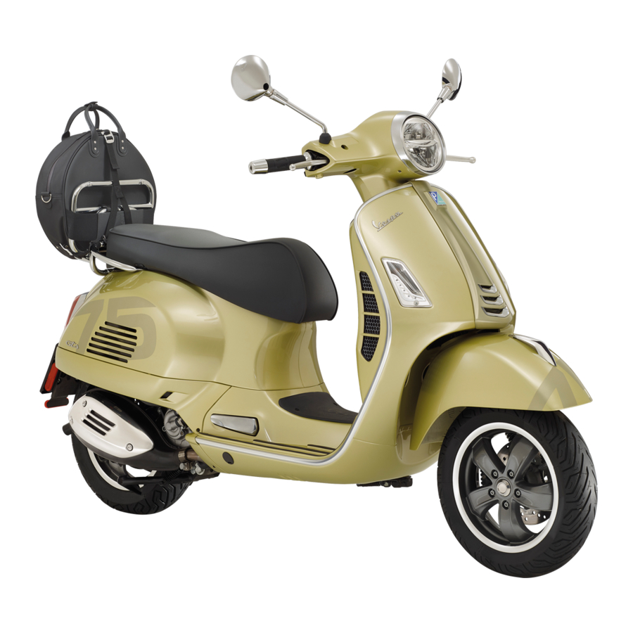
Page 124: Luggage Rack
Luggage rack (07_01, 07_02, 07_03) The "GTS Super" and "GTS SuperSport" versions are equipped with a grab handle "1", as shown in the photo. 07_01 The "GTS" and "GTS Touring" versions are equipped with rear luggage carriers "2", as shown in the photo. During use of the vehicle without a load on the rear luggage carriers, it is recommen- ded to position the retainer hook «A»... - Page 127 TABLE OF CONTENTS Switch: 40, 41 ABS: 43 Fuses: 90 Maintenance: 75, 119 Air filter: 84 Mirrors: 99 Technical Data: 109 Top box: 57 Horn: 41 Transmission: 72 Battery: 87, 88 Hub oil: 79 Puncture: 101 Turn indicators: 98 Brake: 86, 100 Tyres: 81 Identification: 58 Recommended products:...
- Page 128 The descriptions and images in this publication are given for illustrative purposes only. While the basic features as described and illustrated in this manual remain unchanged, Piaggio & C. S.p.A. reserves the right, at any time and without being required to update this publication beforehand, to make any changes to components, parts or accessory supplies which it deems necessary to improve the product, or which are required for manufacturing or commercial reasons.
Need help?
Do you have a question about the GTS Supertech 300 hpe and is the answer not in the manual?
Questions and answers