
Related Manuals for Polytec PSV-500-3D


Summary of Contents for Polytec PSV-500-3D
- Page 1 Title Operating Instructions Polytec Scanning Vibrometer P S V- 5 0 0 - 3 D Front-End PSV-F-500-3D-M Scanning Heads PSV-I-500/PSV-I-520 PSV-I-560/PSV-I-570 Junction Box PSV-E-500 PSV-W-500-M For the PSV-500-3D-M System...
- Page 2 Warranty and Service The warranty for this equipment complies with the regulations in our general terms and conditions in their respective valid version. This is conditional on the equipment being used as intended and as described in this operating instructions. The warranty does not apply to damage caused by incorrect usage, external mechanical influences or by not keeping to the operating conditions.
-
Page 3: Table Of Contents
Contents Contents 1 Safety Information 1.1 Information on Using these Operating Instructions ............. 1-1 1.1.1 Warning Notices Used ....................1-1 1.1.2 Notices Used ......................1-1 1.2 General Safety Information ....................1-2 1.2.1 Operating the Instrument Safely ................1-2 1.2.2 Intended Use ......................1-2 1.2.3 User Qualification ..................... - Page 4 6.3 No Measurement Signal or Implausible Measurement Signals ..........6-4 7 Technical Specifications 7.1 Harmonized Standards Applied ..................7-1 7.2 Front-End ...........................7-1 7.2.1 General Data ......................7-1 7.2.2 Signal Inputs and Outputs ..................7-2 7.2.3 Metrological Properties (PSV-500-3D Standard) ............7-3 7.2.4 Metrological Properties (PSV-500-3D Xtra) ...............7-8 7.2.5 Data Acquisition ......................7-13...
- Page 5 Contents 7.3 Junction Box ........................7-13 7.4 PC ........................... 7-14 7.4.1 General Data ......................7-14 7.4.2 PC Configuration ....................7-14 7.5 Scanning Heads ......................7-15 7.5.1 General Data PSV-I-5xx ..................7-15 7.5.2 General Data PSV-I-500/PSV-I-520 (Standard) ............7-17 7.5.3 General Data PSV-I-560/PSV-I-570 (Xtra) .............. 7-17 7.5.4 Optics PSV-I-500/PSV-I-520 (Standard) ..............
-
Page 6: Safety Information
1 Safety Information 1 Safety Information Information on Using these Operating Instructions These operating instructions are part of the product. Keep them within • easy reach. Read these operating instructions carefully before operating the • instrument. Pay attention to any documentation provided by other manufacturers. -
Page 7: General Safety Information
Any use other than the one described in this operating instructions is not permitted. Polytec rejects any liability for damages which occur from improper use. The instruments are designed in accordance with good engineering practice to meet state-of-the-art safety requirements, have been tested, and left the factory in a condition in which they are safe to operate. -
Page 8: Cleaning
Off-system hardware or software components could damage the system or impair the function of the software. This also applies for the change of hardware drivers which were not provided by Polytec and the change of configurations of the driver options. -
Page 9: Laser Safety
1 Safety Information Laser Safety 1.3.1 Important Warning Notices WARNING! Damage to eyes caused by incorrect usage of laser radiation! » Do not look directly into the laser beam. » Do not use mirrors or other optical instruments to look into the laser beam. »... -
Page 10: Warning Labels Affixed On The Instrument
1 Safety Information 1.3.2 Warning Labels Affixed on the Instrument Warning labels The laser warning labels are shown in the following figure. For countries in the PSV-500 European Union (EU), labels [2] and [3] are affixed in the language spoken in Standard the customer's country (see right-hand-side). - Page 11 1 Safety Information Warning labels The laser warning labels are shown in the following figure. For countries in the PSV-500 Xtra European Union (EU), labels [2] and [3] are affixed in the language spoken in the customer's country (see right-hand-side). Visible and Invisible Laser Radiation Sichtbare und unsichtbare Do not stare into beam...
-
Page 12: Applicable Standards And Directives
Laser Notice no. 50, dated 24 June 2007. CDRH Compliance Statement Polytec GmbH confirms that its laser products are certified to be fully compliant with all applicable standards and regulations as set forth by the United States of America's Health and Human Services (HHS), Food and Drug Administration (FDA), Center for Devices and Radiological Health (CDRH) pursuant to 21 CFR 1040.10 for laser products. -
Page 13: Information On Laser Class 2 For Psv-500 Xtra
1 Safety Information 1.3.5 Information on Laser Class 2 for PSV-500 Xtra The properties of laser light are different from those of conventional light sources. Due to the low divergence, laser light is generally extremely intense. When handling lasers, always take great care to make sure that the direct or reflected beam of the lasers do not enter anyone's eyes. -
Page 14: Equipment For Psv-500 Standard
1 Safety Information 1.3.6 Equipment for PSV-500 Standard Safety You can switch on or off the laser with the key switch on the front-end. • equipment You can switch on or off the laser using the software. • The geometry laser has to be switched on additionally via the software. •... -
Page 15: Electrical Safety
The instrument is subjected to EU directive 2014/30/EU (EMC directive) and therefore conforms with the limits for emission and immunity specified in the standards this is based on. With the CE mark Polytec confirms that the instrument has been tested successfully. -
Page 16: Introduction
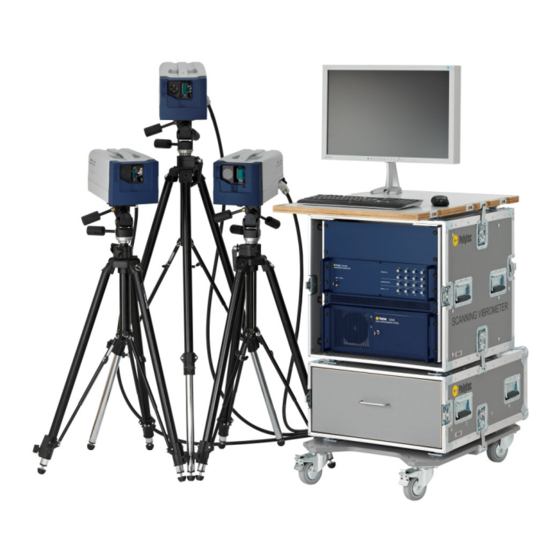
2 Introduction 2 Introduction Area of Application and System Summary The Polytec Scanning Vibrometer PSV measures the three orthogonal components of vibrational velocity on the basis of laser interferometry. The system components are shown in the following figure. Figure 2.1:... -
Page 17: Signal Flow Between The System Components
Front-end Doppler Doppler Vibrometer, signals signals Vibrometer signals Reference ecoder Control signal Control signals Control signals Generator Reference signals Reference connections Generator signals Generator connections Camera signal Camera signal Figure 2.2: Schematic diagram of the signal flow in the PSV-500-3D... -
Page 18: Decoders
2 Introduction 2.2.2 Decoders Only digital velocity decoders are used in the PSV-500-3D. This enables very precise and high-resolution acquisition of vibrations. With the H system the decoder signals are directly transmitted digitally to the PC. With the M system the signals are converted into analog signals and transmitted to the data acquisition board of the PC. - Page 19 2 Introduction...
-
Page 20: First Steps
3 First Steps 3 First Steps INFORMATION The components marked with an (*) are described in detail in separate operating instructions. Always pay attention to these operating instructions, too! Unpacking and Inspection ATTENTION! Misalignment of the optics by shock! The optics of the scanning head is highly sensitive. Its optics can get misaligned by shocks or vibrations. -
Page 21: Control Elements, Displays And Connections
3. In the case of a wrong delivery, damage or missing parts, immediately inform your local Polytec representative, stating the serial numbers of the instruments. The serial number can be found on the name plate. You will find the name plate on the instruments as well as on the inside cover of these operating instructions. - Page 22 3 First Steps POWER L is lit up: ready to operate (key switch in position I) IEPE 1 L is lit up: IEPE power supply for the REF 1 reference input activated in the software IEPE 2 and IEPE 3 L s are lit up: IEPE power supply for the corresponding reference input (REF 2 and REF 3) activated in the software (not for PSV-3D) REF 1 analog input (BNC jack)
- Page 23 3 First Steps Back view The back view of the front-end is shown in the following figure. Manufactured by: CONTROL GmbH D-76337 Waldbronn, Germany Model No.: PSV-500 Version: x xx xxxx Serial No.: yyyy Mfg.-Date: Mains: 100...240V 50/60Hz Fuses: x.x AT Power cons.: max xxxVA WARNING !
-
Page 24: Psv-E-500 Junction Box
3 First Steps 3.2.2 PSV-E-500 Junction Box Back view The back view of the junction box is shown in the following figure. Manufactured by: LEFT RIGHT FRONT-END GmbH D-76337 Waldbronn, Germany Model : PSV-E-500 PSV-500 Version: x xx xxxx Serial No.: JUNCTION BOX yyyy Mfg.-Date:... - Page 25 3 First Steps 3.2.3 Front view The front view of the PC is shown in the following figure. The lockable front flap is shown as transparent. RESET DATA MANAGEMENT SYSTEM POWER Figure 3.4: Front view of the PC Cooling fan Power L green: ready to operate HDD L...
- Page 26 3 First Steps Back view The back view of the PC is shown in the following figure. The order of the plug-in boards may vary from that shown in the figure. NETWORK WLAN MOUSE KEYBOARD 18 17 Figure 3.5: Back view of the PC Cooling fan Name plate Plate with information on model, serial number, power specifications, etc.
- Page 27 3 First Steps 11 VIDEO network connection (blue background) Connection for the blue network cable from the front-end/from the junction box to transmit the video signal of the video camera in the scanning head 12 USB interfaces (Universal Serial Bus, type A) Alternative connections for peripheral devices such as mouse, keyboard, etc.
-
Page 28: Scanning Head
3 First Steps 3.2.4 Scanning Head Front view The front view of the scanning head is shown in the following figure. Figure 3.7: Front view of the scanning head Mounting thread for the protective window or for the close-up unit (only PSV-1D) Front lens of the video camera with M37 mounting thread for the filter (only Standard) and lenses (only PSV-1D) Laser beam aperture... - Page 29 3 First Steps Back view The back view of the scanning head is shown in the following figure. LASER SIGNAL 10-32 OPTION UNF-2B Figure 3.8: Back view of the scanning head Transport handle SIGNAL level display Measure for the light scattered back from the measurement surface. The signal level display is deactivated when the geometry laser (Geo-Laser) is activated.
- Page 30 3 First Steps Bottom view The bottom view of the scanning head is shown in the following figure. Figure 3.9: Bottom view of the scanning head M6 mounting threads For the mounting or adapter plate, e.g. for mounting on a tripod system Mounting threads for quick release plate For fluid head, for example for assembly on the tripod Warning label...
-
Page 31: Assembly
Check the devices for external damages such as scratches or the like. In the case of a wrong delivery, damage or missing parts, please inform your local Polytec representative immediately, stating the serial number of the devices. -
Page 32: Scanning Heads
3 First Steps 3.3.1 Scanning Heads The scanning heads are mounted on VIB-A-T02 light duty tripods using fluid heads as shown in the following figure. Figure 3.10: Scanning head mounted on the light duty tripod with fluid head Position the scanning heads approximately in the shape of an equilateral triangle. -
Page 33: Vib-A-T02 Light Duty Tripod With Fluid Head
3 First Steps ATTENTION! Damage of the scanning head caused by too high ambient temperature! If the ambient temperature exceeds 35 °C (95 °F), the scanning head may overheat. This could damage it. » At ambient temperatures above 35 °C (95 °F) you must assemble the scanning head on a tripod (e.g. -
Page 34: System Cabinet
3 First Steps 4. A suitable hexagonal quick release plate has been pre-assembled on the scanning head. Use the quick release plate to position the scanning head on the fluid head. The safety lever clicks into place automatically. 3.3.3 System Cabinet Unpacking The system cabinet is supplied with all system components assembled and cabled. - Page 35 3 First Steps 10. Release the locking brakes and move the system cabinet down the ramp to the desired location. Build up Build up the system cabinet. To do so, proceed as follows: ATTENTION! Damage to the instruments caused by crushed cables! »...
- Page 36 3 First Steps Shift the To have more legroom when working on the system, you can shift the work workplate plate up to 12 cm forwards. To do so, proceed as follows: CAUTION! Risk of tilting caused by mishandling! When folded out the screen loads the workplate one-sided and the work plate can tilt.
- Page 37 3 First Steps Figure 3.14: Screen rotated by 90° 3. Tilt the screen forward until it lays flat on the foam. Figure 3.15: Screen tilted forward Figure 3.16: Screen completely folded in 3-18...
-
Page 38: Cabling
» Do not use any force when plugging in the cables. » If necessary, replace defective cables with new cables. » Contact your local Polytec representative. INFORMATION The main cable (umbilical) has a plug with a fixed (straight) cable connection and a connector with a rotatable (slightly angled) cable connection. -
Page 39: Connecting The Hardware
3 First Steps 3.4.1 Connecting the Hardware Front-end to PC 1. Plug the yellow network cable into the network connection on CONTROL the back of the front-end and into the network connection on CONTROL the back of the PC. 2. Plug the generator cable into the Sub-D connection on the GENERATOR IN back of the front-end and into the corresponding... - Page 40 3 First Steps JUNCTION BOX PSV-E-500 Manufactured by: LEFT RIGHT FRONT-END GmbH D-76337 Waldbronn, Germany Model : PSV-E-500 PSV-500 Version: x xx xxxx Serial No.: JUNCTION BOX yyyy Mfg.-Date: Mains: 100...240V 50/60Hz Fuses: 2.0 AT Power cons.: max. 100 VA WARNING ! Disconnect Mains before opening...
- Page 41 3 First Steps SCANNING HEAD TOP PSV-I-500 LASER SIGNAL SCANNING HEAD LEFT PSV-I-520 OPTION SCANNING HEAD RIGHT PSV-I-520 JUNCTION BOX PSV-E-500 Manufactured by: LEFT RIGHT FRONT-END GmbH D-76337 Waldbronn, Germany Model : PSV-E-500 PSV-500 Version: Serial No.: x xx xxxx Mfg.-Date: yyyy JUNCTION BOX...
- Page 42 10-32 UNF-2B 14. Screw the vibration sensor on the isolation stud. 15. Connect up the vibration sensor to a BNC jack on the front of the front-end. Polytec PSV-500 SCANNING HEAD LASER SIGNAL 10-32...
-
Page 43: Connecting The Signals
3 First Steps 3.4.2 Connecting the Signals Reference 1. Connect up the reference signal to the BNC jack on the front of the REF 1 signal front-end. External trigger 2. If required, connect the external trigger signal to the BNC jack on TRIG IN the front of the front-end. -
Page 44: Functional Test
The implementation of a first functional test is described in the following. If the instrument does not perform as described, read through the information on troubleshooting in C 6 and if required, contact your local Polytec HAPTER representative. For an initial functional test, proceed as follows: Prepare 1. - Page 45 3 First Steps Direction The following direction convention applies to the output signals: convention A movement towards the scanning head is seen as being positive. In this case the velocity output provides a positive signal. 3-26...
-
Page 46: Measuring
4 Measuring 4 Measuring Data acquisition and storage is controlled via the software. A live video image of the object is displayed on the monitor and you can define scan points directly on this live video image. You set all acquisition properties in the software. -
Page 47: Selecting Suitable Settings
4 Measuring Selecting Suitable Settings 4.2.1 Frequency Range With the PSV-3D, the accuracy of the in-plane vibration measurement depends on the following parameters: Accuracy of the laser beam overlap • Local wavelength of the vibration • The accuracy of the laser beam overlap should be at least one order of magnitude better than the local wavelength of the vibration. -
Page 48: Tracking Filter
4 Measuring 4.2.3 Tracking Filter Function The tracking filter can be used to improve the signal-to-noise ratio of the signal from the scanning head. This filter bridges brief dropouts. These dropouts occur due to the speckle nature of the light scattered back from the object. - Page 49 4 Measuring Selection For the tracking filter settings, you may use the following rules of thumb: Use the tracking filter to improve the signal-to-noise ratio if the optical • signal is weak. If you have a good optical signal, it is not possible for the tracking filter to improve the signal-to-noise ratio for physical reasons.
-
Page 50: Setting Up Optimal Stand-Off Distance (Only For Psv-500 Standard)
4 Measuring Setting Up Optimal Stand-Off Distance (Only for PSV-500 Standard) 4.3.1 Relation between Stand-Off Distance and Visibility Maximum INFORMATION With PSV-500 Xtra there are no visibility minima and therefore no periodic fluctuations of the signal level depending on the stand-off distance. Visibility The signal-to-noise ratio (SNR) of the data is primarily determined by the maxima... -
Page 51: Optimal Stand-Off Distances
OPTION ... + 204 Stand-off distance in mm Two laser modes with equal intensity Two laser modes with different intensity A strongly dominant laser mode Laser beam Polytec PSV-500 SCANNING HEAD Stand-off distance Object Figure 4.2: Measuring the stand-off distance 4.3.2... -
Page 52: Optimal Stand-Off Distances With Psv-A-560 Coherenceoptimizer
If the three laser beams are optimally aligned at a measurement point, then depending on the laser mode states, it is possible there may be some crosstalk between the three vibrometers. With the PSV-500-3D, the laser stabilization operating points are set so that this crosstalk is prevented. In the software, the state of the CoherenceOptimizer is displayed as being stable once all three scanning heads have stabilized. -
Page 53: Psv-G-500 Geometry Scan Unit
4 Measuring PSV-G-500 Geometry Scan Unit 4.4.1 Introduction The geometry scan unit is in the scanning head. It helps you to determine the distance to the object under investigation. If you make a geometry scan, within a few milliseconds the system switches from the vibrometer laser to the geometry laser and determines the exact distance to the object. -
Page 54: Functional Test
S 4.1, ECTION 4.2, S 4.3, and in your software manual. ECTION ECTION If your system does not perform as described above, read through the information on troubleshooting provided in C 6 and contact your local HAPTER Polytec representative. - Page 55 4 Measuring 4-10...
-
Page 56: Operating The Psv
5 Operating the PSV 5 Operating the PSV In the software manual, you will find the following detailed information on how to control the system via the software: Setting the optics • Aligning coordinates • Defining and editing scan points •... -
Page 57: Setting Up The Scanning Head
5 Operating the PSV Indicating Laser Activity Each scanning head is equipped with a which indicates laser LASER activity. The is on the back of the scanning head. LASER is lit when the laser is switched on (key switch on the front LASER •... -
Page 58: Troubleshooting
Exchanging or retrospectively installing subassemblies may only be carried out by authorized service personnel of Polytec. If faults or malfunctions cannot be solved by the measures described here or if faults / malfunctions occur which are not mentioned here, please contact our service department. -
Page 59: General Tests
In case of a malfunction, first check the following: 1. Have you connected up the system correctly as described in S 3.4? ECTION Front-end 2. Have you used the original network cables from Polytec? 3. Have you connected up correctly the network VIDEO CONTROL cables? 4. -
Page 60: Problems With The Laser
If the generator board is not displayed yet, check whether the board is properly inserted into its slot in the PC. If the generator board still does not appear, then contact the service department of Polytec. Problems with the Laser 6.2.1... -
Page 61: Highly Fluctuating Signal Level Display (Only Psv-500 Standard)
6 Troubleshooting 6.2.2 Highly Fluctuating Signal Level Display (Only PSV-500 Standard) If the signal level display on the back of the scanning head or in the software periodically fluctuates highly, proceed as follows: 1. Wait until the CoherenceOptimizer state is shown as being stable in the software. - Page 62 6 Troubleshooting INFORMATION In the column, the boxes for the Vibrometer Top, Vibrometer Left Vibrometer Right channels must not be ticked. You can now check the function of each of the scanning heads independently of each other. 9. Put a matt white test surface such as a piece of paper approximately 50 cm away from the front panel of the scanning head in the beam path.
- Page 63 6 Troubleshooting...
-
Page 64: Technical Specifications
7 Technical Specifications 7 Technical Specifications Harmonized Standards Applied Laser safety: IEC/EN 60825-1:2008-05 (Safety of Laser Products, complies to US 21 CFR 1040.10 and 1040.11 except for deviations pursuant to Laser Notice no. 50, dated 24 June 2007) Electrical safety: IEC/EN 61010-1:2011-07 (Safety requirements for electrical equipment for measurement, control, and laboratory use) -
Page 65: Signal Inputs And Outputs
7 Technical Specifications Calibration Recommended calibration interval: 2 years 7.2.2 Signal Inputs and Outputs REF 1 to REF3 (PSV-3D only REF 1) Input voltage range: ± 200 mV … ± 10 V Input impedance: 1 MΩ, in parallel with 100 pF Input coupling: AC / DC, adjustable in the software AC –... -
Page 66: Metrological Properties (Psv-500-3D Standard)
0.4 V (I = 2 mA) 7.2.3 Metrological Properties (PSV-500-3D Standard) DV-04 Digital Velocity Decoder Table 7.1: Metrological properties of the DV-04 decoder for PSV-500-3D Standard (1 of 5) Full scale value (peak) mm/s Scaling of analog output 0.25 1.25 Frequency range Max. - Page 67 7 Technical Specifications Table 7.2: Metrological properties of the DV-04 decoder for PSV-500-3D Standard (2 of 5) Full scale value (peak) mm/s Scaling of analog output 12.5 Frequency range Max. acceleration 2 560 16 000 Frequency response 0.0 Hz…100 kHz ±0.1...
- Page 68 7 Technical Specifications Table 7.3: Metrological properties of the DV-04 decoder for PSV-500-3D Standard (3 of 5) Full scale value (peak) mm/s Scaling of analog output Frequency range 1 000 2 000 2 000 Max. acceleration 64 000 256 000...
- Page 69 7 Technical Specifications Table 7.4: Metrological properties of the DV-04 decoder for PSV-500-3D Standard (4 of 5) Full scale value (peak) 1 000 2 000 5 000 mm/s Scaling of analog output 1 250 Frequency range 2 000 2 000 2 000 Max.
- Page 70 7 Technical Specifications Table 7.5: Metrological properties of the DV-04 decoder for PSV-500-3D Standard (5 of 5) Full scale value (peak) 10 000 12 000 mm/s Scaling of analog output 2 500 3 000 Frequency range 2 000 Max. acceleration...
-
Page 71: Metrological Properties (Psv-500-3D Xtra)
7 Technical Specifications 7.2.4 Metrological Properties (PSV-500-3D Xtra) Table 7.6: Metrological properties of the DV-04 decoder for PSV-500-3D Xtra (1 of 5) Full scale value (peak) 12.5 mm/s Scaling of analog output 0.612 1.22 3.06 Frequency range Max. acceleration ±0.1 ±0.1... - Page 72 7 Technical Specifications Table 7.7: Metrological properties of the DV-04 decoder for PSV-500-3D Xtra (2 of 5) Full scale value (peak) mm/s Scaling of analog output 6.12 12.2 30.6 Frequency range Max. acceleration 1 600 6 400 40 000 Frequency response 0.0 Hz…100 kHz...
- Page 73 7 Technical Specifications Table 7.8: Metrological properties of the DV-04 decoder for PSV-500-3D Xtra (3 of 5) Full scale value (peak) 1 250 mm/s Scaling of analog output 61.2 Frequency range 1 000 2 000 2 000 Max. acceleration 160 000...
- Page 74 7 Technical Specifications Table 7.9: Metrological properties of the DV-04 decoder for PSV-500-3D Xtra (4 of 5) Full scale value (peak) 2 500 5 000 12 500 mm/s Scaling of analog output 1 225 3 062 Frequency range 2 000...
- Page 75 7 Technical Specifications Table 7.10: Metrological properties of the DV-04 decoder for PSV-500-3D Xtra (5 of 5) Full scale value (peak) 25 000 30 000 mm/s Scaling of analog output 6 124 7 349 Frequency range 2 000 Max. acceleration...
-
Page 76: Data Acquisition
7 Technical Specifications 7.2.5 Data Acquisition Components/Properties PSV-500-3D-M Data acquisition PCI-6110 Reference channel Maximum bandwidth 1 MHz (2 MHz) Function generator M2i.6030 Output channel Maximum bandwidth 1 MHz (2 MHz) The specifications in brackets are available as an option. Junction Box... -
Page 77: General Data
7 Technical Specifications 7.4.1 General Data Mains Connection Mains voltage: 100…240 VAC ± 10%, 50/60 Hz Power consumption: max. 525 VA Protection class: 1 (protective grounding) Ambient Conditions Operating temperature: +5 °C…+40 °C (41 °F … 104 °F) Storage temperature: -10 °C…+65 °C (14 °F …... -
Page 78: Scanning Heads
7 Technical Specifications Scanning Heads 7.5.1 General Data PSV-I-5xx Ambient Conditions ATTENTION! Damage of the scanning head caused by too high ambient temperature! If the ambient temperature exceeds 35 °C (95 °F), the scanning head may overheat. This could damage it. »... - Page 79 7 Technical Specifications Dimensions Ø4 Ø4 Figure 7.1: Dimensions of the scanning head (Dimensions not specified are given in mm.) 7-16...
-
Page 80: General Data Psv-I-500/Psv-I-520 (Standard)
7 Technical Specifications 7.5.2 General Data PSV-I-500/PSV-I-520 (Standard) Laser Laser type: Helium-neon Wavelength: 633 nm Cavity length: 204 mm ±1 mm Laser class: Emitted laser power: < 1 mW Electrical Data Power consumption: approx. 45 W (average value) Carrier frequency: 40 MHz Housing Protection rating:... -
Page 81: Optics Psv-I-500/Psv-I-520 (Standard)
7 Technical Specifications Housing Protection rating: IP10 (according to EN 60529) IP40 (beam shutter closed or PSV-A-526 protective window mounted) Dimensions: refer to F IGURE Weight: approx. 9.5 kg (including geometry scan unit) 7.5.4 Optics PSV-I-500/PSV-I-520 (Standard) Focal length (nominal): 70 mm Minimum stand-off distance: 125 mm... - Page 82 7 Technical Specifications Signal Level Depending on Surface and Stand-off Distance Retro-reflective film Diffuse white surface Stand-off distance [m] Figure 7.3: Typical signal level range depending on the stand-off distance measured on a diffuse white surface and 3M Scotchlite™ Tape (retro-reflective film) Table of the Visibility Maxima Visibility maxima (mm) for l = 204 mm 1161...
-
Page 83: Optics Psv-I-560/Psv-I-570 (Xtra)
Measured from the front of the scanning head For 3 dB signal reduction At the front of the scanning head 0.01 1E-3 1E-4 Distance from front panel [m] Figure 7.4: Depth of focus subject to the stand-off distance (PSV-500-3D Standard) 7-20... -
Page 84: Scanner Psv-I-5Xx
7 Technical Specifications Signal Level Depending on Surface and Stand-off Distance Retro-reflective film Diffuse white surface Stand-off distance [m] Figure 7.5: Typical signal level range depending on the stand-off distance measured on a diffuse white surface and 3M Scotchlite™ Tape (retro-reflective film) 7.5.6 Scanner PSV-I-5xx Type:... -
Page 85: Geometry Scan Unit (Only Psv-I-500/Psv-I-560)
7 Technical Specifications 7.5.8 Geometry Scan Unit (Only PSV-I-500/PSV-I-560) Laser Laser type: Laser diode Wavelength: 670 nm ± 5 nm Laser class: Laser power: < 1 mW Accuracy of the distance typ. ±2,5 mm, depends on the signal level, for stand- measurement: off distances ≥1,5 m System Cabinet... -
Page 86: Appendix A: Optional Accessories
A Optional Accessories Appendix A: Optional Accessories A.1 PSV-A-430 Acoustic Gate Unit With the acoustic gate unit you can start or stop a measurement depending on a characteristic noise (e.g. start measuring with brakes squealing). Connect up the acoustic gate unit using a BNC cable to the jack on the AUX IN front of the front-end. - Page 87 A Optional Accessories A.2.2 Control Elements of the Video Camera with Standard Lens Back view The back view of the video camera with standard lens is shown in the following figure. Figure A.1: Back view of the video camera IEEE interface Connection for the IEEE-1394 cable (FireWire®) to the PC to transmit the video signal, for mains supply and to control of the video camera.
- Page 88 A Optional Accessories A.2.3 Control Elements of the Video Camera with Zoom Lens Back view The back view of the video camera with zoom lens is shown in the following figure. Figure A.3: Back view of the video camera IEEE interface Connection for the IEEE-1394 cable (FireWire®) to the PC to transmit the video signal, for mains supply and to control of the video camera.
- Page 89 A Optional Accessories Zooming ring Ring for manual setting of the focal length Focusing ring Ring for manual focusing Close-up lens and front lens Close-up lens for stand-off distances from 180 to 300 mm (refer also to A.2.5.2) ECTION PSV-A-445 helium-neon block filter The filter reduces the intensity of the laser light scattered back to the video camera by 98%.
- Page 90 A Optional Accessories Figure A.5: Assembly of the tripod adapter angle 6. Remove the quick release plate from the geared head by simultaneously pressing the safety knob on the bottom side and moving the safety lever counterclockwise to the end position. 7.
- Page 91 A Optional Accessories A.2.5 Technical Specifications A.2.5.1 General Data Power Supply Supply voltage: 8 V … 36 VDC (via the IEEE-1394 interface) Power consumption: max. 2.5 W (@ 12 VDC) Ambient Conditions Operating temperature: +5 °C…+40 °C (41 °F…104 °F) Storage temperature: −10°...
- Page 92 A Optional Accessories Zoom Lens Lens: F 2.5/f = 8.5 ... 90 mm, (zoom, focus, iris; manually adjustable) Angle of view (horizontal): @ wide end: approx. 28° @ tele end: approx. 2.8° Stand-off distance with close- up lens: approx. 180 mm … 300 mm Stand-off distance without close-up lens: approx.
- Page 93 A Optional Accessories INFORMATION Soiling on the protective window will taint the measurement results. Thus the protective window has to be free of dirt and dust. Remove dust only with compressed air from an air duster. Remove dirt with a lint-free cellulose cloth and only use water-based or alcohol-based glass cleaner if necessary.
- Page 94 A Optional Accessories Figure A.7: Assembly of the protective window A.4.3 Technical Specifications Dimensions (w x h x d): 145 mm x 107 mm x 22 mm Weight: 0.285 kg (without plastic plate and protective cover) Max. scanning angle in y-direction:± 15° Max.
- Page 95 A Optional Accessories Figure A.8: Front view (on the left) and back view (on the right) of the reference object A.6 EXT External Scanner Control By default, in the scanning head the DAC output signals are connected directly to the control inputs of the scanners. If the scanning head is provided with the EXT option (external scanner control), the DAC output signals and the control inputs of the scanners are available at the OPTION jack.
- Page 96 A Optional Accessories 8-Pin DIN Circular Plug Socket type: 8-Pin DIN Circular Plug Manufacturer: Amphenol-Tuchel Series: C 091 D Figure A.9: Pin configuration of the 8-pin DIN circular plug (view: solder side) Signal Function DAC GND Y Reference potential, DAC output Y DAC GND X Reference potential, DAC output X DAC OUT X...
- Page 97 A Optional Accessories A-12...
-
Page 98: Appendix B: Basics Of The Measurement Procedure
B Basics of the Measurement Procedure Appendix B: Basics of the Measurement Procedure B.1 Theory of Interferometric Velocity and Displacement Acquisition Optical interference can be observed when two coherent light beams are made to coincide. The resulting intensity fluctuation, e.g. on a photodetector, varies with the phase difference φ... - Page 99 Interferometers of this type which are directionally sensitive are described as heterodyne. B.2 Optical Configuration in the Scanning Head In vibrometers from Polytec, velocity and displacement acquisition are carried out using a modified Mach-Zehnder interferometer. The optical configuration in the scanning head is shown schematically in the following figure.
-
Page 100: Appendix C: Declaration Of Conformity
C Declaration of Conformity Appendix C: Declaration of Conformity Figure C.1: Declaration of conformity for the PSV-500-3D... - Page 101 C Declaration of Conformity...
-
Page 102: Index
Index cabling acoustic gate unit external scanner control A-10 external trigger 3-24 function generator Numerics 3-24 main components 3-20 10-32 UNF-2B, connection on the scanning mains connection 3-24 head 3-10 reference signal 3-24 vibration sensor 3-23 calibration interval, recommended ACQUISITION CDRH Compliance Statement connection on PC cleaning... - Page 103 emission, EMC standards equipment label Laser (Standard) name plate (front-end) Laser (Xtra) name plate (scanning head) 3-10 PSV-W-500 PC 7-14 warning label for assembly (scanning EU countries, laser warning labels 1-5, 1-6 head) 3-11 labels laser warning labels (Standard) laser warning labels (Xtra) fitting holes for close-up unit, on the scanning name plate (junction box) head...
- Page 104 name plate connection on junction box jacks on the front-end on PC specifications on the front-end reference object on the scanning head relative humidity 3-10 notices front-end specifications electrical safety PC specifications 1-10 7-14 RIGHT, connection on junction box object laser Xtra, specifications safety equipment 7-17...
- Page 105 suitable settings video camera, external frequency range assembly measurement range cabling optimal stand-off distances control elements (standard lens) stand-off distance and visibility maximum control elements (zoom lens) stand-off distances with introduction CoherenceOptimizer specifications tracking filter switch off, PSV switch on, PSV warning label for assembly, on the scanning SYNC head...
- Page 106 Contact Polytec Europe Polytec Worldwide Germany (DE) ASEAN Countries Polytec GmbH Polytec South-East Asia Pte. Ltd. Ltd. Headquarters Blk 4010, Ang Mo Kio Ave 10 Polytec-Platz 1–7 #06-06 TechPlace I 76337 Waldbronn Singapore 569626 Tel.: +49 7243 604-0 Tel.: +65 64510886...
Need help?
Do you have a question about the PSV-500-3D and is the answer not in the manual?
Questions and answers