Table of Contents
Advertisement
Quick Links
Advertisement
Table of Contents

Related Manuals for Objet Eden500V


Summary of Contents for Objet Eden500V
- Page 1 User Guide English Eden500V/350V/350 3-D Printer System...
- Page 3 Copyright Copyright © 2008 Objet Geometries Ltd. All rights reserved. This documentation contains proprietary information of Objet Geometries Ltd. This information is supplied solely to assist authorized users of the Eden500V/350V/350 3‐D printing system. No part of this document may be used for other purposes, and it may not be disclosed to other parties. The specifications on which this document is based are subject to change without notice. No part of this book may be reproduced in any form or by any means, nor stored in a database or retrieval system, without prior permission in writing from Objet Geometries Ltd. If this document is distributed as a PDF file, you may print it for internal use. Trademarks ® ® The following are registered trademarks of Objet Geometries Ltd.: Objet , Fullcure The following are trademarks of Objet Geometries Ltd.: Eden, Eden500V, Eden350V, Eden350, Eden330, Eden260, Eden250, Connex, Connex500, PolyJet, PolyJet Matrix, PolyLog, Objet Studio, Job Manager, SHR, TangoBlack, TangoGray, TangoPlus, VeroBlue, VeroWhite, VeroBlack, Digital Materials. Microsoft and Microsoft XP are trademarks of Microsoft Corporation. All names of products and services cited in this book are trademarks or registered trademarks of their respective companies. FCC Compliance The 3‐D printing systems referred to in this guide have been tested and found to comply with the limits for a Class A device pursuant to part 15 of the FCC rules. These limits provide reasonable protection against harmful interference when the equipment is operated in a commercial environment. Objet 3‐D printing systems generate, use and can radiate radio frequency energy. If not installed and used in accordance with instructions in the relevan installation and user guides, these systems may cause harmful interference to radio communications. Operation of Objet 3‐D printing systems in residential areas may cause unacceptable interference to radio and TV reception, requiring the operator to take whatever steps are necessary to correct the interference. Equipment Recycling In the European Union, this symbol indicates that when the last user wishes to discard a product, it must be sent to appropriate facilities for recovery and recycling. For information about proper disposal, check your purchase contract, or contact the supplier of the equipment. ...
- Page 4 Patents This product is covered by one or more of the following U.S. patents: 5,263,130 5,287,435 5,386,500 5,519,816 5,695,708 6,259,962 6,569,373 6,644,763 6,658,314 6,850,334 6,863,859 7,183,335 7,209,797 7,225,045 7,300,619 Objet Geometries Ltd. http://www.2objet.com DOC‐00500 Rev. F January 2008 DOC-00500 Rev. F...
-
Page 5: Table Of Contents
Light ..............................3–5 Safety Considerations......................... 3–5 Disposal ..............................3–5 Work Environment ..........................3–5 Workstation Requirements....................... 3–6 Preparing Files for Use with Eden 3‐D Printing Systems ............3–6 Converting CAD Files to STL Format....................3–6 Converting Files to SLC Format ....................... 3–7 Objet Software ............................ 3–7 4 Installing Objet Software How to Install Software for the Eden 3‐D Printing System............4–2 5 Using Objet Studio Opening Objet Studio........................5–2 Toolbars ..............................5–2 Preparing Models for Production....................5–3 Opening STL & SLC Files ........................5–3 Copying and Pasting Objects ...................... - Page 6 Handling Completed Trays......................5–21 Tray Validation ..........................5–21 Object Color Codes..........................5–22 Quality/Speed Setting ........................5–22 Production Estimates ........................5–23 Saving the Tray File........................... 5–23 Printing the Tray File ........................5–23 Additional Objet Studio Features ....................5–24 Dividing Objects ..........................5–24 Choosing the Support Strength ...................... 5–24 Displaying the Cross Section of Objects..................5–25 Printing the Screen Display on Paper..................... 5–26 Saving the Screen Display as an Image File .................. 5–26 Exporting and Importing Objet Build Trays ................. 5–27 Advanced‐Mode Features ......................5–27 Save Tray As…...........................
- Page 7 User Guide Maintaining Eden 3‐D Printers ...................... 7–16 Routine Maintenance Schedule....................... 7–16 Cleaning the Print Heads......................... 7–16 Pattern Test ............................7–19 Improving Print Quality ........................7–20 Cleaning and Replacing the Wiper ....................7–20 Aligning the Print Heads ......................... 7–23 Replacing Print Heads........................7–27 Replacing the UV Lamps ......................... 7–37 Built‐in Tests ............................7–43 Replacing the Waste Container....................... 7–47 8 Handling Printed Models Removing Models After Printing ....................8–2 Removing the Support Material ...................... 8–2 Storing Models ...........................
-
Page 9: About This Guide
About This Guide Using This Guide................. 2 For More Information ................. 2 Terms Used in This Guide..............3 1–1 DOC-00500 Rev. F... -
Page 10: Using This Guide
About This Guide Using This Guide This user guide provides instructions for installing, operating and maintaining Eden 3‐D printing systems. It explains how to use features, and provides practical examples to guide you as you use the system. The text and figures in this guide are based on the Eden500V 3‐D printer, printer software version 50.0.1.14 and Objet Studio software version 8.0.2.3. This guide assumes that: • all the hardware, software, and network components of your Eden system are installed, configured, and operating correctly. ® • the operator has a working knowledge of the Windows PC platform. For More Information Visit http://www.2objet.com/ for more details about Objet’s technology, products and consumables, and for service and support contacts. For other documents that relate to Eden500V/Eden350V/Eden350 3‐D printing systems, and for this document in other languages, contact your regional Objet Customer Support office. If you have any questions about the information presented in this document, or if you have any comments or suggestions for future editions, please send a message to support@2objet.com. 1–2 DOC-00500 Rev. F... -
Page 11: Terms Used In This Guide
Eden500V/350V/350 User Guide Terms Used in This Guide build tray In Objet Studio: The surface displayed on the screen that represents the actual build tray in the Eden printer. In the Eden printer: The surface upon which models are produced. cleaning fluid Cleanser for flushing model feed tubes and the printing block, used to completely remove model material from the system before loading another type of material in the printer. The cleaning fluid is supplied in model‐material cartridges. client/user workstation The workstation on which Objet software is installed, used for preparing build trays for production on Eden printers. (There is no limit to the number of client workstations in the local network.) Eden™ printer The Eden500V/Eden350V/Eden350 3‐D printer referred to in this guide. Eden computer The computer inside the Eden printer that operates it. (This is sometimes referred to as the “embedded” computer.) Eden printer interface The GUI (graphical user interface) used for controlling the Eden printer. Eden software Software running on the computer inside the Eden printer that controls all printer operations. host/server workstation The workstation on which the full version of Job Manager is installed. This workstation interfaces directly with the Eden printer and is typically positioned next to it. Job Manager™... -
Page 13: Safety
Safety Safety Features..................2 Symbols and Warnings............... 3 Safety Guidelines................. 4 Eden Printer ................... 4 Model and Support Material ............... 5 First Aid for Working With Resins ........... 6 Waste Disposal..................7 2–1 DOC-00500 Rev. F... -
Page 14: Safety Features
Safety Safety Features Eden 3‐D printers are designed and manufactured to comply with CE and FCC standards. They are equipped with the following safety features: Cover lock The cover is locked while the printer is working. It is released when the printer reverts to pause or stop mode. WARNING: Do not defeat the safety lock. Doing so could result in serious personal injury. If the safety lock does not function correctly, contact your service provider. Cover interlock The internal AC power supply (to the UV lamp, switch motion motors and the tray heater) is turned off when the cover is opened. WARNING: Do not defeat the interlock switch. Doing so could result in serious personal injury. If the interlock does not function correctly, contact your service provider. UV screen The transparent section of the cover blocks harmful UV radiation, allowing the operator to view the model as it is being made. Circuit breaker The main power supply is turned off by an internal switch in case of an electrical malfunction. Grounded chassis The frame and chassis of the printer are grounded to prevent electrical shock. If the Eden 3-D printing system is not used as specified in this guide, the safety features may not provide adequate protection. -
Page 15: Symbols And Warnings
Eden500V/350V/350 User Guide Symbols and Warnings This following table lists the warning labels located on or in Eden printers. Warning Meaning Location Comments Symbol Hazard (general) The main label on Caution. the back of the printer. Hot surface Near head block. Risk of burns. Do not touch this surface when hot. High voltage Near UV lamp Risk of electric connectors, on shock. the rear, left and right covers of the UV enclosure. Ultraviolet Near UV lamps Risk of injury from radiation ultraviolet radiation. Always use protective eyewear during operation. Moving parts Near tray Risk of injury from ... -
Page 16: Safety Guidelines
Safety Safety Guidelines The following general guidelines, together with the instructions provided throughout this user guide, ensure user safety while operating and maintaining the Eden system. If the system is not operated as specified, the userʹs safety may be compromised. Eden Printer Installation and removal of the Eden printer should only be done by qualified service personnel. The Eden printer should only be operated by persons trained by an Objet customer‐support representative. Service operations should be performed only by personnel who have been instructed in relevant safety precautions. All personnel operating or maintaining the Eden printer should know the location of first aid and emergency equipment and how to use it. Never block access to this equipment. Never attempt to open the main cover of the printer while it is working. Never bypass the interlock safety switch. If the interlock safety switch ever fails, or if servicing is ever necessary while the main cover is open, never stare directly at the UV lamps without glasses that screen out UV radiation. For this purpose, ordinary sunglasses with UV screening are adequate. Never connect the power plug to a socket that does not have a ground (earth) wire, and never disconnect the ground. Doing so may expose the operator to serious danger from electric shock. The power cable should be connected at an easily accessible electric socket near the printer. Never insert screwdrivers, wires, or other objects into the power supply housing. Leave a minimum of 15 centimeters between ventilation openings and walls or other objects. Several parts of the printer remain extremely hot even after it has stopped operating. Avoid touching the main power supply, the UV‐ lamp power supply, UV lamps, and the print heads. Notify co‐workers and those who have access to the Eden system before beginning non‐routine and hazardous work. Report any potential dangers and safety‐related accidents to your safety officer or to other appropriate authorities. -
Page 17: Model And Support Material
Eden500V/350V/350 User Guide Model and Model and support materials are made of resins. Although precautions Support must be taken when handling resins directly, all model and support Material materials used by the Eden system are handled in sealed cartridges. Normally, operators of the Eden printer should never be directly exposed to dangerous materials. Most of the following recommendations for handling resins apply to the unlikely event of a leak or spill. If this should occur, follow the specific instructions printed on the printing‐material cartridge used. Store cartridges of model and support materials indoors, in a dry area with adequate ventilation, between 16‐27 degrees Celsius (60‐81 degrees Fahrenheit). Never expose them to flames, heat, sparks, or direct sunlight. Keep model and support materials away from areas where food and drink are stored, prepared and consumed. Uncured resin is considered a hazardous material, requiring certain precautions when handling it. To prevent skin irritation, wear protective gloves, if necessary. If there is any chance that model and support materials might splash into the eyes, wear safety goggles. Prolonged direct contact with resins can cause an allergic reaction. To prevent respiratory irritation, ventilate areas where model and support materials are used. The ventilation system should totally replace the air 20 times per hour. Clean model‐material and support‐material spills with disposable towels or other absorbent, non‐reusable material, such as sawdust or activated charcoal. Rinse the spill area with denatured or isopropyl alcohol (IPA), followed by soap and water. Dispose of the absorbent material in accordance with local regulations. Do not wash contaminated clothing at home; clothing should be professionally laundered. Dispose of contaminated shoes, belts and other leather items. Absorbed resin may re‐expose the user when these items are worn again. 2–5 DOC-00500 Rev. F... -
Page 18: First Aid For Working With Resins
Safety First Aid for Working With Resins In general, try to avoid direct contact with uncured resin. If skin or eyes come into contact with resin, wash the area immediately and thoroughly with water, and follow the first‐aid instructions below. Contact with If uncured resin comes in contact with skin, wash the affected area Skin immediately and thoroughly with soap and cool water, then remove contaminated clothing. Pay particular attention to flushing the hair, ears, nose and other parts of the body that are not easily cleaned. Use cool water to prevent skin pores from opening, so that the resin does not easily penetrate the skin. Do not use solvents to clean skin. If large areas of skin have been exposed to resin, or if prolonged contact results in blisters, seek medical attention. Avoid the accidental transfer of resin from the hands to other areas of the body, especially to the eyes. If protective cream was used, do not reapply it until the skin has been completely cleansed. Contact with If uncured resin comes in contact with the eyes, flush immediately with Eyes large amounts of water for 15 minutes and seek medical attention. Avoid sunlight, fluorescent light, and other sources of ultraviolet radiation. The wearing of contact lenses when working near resin is not recommended. If resin splashes into the eyes when contact lenses are worn, immediately remove the lenses and flush the eyes with water. Clean and disinfect the contaminated lenses. Do not wear contact lenses until eye irritation disappears. Ingestion If resin is swallowed, refer to the cartridge label for specific instructions. Seek medical attention immediately. -
Page 19: Waste Disposal
Eden500V/350V/350 User Guide Waste Disposal Fully cured resins present no special safety or health‐related issues. However, check if local regulations regard cured and partially cured resins as hazardous industrial waste, and comply with all applicable regulations governing their disposal. When removing the waste container from the Eden printer, protective gloves are not required. When directly handling uncured resins, neoprene or nitrile gloves should be worn. When handling cured materials that may not be completely cured on the surface, common latex gloves are adequate. Even if not classified as hazardous industrial waste or otherwise regulated, resin materials must be packaged and disposed of in a manner that prevents human contact with the waste. Therefore, take steps to prevent the contamination of both groundwater and surface water. Empty model‐material and support‐material cartridges are sealed to prevent leakage. Do not attempt to reuse them, and do not puncture them. Discard contaminated clothing, shoes, empty containers, etc., in accordance with any applicable laws and regulations. 2–7 DOC-00500 Rev. F... -
Page 21: Introducing The Eden 3-D Printing System
STL Files ....................4 SLC Files ....................4 Printing Materials................4 Storage ....................5 Shelf Life ....................5 Light ......................5 Safety Considerations ................5 Disposal ....................5 Work Environment................5 Workstation Requirements ..............6 Preparing Files for Use with Eden 3‐D Printing Systems....6 Converting CAD Files to STL Format ..........6 Converting Files to SLC Format............7 Objet Software..................7 3–1 DOC-00500 Rev. F... -
Page 22: Work Configurations
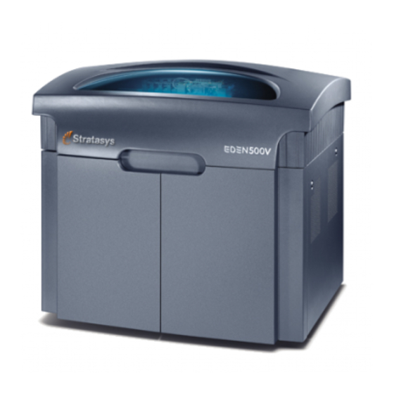
Introducing the Eden 3-D Printing System Eden500V/Eden350V/Eden350 Figure 3-1: The 3-D Printer Work Configurations The Eden 3‐D printing system can be set up as a single‐station system or as a multi‐station system. When connected to a local computer network, the system can serve multiple users. In such configurations, each user workstation (client) prepares files with Objet Studio software for production. A server (host), typically next to the 3‐D printer, acts as a job manager that sends production jobs to the printer for production. Figure 3‐2 shows the Eden printer set up in a multi‐client configuration. 3–2 DOC-00500 Rev. F... -
Page 23: Source Files
Eden500V/350V/350 User Guide Client workstations Eden server KVM switch Printer workstation Eden printer Figure 3-2: Multi-client network configuration When installing the Objet software, you choose whether to install it as a client station or as a master station (server or standalone station). The Objet software arranges the jobs it receives according to their priorities, model‐material type, and other factors. In multi‐workstation configurations, the operator of the server—typically the production administrator—has total control over the jobs sent to the 3‐D printer, and can prioritize and delete jobs, review job history and reprint a job, and so Source Files Eden 3‐D printing systems produce three‐dimensional models designed with most 3‐D CAD tools and with other job‐specific 3‐D applications. Eden systems accept: • STL files • SLC files Eden systems feature the capability of producing both types of model files simultaneously. 3–3 DOC-00500 Rev. F... -
Page 24: Stl Files
Most CAD software can export STL files. The Eden system utilizes these files for building models (rapid prototyping), and also for directly making molds for mass‐producing items. STL files are ASCII (text) files. The content of each file begins with “solid” and ends with “end‐solid” (both lower case). Between these keywords is a list of the triangles that describes the faces of the solid model. Each triangle defines a single normal vector directed away from the solid’s surface, followed by its X‐Y‐Z coordinates. These are expressed as Cartesian coordinates and are floating‐point values. The coordinates of all triangles should be positive and should fall within the volume of the model. SLC Files SLC is short for Stereo‐Lithography Contour. SLC files describe two‐ dimensional contours of the three‐dimensional models. These contour lines are polylines. SLC files are ASCII (text) files that save models as a series of slices. This means that models based on SLC files cannot be orientated; only their scale (size) and position on the build tray can be controlled. For this reason, the model’s orientation must be suitable for production before it is saved as an SLC file. Because of the nature of SLC files, the appearance of models in Objet Studio may be different than the solid‐object images displayed from STL files. Printing Materials Materials used for printing models with Eden printers are made of resins, which are composed of reactive monomers and oligomers. Care must be taken when storing and handling them, both to protect operators and the environment, and to ensure their effectiveness. Signs of premature polymerization in material cartridges may include bulging, leaking, the emission of heat, and unusual odor. Exposure to heat can cause resin to gel in the cartridge. To prevent this, observe the following guidelines when handling and storing Eden modeling and support materials. 3–4 DOC-00500 Rev. F... -
Page 25: Storage
Eden500V/350V/350 User Guide Storage Printing materials used with Eden systems are supplied in UV‐proof cartridges. • To ensure product stability, do not allow these materials to come into contact with metal. Plastics made from monomer‐soluble substances (such as polystyrene or polyvinyl chloride) are not suitable for storing Objet printing materials. • When not in use, keep material cartridges tightly sealed to prevent contamination, the effects of exposure to UV radiation, and accidental spillage. • Store material cartridges indoors, in a dry area with adequate ventilation, between 16–27 degrees Celsius (60–81 degrees Fahrenheit). If exposed to heat or flames, cartridges may burst or ignite. • Make sure that material cartridges are stored in accordance with all local regulations and other applicable requirements. Shelf Life Materials used for producing models have a limited shelf life. The expiry date on the label is valid when properly stored in an undamaged, unopened cartridge. Always rotate your stock, so that the cartridge with the earliest date is used first. Light If printing materials are not in their sealed cartridges, make sure to shield them from sunlight and other sources of UV radiation, such as fluorescent and mercury‐vapor lights. Exposure to UV radiation causes an increase in viscosity and, eventually, solidification. Safety Before being cured, resins are hazardous materials. To prevent possible Considerations health hazards, follow these precautions regarding printing materials: • Do not expose to flames, heat or sparks. •... -
Page 26: Workstation Requirements
Introducing the Eden 3-D Printing System Workstation Requirements The minimum requirements for computer components used with Objet 3‐D printer software are listed in the following table. Server/ Client Workstation Stand-alone Station Processor Pentium 4, 3.0 GHz, Pentium 4, 3.0 GHz (min.) 512 KB cache memory (min.) Operating System Microsoft Windows XP or Microsoft Windows XP or Windows 2000 Windows 2000 Graphics Card Supporting open GL, Supporting open GL, with 256 MB of memory with 256 MB of memory 2 GB (min.) 1 GB (min.) CD Drive IDE CD ROM IDE CD ROM Hard-Disk Drive 40 GB (min.) 40 GB (min.) -
Page 27: Converting Files To Slc Format
Eden500V/350V/350 User Guide 4. In the file format option, choose binary or ASCII. (Binary files are smaller than files saved in ASCII format; they are, however, functionally identical in Objet Studio.) 5. Click or Save Converting When converting files to SLC format, it is recommended that you set a layer Files to SLC thickness of 15 microns (0.015 mm). Since SLC files cannot be orientated in Format Objet Studio, it is important that models are properly orientated before being saved as SLC files. Considerations for suitable model orientation are explained in “Model Orientation” on page 5‐10. Objet Software Objet software for the Eden 3‐D printing system consists of two applications: • Objet Studio • Job Manager Objet Studio With Objet Studio, you prepare source files for production in Eden 3‐D printers. Objet Studio offers you a wide variety of file‐preparation options, but always consists of the following basic procedure: 1. Inserting one or more objects on the build tray 2. Positioning the object(s) on the tray 3. Configuring object and tray parameters 4. -
Page 29: Installing Objet Software
Installing Objet Software How to Install Software for the Eden 3‐D Printing System ..2 4–1 DOC-00500 Rev. F... -
Page 30: How To Install Software For The Eden 3-D Printing System
How to Install Software for the Eden 3-D Printing System The Objet Studio setup wizard guides you when installing the Objet software. During installation, you must choose to install either the server (“host”) application or the client application. To install Objet software: 1. Insert the Objet Studio CD into the disk drive. 2. Right‐click the Start button and select Explore (or use any other method for displaying files on the computer). 3. Open the CD‐drive folder and select Setup Figure 4-1:Objet Setup—installation wizard Welcome screen 4. When the Welcome screen appears, click Next Figure 4-2: Objet Setup—Select Components screen 4–2 DOC-00500 Rev. F... - Page 31 • Select for the server (host) station and Objet Studio and Job Manager for a standalone station—that is, the computer directly connected to the Eden printer. Figure 4-3: Objet Setup—Choose Destination Location screen 6. In the Choose Destination Location screen, verify the destination folder and click Next . It is recommended that you do not change the default destination folder. Figure 4-4: Objet Setup—Select Program Folder screen 4–3...
- Page 32 Installing Objet Software 7. In the Select Program Folder screen, verify the pre‐selected folder in which the Objet Studio icons will be installed. • To install the icons in another program folder, select it. • To continue, click Next Figure 4-5: Objet Setup—Select Printer Type screen 8. In the Select Printer Type screen, select the Objet 3‐D printer used for producing models. To continue, click Next Installation begins and the Setup Status screen appears, showing the progress of the installation process. Figure 4-6: Objet Setup—Setup Status screen 4–4 DOC-00500 Rev. F...
- Page 33 Eden500V/350V/350 User Guide When the Objet program installation is complete, the final InstallShield Wizard screen appears. Figure 4-7: Objet Setup—final wizard screen 9. To complete installation, you must restart the computer. To do so, remove the CD from the disk drive, select “Yes…” and click Finish The computer shuts down and restarts, and the software installs the appropriate icon(s) on the computer desktop: • Objet Studio • Job Manager (for servers and standalone stations) • Stop Job Manager (for servers and standalone stations) 4–5 DOC-00500 Rev. F...
-
Page 35: Using Objet Studio
Using Objet Studio Opening Objet Studio ................. 2 Toolbars ....................2 Preparing Models for Production ............. 3 Opening STL & SLC Files ..............3 Copying and Pasting Objects .............. 5 Selecting Objects..................5 Arranging the Objet Studio Screen ........... 6 Positioning Objects on the Build Tray ..........8 Automatic Positioning................8 Manual Positioning................9 Model Orientation................10 Manipulating Objects on the Build Tray........11 Object Position on the Z‐Axis ............11 Repositioning Objects................. 12 Valid Object Placement .............. -
Page 36: Opening Objet Studio
menu. Start Programs Objet Studio opens, displaying an empty build tray. Figure 5-1: Objet Studio opening screen Toolbars The icons shown in this chapter are available only when relevant toolbars are displayed. You can control the toolbars displayed at any time, and you can re‐arrange them on the screen. To customize the toolbars displayed in Objet Studio: 1. From the View menu, select Toolbars 2. In the Customize dialog box, select the toolbars you wish to display, and click Figure 5-2: Toolbar selection dialog box 3. Click and drag the toolbars to position them as you wish on the Objet Studio screen. 5–2 DOC-00500 Rev. F... -
Page 37: Preparing Models For Production
Eden500V/350V/350 User Guide Preparing Models for Production To produce models, you must open one or more files in Objet Studio and position the objects on the build tray. You can place objects on the build tray in two ways: • by inserting individual stl or slc files • by pasting objects that you copied to the Windows clipboard If you know what type of model material will be used to produce the models, make sure it is selected from the material drop‐down menu. Figure 5-3: Model material selection toolbar Note: It is not necessary to select the model material now, but it is recommended—each type of material has unique characteristics that may affect the valid positioning of objects on the build tray. - Page 38 Using Objet Studio If the Preview check box is selected, the object is displayed in the dialog box, as shown in figure 5‐4. 5. Select any of the following options, as required: • —Choose millimeters or inches for the object’s units of measure. Units • —Choose how many copies of this object to place Number of copies on the build tray. • —Select this check box to automatically position Arrange models objects on the build tray for efficient model building. Note: The 3-D file contains the object's proportions, but not its units of measure. Therefore, make sure to correctly select either millimeters or inches when inserting an object.
-
Page 39: Copying And Pasting Objects
Windows Start menu). Having multiple Objet Studio windows open can be convenient when you need to manipulate or configure objects before inserting them in your production build tray. Copying and pasting also allows you to utilize objects already configured on previously-used build trays for newer projects. -
Page 40: Arranging The Objet Studio Screen
Using Objet Studio Arranging the Objet Studio Screen The default screen layout displays the perspective view of the build tray and the tray hierarchy pane, which lists the elements placed on the tray (see figure 5‐5 on page 4). You can view models from different angles by changing the screen layout. To change the Objet Studio screen layout: From the View menu, select , then the desired number of build‐ Layout tray views. is the default screen layout, already displayed (see figure 5‐5 2 Views on page 4). By default, the Entity Properties dialog box is also displayed. adds top and front views to the default screen layout (see 3 Views figure 5‐8, below). displays top, front and right views (see figure 5‐9). 4 Views expands the perspective view to fill the screen (see figure 5‐10). - Page 41 Eden500V/350V/350 User Guide Figure 5-9: 4-view screen layout Figure 5-10: 1-view screen layout You can change the perspective of the active viewing pane by clicking any of the nine viewing icons. Figure 5-11: Viewing-pane perspective icons 5–7 DOC-00500 Rev. F...
-
Page 42: Positioning Objects On The Build Tray
Using Objet Studio Positioning Objects on the Build Tray To produce models efficiently and with the required finish, it is important to carefully position objects on the build tray. Objet Studio features the automatic positioning of objects. However, you should check to make sure that the objects are orientated logically for your needs, according the considerations explained in “Model Orientation” on page 10. Automatic There are two ways to have Objet Studio position the items on the build Positioning tray. • Anytime you insert an object onto the build tray, select Arrange models in the Insert dialog box. Figure 5-12: Arrange models option in the Insert dialog box When you click , Objet Studio inserts the new object and arranges Open all of the objects on the build tray. •... -
Page 43: Manual Positioning
Eden500V/350V/350 User Guide Figure 5-13: Tray before objects are properly arranged Figure 5-14: Tray after objects have been automatically arranged Because of the unique characteristics of each type of modeling material, it is recommended that you select the material before inserting objects on the tray with automatic positioning or running Automatic Placement. -
Page 44: Model Orientation
Using Objet Studio Model Orientation The orientation of models on the build tray affects how quickly and efficiently they will be produced by the 3‐D printer, where and how much support material is used, and whether or not model parts will have a gloss finish. Therefore, you should consider a variety of factors when deciding how to place models on the tray, using the following positioning rules. X-Y-Z Rule This rule considers a modelʹs outer dimensions. Since the print heads move back and forth along the X‐axis, the printing time along this axis is relatively short, compared to printing time along the Y‐axis and Z‐axis. From this point of view, it is advisable to place the objectʹs longest dimension along the X‐axis. Since high‐resolution models are built up, on the Z‐axis, in 16‐micron layers, it is very time‐consuming to print a tall object. From this point of view, it is advisable to place the objectʹs smallest dimension along the Z‐ axis. Since the print heads measure about 2 inches (5 centimeters) on the Y‐ axis, models measuring less than this (on the Y‐axis) are printed in one pass. From this point of view, it is advisable to place the objectʹs intermediate dimension along the Y‐axis. Tall-Left Rule This rule considers models where, after being orientated on the build tray according to other considerations, one side is taller than the other. Since the print heads move along the X‐axis from left to right, taller sections on the right require the print heads to scan unnecessarily from the left until reaching them. If, on the other hand, the taller sections are positioned on the left of the tray, the print heads only have to scan the model until printing these sections—once the lower parts have been completed. Therefore, you should position the taller side of the model, when possible, on the left. The following rules are based on the fact that support material is not required on the top of the printed model. -
Page 45: Manipulating Objects On The Build Tray
In practice, the Eden system prints all models on the build tray on a one- millimeter bed of support material. The importance of positioning objects directly on the build tray with Objet Studio is to correctly display the objects on the screen. -
Page 46: Repositioning Objects
After you manually manipulate an object with the mouse, its new properties are displayed in the Transform tab of the Entity Properties dialog box. The Entity Properties dialog box is displayed by default (see figure 5-5 on page 4) and whenever the screen layout is changed or refreshed (see “Arranging the Objet Studio Screen” on page 6). 5–12 DOC-00500 Rev. F... - Page 47 Figure 5-16: Entity Properties dialog box, Transform tab You can make precise changes to an object on the build tray by selecting the object (either on the tray or in the tray hierarchy pane) and changing its values in the dialog box. Note: You can only change the height of the objects on the build tray if this is allowed by the Objet Studio settings (see “Object Position on the Z-Axis” on page 11.) The properties displayed in the Transform tab of the Entity Properties dialog box are absolute values, representing the actual position of the object on the build tray. Another way of repositioning objects on the tray using precise ...
-
Page 48: Valid Object Placement
Even if you do not use Dynamic Checking when placing objects on the build tray, Objet Studio automatically checks if there is a problem with the positioning of objects on the tray before sending it to the printer. You can also manually check for problems after positioning objects (see “Tray... - Page 49 Eden500V/350V/350 User Guide Using a Grid to Displaying a grid on the image of the build tray can be useful when Position positioning objects. You can make use of this feature by clicking the grid Objects toolbar icons or by selecting menu options. Icon Menu Option Result Tools > Grid Displays a grid over all build tray views. Tools > Snap to grid When moving the object, it aligns with the nearest grid line. Enables you to change the grid origin (X‐ and Y‐axis meeting point) by clicking on the build tray. Cancels the changes made to the grid origin and restores the default grid. You can review and configure grid settings—and apply them—from the Options dialog box. To use the Options dialog box: 1. From the Tools menu, select , and display the Grid tab. Options Figure 5-20:Options dialog box, Grid tab, showing the default settings The dialog box displays the current grid settings.
-
Page 50: Freezing An Object's Orientation
Using Objet Studio To select an object’s plane and re-align it with one of six basic directions: • From the Plane Alignment toolbar: 1. Click the Select Plane icon 2. Click a plane on an object displayed on the build tray. 3. Click the appropriate align icon— Align Bottom Align Top Align Front Align Back Align Left Align Right • From the Tools menu: 1. Select Plane Alignment > Select Plane 2. -
Page 51: Surface Finish
Eden500V/350V/350 User Guide The Advanced Properties dialog box opens. Figure 5-21:Advanced Properties dialog box 3. Select the Lock Orientation check box. 4. Close the Advanced Properties dialog box. Surface Finish Models can be produced with a matte or glossy finish. To create a matte finish, the printer surrounds models with a thin layer of support material. Models produced with a glossy finish are printed with a resolution of 300 dpi (dots per inch) along the Y‐axis, instead of the standard 600 dpi resolution. Note: You can print a tray that contains models having both glossy and matte finishes. However, they will all be printed with a Y-axis resolution of 300 dpi. - Page 52 Using Objet Studio Figure 5-22: Tray and model displayed in shaded view The other display options are wire frame and points. To display the build tray in wire frame view: Select or click the WireFrame icon View > WireFrame Figure 5-23: Tray and model displayed in Wire frame view To revert to the shaded view: Select ...
-
Page 53: Tray Viewing Options
Note: You can repeat this procedure for other objects, so that different objects on the build tray are displayed in different colors. Objet Studio displays objects to be produced with matte and glossy finishes in different colors. See “Surface Finish” on page 17 and “Object Color Codes”... - Page 54 Using Objet Studio Icon Tool Tip Name Purpose Zoom Dynamic Continuously zooms in/out of the point at which you click and hold down the left mouse button, when you move the cursor up and down. Pan By Line Moves the build tray in the viewing pane according to the line you extend on the screen with the left mouse button. Pan Dynamic Moves the build tray in the viewing pane as you move the cursor on the screen while holding down the left mouse button. Walk Dynamic Zooms and moves the build tray as you hold down the left mouse button and move the cursor on the screen. Study Dynamic Enables you to inspect the build tray from every angle and perspective. As you hold down the left mouse button and move the cursor on the screen, the view of the build tray changes. Spin Mode When used with and , the movement of the build tray continues after you release the mouse button. To stop the movement, click in the active view pane or click one of these icons. Zoom In Each mouse click zooms one step to the center ...
-
Page 55: Handling Completed Trays
Eden500V/350V/350 User Guide Icon Tool Tip Name Purpose Rotate Up Each mouse click rotates the build tray up in the active viewing pane by one step. Rotate Down Each mouse click rotates the build tray down in the active viewing pane by one step. Camera Displays a virtual camera and its viewing angle of the tray. Handling Completed Trays After you have properly placed all objects on the build tray, you save the tray as an otf file, which is sent to the 3‐D printer for production. But before saving the tray, you can check that there would be no problem producing it. You can also calculate how much material would be consumed during production and how much time this would take. Tray Validation Before sending a job to the Eden printer for production, you should check that the tray is “valid” and can be printed. Note: Because of the unique characteristics of each type of modeling material, make sure that the correct material is selected before performing Tray Validation. -
Page 56: Object Color Codes
Using Objet Studio Object Color To view the color code for objects displayed: Codes From the Tools menu, select Constraints Settings Figure 5-27: Constraints Settings dialog box, showing object color codes To change the color settings: 1. Click the current color displayed in the Constraints Settings dialog box. 2. From the color palette that opens, select a color and click Note: The color of objects already displayed does not change automatically. -
Page 57: Production Estimates
Tray File placed in the print queue. When the job reaches the head of the queue, Job Manager pre‐processes the tray file to create slices, and feeds them to the 3‐D printer. To send the tray to the print queue: From the File menu, select Build Tray or— Click If the build‐tray file has not been saved, the dialog box opens Save As for you to save it now. The tray file is sent to Job Manager, for printing. Objet Studio closes and Job Manager opens, so you can monitor the progress of your trays— before, during, and after printing. To return to Objet Studio from Job Manager, click New Job 5–23 DOC-00500 Rev. F... -
Page 58: Additional Objet Studio Features
Using Objet Studio Additional Objet Studio Features Dividing You can use the Split Object feature to produce objects larger than the build Objects tray by dividing the model into separate parts. With this feature, you produce only a specific section of a model. To split an object: 1. Select the object. 2. From the Object menu, select Split 3. In the Split Object dialog box, enter the values to determine how Objet Studio will divide the object. You can divide an object along any of its axes, by entering either exact measurements or the number of parts. Figure 5-30:Split Object dialog box 4. In Save to Folder, enter the folder name. 5. Click The composite parts are saved as new stl files with “Part 1,” “Part 2,” etc., added to the original file name. Note: Before printing the newly created stl files, it is recommended that you check them for defects in an STL-repair application, such as Magics, by Materialise. -
Page 59: Displaying The Cross Section Of Objects
Eden500V/350V/350 User Guide The Advanced Properties dialog box opens. Figure 5-31:Advanced Properties dialog box—Grid Style selection 3. In the Grid Style section, choose the support strength suitable for the selected model: • Heavy —for large models needing much support. • —for delicate models needing little support. Lite • —for models needing average support (most models). Default Note: You can select a different support strength for each model on the build tray. 4. Close the Advanced Properties dialog box. -
Page 60: Printing The Screen Display On Paper
Using Objet Studio 2. Select the Enable Clicking check box. 3. Use the slider controls for the X‐, Y‐, and Z‐axes to cut the tray so that you see the cross section you want. Figure 5-33: Whole view Figure 5-34: Cross-section view, after using the Z-slider Printing the You can print the view displayed in the active pane on a regular (paper) Screen Display printer. Before printing, you can configure how the tray will be printed on on Paper the page, and you can display a screen preview of the printed page. To access the paper printing controls: From the File menu, select— Page Setup… Page Preview…... -
Page 61: Exporting And Importing Objet Build Trays
To open an ozf file: 1. From the File menu, select Import Packed Job… 2. In the Open dialog box, display the appropriate folder and select the file. 3. In the Browse for Folder dialog box, display the folder in which you want Objet Studio to expand the compressed file, and click The otf file and associated stl files are expanded and placed in the selected folder, and the tray is displayed in Objet Studio. Advanced-Mode Features The Objet Studio features described in this section are only accessible if the application is set to Advanced mode. To see the current Objet Studio setting: Open the Tools menu. Figure 5-36: Tools menu, showing Advanced mode selected If Advanced is checked, the advanced features are enabled. 5–27 DOC-00500 Rev. F... -
Page 62: Save Tray As
Using Objet Studio To change the Advanced setting: 1. Click in the Tools menu. Advanced The following message is displayed, reminding you that the change will only take effect the next time you open Objet Studio—even though the check mark in the Tools menu appears/disappears after you make the change. Figure 5-37: Configuration-change message 2. Close and re‐open Objet Studio to access the Advanced mode features. Save Tray As… In addition to saving the tray as an otf file, for producing it with an Eden 3‐ D printer, you can save a group of objects positioned on the tray as an stl file. You can then use this file as any other stl file, both in Objet Studio and in other applications. You can also display this and other stl files as “floating” objects, without the build tray. This is useful for inspecting objects from every angle. To save the build tray as an stl object: 1. -
Page 63: Configuring The Gl Driver
To access the OpenGL Driver Configuration dialog box: 1. From the Tools menu, select Options 2. In the Options dialog box, display the Advanced tab and click OpenGL Driver Configuration… Figure 5-39:Accessing GL-driver configuration Note: If the Advanced tab is not displayed, activate the Advanced option in the Tools menu and re-open Objet Studio. 5–29 DOC-00500 Rev. F... - Page 64 Using Objet Studio The dialog box that opens contains tabs that display the pixel format ID (index) for the window and the memory. Figure 5-40:OpenGL Driver Configuration dialog box You can display the values and make changes to them by clicking . Alternately, you can select and change the values in this Choose Format dialog box. To perform a test of the driver configuration and enter the suggested pixel format ID: 1. Select . Choose Format 2. Click ...
-
Page 65: Using Job Manager
Using Job Manager Client Job Manager................2 Job Manager Screen ................3 Configuring User Alerts............... 5 Server Job Manager ................7 Job Manager Screen ................7 Job Manager Operations ..............9 Making changes to a Job ..............10 User Alerts.................... 11 Sending the Tray to the 3‐D printer for Production ....... 12 6–1 DOC-00500 Rev. F... -
Page 66: Client Job Manager
If there are several printers on the local network, client computers can connect to any of them, but only one at a time. • Job Manager installed on the computer directly connected to a specific 3‐D printer displays the queue and status for all jobs sent to that 3‐D printer by client computers on the network. It also allows editing and manipulation of all jobs, and enables re‐sending previously‐printed jobs to the printer. Client Job Manager When you open the client Objet Studio / Job Manager software for the first time, a dialog box opens prompting you to connect to an Objet server computer. To do this, the server computer must be operating and connected to the local network. Click to find and select the name of the required server Browse computer and then click to close the dialog box. -
Page 67: Job Manager Screen
Eden500V/350V/350 User Guide Job Manager On a client computer, Job Manager displays the queue of jobs sent by that Screen computer to the printer server. Print Queue Print History Figure 6-2: Client Job Manager screen Information for each of the queued jobs is displayed, including the job status: Status Meaning Waiting Printing of this job has not started. Building Printing of this job is in progress. Paused Printing of this job began, but was interrupted by the administrator before being completed. Stopped Printing of this job was terminated by the administrator, and was put in the print queue again. Error Errors occurred during the printing of this job, and it was placed in the print queue again. Editing This job is now being edited in Objet Studio Previewing The operator at the server computer is inspecting the ... -
Page 68: Job Manager Operations
Using Job Manager Job Manager Even after sending a build tray to the 3‐D printer, you can inspect the tray— Operations and make changes to it, if necessary—as long as it is still in the print queue. To inspect the build tray: 1. Select the job. 2. Click the Edit Job icon or open the Job menu and select Edit Objet Studio opens, displaying the build tray. To make changes to it, see “Making changes to a Job” on page 10. The following operations are available from the client Job Manager interface: Icon Menu Option Purpose 3‐D Printer > Launches Objet Studio; to prepare new trays. New Job 3‐D Printer > Displays a network‐browsing dialog box, to Set Printer connect to an Objet server computer. To specify a computer, it must be operating and connected to the local network. —— Displays the status of the 3‐D printer (see figure 6‐3). -
Page 69: Configuring User Alerts
Eden500V/350V/350 User Guide Figure 6-3: Printer status screen Configuring Job Manager can alert you and others to the status of the jobs sent to the User Alerts server for printing. The following events can be reported: • The level of model or support material is low. • The job was interrupted. • The job was completed successfully. To send messages, make sure that e‐mail software supporting MAPI is installed on the printer’s server computer. To send SMS messages, the e‐mail program must convert the messages and transmit them. Microsoft Outlook, for example, can do this; Outlook Express cannot. In addition, the cellular phone service must support the transmission of e‐mail messages by SMS. With SMS alerts, only the subject line of the e‐mail message is transmitted. Note: In the e-mail program, make sure the security settings are set to “low” and add the server Job Manager to the “trusted” list (select Tools >... - Page 70 Using Job Manager 2. For e‐mail and SMS alerts, click in the respective Add Recipient sections. 3. To choose the events reported to you by Job Manager, click in Details the relevant sections. Figure 6-5: Event selection for alerts 4. Select the desired events for sending alerts and click The parameters for “Low level of material” alerts are set on the printer’s server computer. 6–6 DOC-00500 Rev. F...
-
Page 71: Server Job Manager
Eden500V/350V/350 User Guide Server Job Manager When you open the server Objet Studio / Job Manager for the first time, you are prompted to connect to an Objet 3‐D printer. To do this, the printer must be on and connected to the local network. If you click Yes, the Setting Network Connection dialog box opens. Figure 6-6: Printer connection dialog box Click to find and select the name of the computer inside the printer Browse and then click to close the dialog box. Job Manager On a server computer, Job Manager displays the queue of jobs sent to it by Screen all client computers. In addition, it lists details of the last 15 jobs sent to the printer, and information about the job currently being printed. Print Queue Current Job Info Print History Figure 6-7: Server Job Manager screen 6–7... - Page 72 Status Meaning Waiting Printing of this job has not started. Building Printing of this job is in progress. Paused Printing of this job began, but was interrupted by the administrator before being completed. Stopped Printing of this job was previously terminated by the administrator, and later put in the print queue again. Error Errors previously occurred during the printing of this job, and it was placed in the print queue again. Editing This job is now being edited (with Objet Studio) on the Eden server computer. Previewing The slices of this job are being displayed in a separate window. (To display the job tray, open the Job menu and select Preview Slices.) Spooling The job file is being spooled in the Eden printer. Preprocessing The Eden printer is readying itself for printing: the cover locks, print heads warm up and are put in starting position, the UV lamps are turned on, build‐tray level is adjusted. Job History The History section of the Job Manager screen lists details of the last 15 jobs sent for printing, showing the job’s final status. A job can be returned from the History section to the print queue in order to print the tray again. To move a job from History to the print queue: 1.
-
Page 73: Job Manager Operations
Eden500V/350V/350 User Guide Job Manager The following table summarizes the main operations available from the Operations server Job Manager interface. Many of the icons are active only if a job is selected. Icon Menu Option Purpose 3‐D Printer > Launches Objet Studio for preparing new trays. New Job 3‐D Printer > Displays a network‐browsing dialog box, to Set Printer connect to an Objet server computer. To specify a computer, it must be operating and connected to the local network. 3‐D Printer > Enables you to load previously‐saved jobs (otf Add Job... files). 3‐D Printer > Report Displays options for user messages and alerts (paper printer, e‐mail, SMS—see “Configuring User Alerts” on page 5). ——— Moves the selected job to the head of the print queue. ——— Moves up the selected job by one step in the print queue. Note: It is recommended that you group together jobs to be printed with the same type of model material. This way, the need for ... -
Page 74: Making Changes To A Job
Making From the job (“print”) queue of Job Manager, you can open jobs to make changes to a changes to them before printing. To make changes to a job: 1. Select the job in the print queue. 2. Click the Edit Job icon or open the Job menu and select Edit Objet Studio opens, displaying the build tray. (The status of the job in Job Manager changes from “Waiting” to “Editing.”) 3. Make changes to the build tray in Objet Studio (see chapter 5, “Using Objet Studio”). 4. In Objet Studio, save the changes by selecting (or by File > Save Tray pressing Ctrl+S 5. Close Objet Studio. The status of the job in Job Manager changes back to “Waiting.” 6–10 DOC-00500 Rev. F... -
Page 75: User Alerts
Eden500V/350V/350 User Guide User Alerts Job Manager can alert you and others to the status of the jobs sent to the server for printing. This is especially useful during long printing jobs, when the operator is away from the Eden 3‐D printer. The following events can be reported: • The level of model or support material is low. • The job was interrupted. • The job was completed successfully. For details on how to configure alert messages, see “Configuring User Alerts” on page 5. To set parameters for “Low level of material” alerts: 1. From the 3‐D Printer menu, select Material Consumption…. 2. In the dialog box that opens, set the time or the material weight remaining that triggers the alert message. Figure 6-8: Material alert message dialog box The dialog box shown above also pops up over the Job Manager screen to ... -
Page 76: Sending The Tray To The 3-D Printer For Production
Using Job Manager Material warning icon Figure 6-9: Insufficient material warning When the time set in the dialog box triggers the remote alert message, the warning icon changes color—from a yellow to a red background. Sending the If there is a job in the print queue, it is sent automatically to the Eden Tray to the 3-D printer—as long as it is on, there is a connection to the printer, and the printer for printer is on line. Chapter 7 describes starting and operating the Eden Production printer. 6–12 DOC-00500 Rev. F... -
Page 77: Operating & Maintaining The Eden 3-D Printer
Operating & Maintaining the Eden 3-D Printer Starting the Eden500V/350V/350 3‐D Printer ........2 Loading Model and Support Cartridges.......... 3 Producing Models ................4 Printing Indicators ................6 Resuming Production After Printing has Stopped......6 Changing the Model Material ............8 Keeping the Eden 3‐D Printer in Idle Mode........13 Shutting Down the Eden 3‐D Printer ..........14 Maintaining Eden 3‐D Printers ............16 Routine Maintenance Schedule............16 Cleaning the Print Heads ..............16 Pattern Test................... 19 Improving Print Quality ..............20 Cleaning and Replacing the Wiper........... -
Page 78: Starting The Eden500V/350V/350 3-D Printer
Operating & Maintaining the Eden 3-D Printer Printer cover Printing-materials & storage compartment Figure 7-1: The Eden500 3-D Printer Starting the Eden500V/350V/350 3-D Printer CAUTION! • Do not attempt to operate the Eden printer before being trained by an Objet customer-support representative. -
Page 79: Loading Model And Support Cartridges
Figure 7-3: Eden500 interface Eden installations utilize one monitor for displaying both the computer running Objet Studio / Job Manager and the computer installed inside the printer. Make sure that the KVM (keyboard-video-mouse) switch is in the correct position so that the Eden printer interface is displayed. -
Page 80: Producing Models
Operating & Maintaining the Eden 3-D Printer 3. Insert model and support cartridges in their respective compartments —the model cartridge on the right, and the support cartridge on the left. (Note that the cartridges only fit into their correct compartments.) You should feel some resistance, as a needle pierces the cartridge. 4. Check the Eden printer interface to make sure that the new cartridge is detected and that its weight is displayed (see figure 7‐3). 5. Close the storage compartment door. Tips about replacing cartridges: • You can replace material cartridges either before or during printing. • You can replace partially used cartridges to avoid the need for replacing them during printing. -
Page 81: Printer Interface Color Key
Eden500V/350V/350 User Guide Block temp. Block temp. behind behind support heads model heads Temp. of each Temp. of each support head model head Block temp. Block temp. in front of in front of support heads model heads Waste weight Support/Model material in print- Chamber temp. -
Page 82: Printing Indicators
Operating & Maintaining the Eden 3-D Printer Printing When the printer is ready, the main interface screen changes (see Indicators figure 7‐5): • The mode changes from Pre‐print to Printing. • The specific activity being performed is shown in the “current activity” field. • Current job‐printing information is displayed. • The printing progress bar is displayed. • The Stop and Pause buttons are enabled. Printer mode Current Activity Job information Job information Progress bar Stop button Pause button Figure 7-5: Eden printer interface during printing When printing begins, Job Manager sends seven slices to the Eden printer. ... - Page 83 Eden500V/350V/350 User Guide 2. Make sure that the computer network connecting the printer and Job Manager server is active. 3. In the Job Manager interface, click the Resume icon 4. In the Continue from Slice dialog box that appears, confirm the slice number, after checking the Eden printer interface. Printer mode Last slice printed Figure 7-6: Eden printer interface after interrupted printing Figure 7-7: Continue from Slice confirmation dialog box in server (Job Manager) interface 5. If, for any reason, the correct number does not appear in the dialog box, enter the number and click ...
-
Page 84: Changing The Model Material
Operating & Maintaining the Eden 3-D Printer Changing the Model Material Before producing models using a different type of model material (resin) than is currently installed, you must flush the print block and feed tubes by running the Resin Replacement wizard. To replace the model material: 1. Start the Resin Replacement wizard, either from the Wizards tab (on the right side of the Eden interface) or from the Options menu. Figure 7-8: Starting the Resin Replacement wizard from the Wizards tab Figure 7-9: Starting the Resin Replacement wizard from the Options menu 2. - Page 85 Eden500V/350V/350 User Guide 3. If the printer cover is not closed, a screen appears, instructing you to close the cover. Confirm that it is closed and click Next 4. From the drop‐down menu, choose the type of model material (resin) you want to install, and click Next Figure 7-10: Resin Selection screen Note: This selection automatically affects the default material setting in Objet Studio. 5. For Eden500V and Eden350V printers only— Select an option for changing the resin type for either model cartridge or for both cartridges, and click Next Figure 7-11: Cartridge-replacement options screen 7–9 DOC-00500 Rev. F...
- Page 86 Operating & Maintaining the Eden 3-D Printer 6. In the Resin Replacement Cycle screen (see figure 7‐12), choose the appropriate cycle for the model material you want to install. With two of the options, the print block is flushed with the new model material. With the third option, the print block is flushed with cleaning fluid before it is filled with the new model material. Flushing the block with model material: • Short Cycle. During this cycle, which takes about 30 minutes, the pump purges the model material from the print block, then flushes the system with the new material. Since traces of the previous material may be present in the first models printed with the new material, this cycle is usually acceptable when replacing a light‐colored model material with a darker material (such as TangoBlack™ or VeroBlack™), or if the color of the printed models is unimportant. • Double Short Cycle. During this cycle, which takes about 50 minutes, the wizard cleans the feed tubes and print block more thoroughly by flushing the system twice with the new material. This cycle is used when replacing a dark‐colored model material (such as TangoBlack or VeroBlack) with a lighter material. Flushing the block with cleaning fluid: • Long Cycle. During this cycle, which takes about 60 minutes, the wizard cleans the tube and print block very thoroughly by flushing the system with cleaning fluid before filling the block with the new material. This cycle is used when replacing a dark‐colored model material (such as TangoBlack or VeroBlack) with a lighter material. Using cleaning material is recommended over cleaning the system with model material, since it is more effective and economical. However, you must be present during the process to change the cartridges of ...
- Page 87 Eden500V/350V/350 User Guide 7. Click , and take note of the warning screen. Next Figure 7-13: Resin Material Replacement warning screen Once you start this procedure, you must complete it before you can produce models with the Eden printer. To perform the procedure at another time, click Cancel. If you continue (by clicking Next) and you do not complete the procedure, you must start the Resin Replacement wizard again (see step 1 on page 8) before producing models.
- Page 88 Operating & Maintaining the Eden 3-D Printer The Eden printer begins the process of filling the print heads with the new model material. This may take up to 15 minutes. Figure 7-15: Resin replacement: filling heads with new model material 11. When the final wizard screen appears, click to close the wizard. Done CAUTION: Dispose of cartridges of Eden model and support material in accordance with all applicable laws and regulations. If necessary, the cartridges can be disassembled for recycling.
-
Page 89: Keeping The Eden 3-D Printer In Idle Mode
Eden500V/350V/350 User Guide Keeping the Eden 3-D Printer in Idle Mode Between printing jobs, the Eden 3‐D printer can be kept on for up to one week. If the printer will not be used for more than a week, use the shutdown wizard to automatically perform the procedures that must be done before turning off the printer (see “Shutting Down the Eden 3‐D Printer,” below). When the Eden 3‐D printer stops producing models, the printer software automatically reduces the temperature of the print heads as follows: Time after printing Mode Change in heating of print heads 15 minutes first Standby 1 none 10 hours heating reduced (to room temp.) next Standby 2 after 10 hours Idle heating stopped... -
Page 90: Shutting Down The Eden 3-D Printer
Operating & Maintaining the Eden 3-D Printer Shutting Down the Eden 3-D Printer You only need to shut down the Eden 3‐D printer if it will not be used for a week or more. To properly shut down, the printer needs to perform several processes. These are controlled by the Shutdown wizard. Always use this wizard, instead of just closing the Eden printer interface. To run the Eden Shutdown wizard: 1. Select from the Options menu, or press Shutdown Figure 7-16: Shutdown wizard, opening dialog box 2. In the opening dialog box, click Next 3. In the next wizard screen, indicate whether or not the tray is empty and click Next Figure 7-17: Tray status screen 7–14... - Page 91 Eden500V/350V/350 User Guide The shutdown procedure begins. Figure 7-17: Shutdown Sequence screen The Shutdown procedure may take up to 10 minutes while the following tasks are performed: a. The print block returns to its starting point on all axes. b. The print heads are heated. c. The print heads are cleared of any remaining material. After these tasks are completed, the final wizard dialog box appears, in which you choose whether or not to shutdown the computer in the Eden printer. Figure 7-18: Computer Shutdown confirmation dialog box 4. When completely shutting down the Eden printer and turning the power off, select and click Next 5. After the printer computer shuts down, turn off the main power switch (at the back of the printer—see figure 7‐2 on page 2). 7–15 DOC-00500 Rev. F...
-
Page 92: Maintaining Eden 3-D Printers
Restart the Eden printer computer and the server computer. Monthly, and after Check the alignment of See “Aligning the Print replacing print heads the print heads. Heads” on page 23. Monthly Clean the roller waste collector. Monthly Inspect the exhaust system (duct, fan, connections). Every 2000 hours of Preventive maintenance Contact your Objet printing or once a year by authorized service support center. engineer. At least once a year Replace the activated Contact your Objet carbon odor filter. support center. Cleaning the Periodic inspection and cleaning of the orifice plates on the bottom of the Print Heads print block ensures that the print nozzles are not blocked. A wizard guides you through the procedure, and adjusts components of the Eden printer to enable you to perform it. This procedure takes about 20 minutes, and should be done at the beginning of the work day or before a big printing job. To clean the print heads: 1. - Page 93 Eden500V/350V/350 User Guide 3. Follow the instructions on the wizard screens, and select the check boxes to confirm that: • you have checked that the tray is empty. • you have closed the cover. Figure 7-19: Head cleaning procedure—wizard screen 4. Click . Next The printer prepares for you to clean the print heads. 5. When the following screen appears, open the cover. Figure 7-20: Head cleaning wizard—steps 5–10 WARNING: The print head orifice plates (bottom surface) may be hot.
- Page 94 Operating & Maintaining the Eden 3-D Printer Figure 7-21: Cleaning the heads It is recommended that you use this opportunity to also clean the roller and the UV-lamp lens (to the right of the print heads). 10. When you have finished cleaning, select the confirmation check box in the wizard screen (see figure 7‐20) and click Next 11.
-
Page 95: Pattern Test
Eden500V/350V/350 User Guide Pattern Test The pattern test is the basic verification of the printer’s ability to produce quality models, since it demonstrates the condition of the nozzles in the print heads. Make sure, therefore, that you perform this test weekly, and whenever you suspect a printing problem. To perform the pattern test: 1. Make sure that the build tray is empty. 2. Prepare a sheet of pink paper—A‐4 or Letter size. 3. In the Eden printer, tape the pink paper to the surface left of the build tray. 4. In the Eden computer interface, open the Options menu and select , or press Pattern Test 5. In the Confirm dialog box, click Figure 7-23: Pattern test confirmation The Eden printer prints a series of lines on the test paper. Figure 7-24: Sample Pattern Test 6. Carefully inspect the test paper to see if there are missing lines. ... -
Page 96: Improving Print Quality
If the results of the pattern test are still poor: Replace faulty print heads (see “Replacing Print Heads” on page 27). Cleaning and A rubber wiper blade removes excess material from the print heads after Replacing the the purge sequence. This is done automatically before each print job, and Wiper performed manually during maintenance tasks. You should clean the wiper and surrounding area at least once a week. If the wiper is damaged or worn, replace it. In any case, replace the wiper at least once a month. To inspect and clean the wiper: 1. Prepare— • isopropanol (IPA—isopropyl alcohol) or ethanol (ethyl alcohol) • disposable cleaning gloves • an Objet‐supplied cleaning cloth or equivalent • a spare wiper blade 7–20 DOC-00500 Rev. F... - Page 97 Eden500V/350V/350 User Guide 2. Start the Wiper Cleaning wizard, either from the Wizards tab (on the right side of the printer interface) or from the Options menu. Figure 7-25: Starting the Wiper Cleaning wizard 3. Close the Eden printer cover, and click in the wizard screen. Next 4. Follow the instructions on the wizard screens, and select the check boxes to confirm that: • you have checked that the tray is empty. • you have closed the cover. Figure 7-26: Wiper Cleaning procedure—step 4 5. Click . Next 7–21 DOC-00500 Rev. F...
- Page 98 Operating & Maintaining the Eden 3-D Printer 6. When the following screen appears, open the cover. Figure 7-27: Wiper Cleaning procedure—steps 7–10 7. Put on the cleaning glove. 8. Using a generous amount of cleaning fluid and the cleaning cloth, remove any material remaining on the wiper and the surrounding area. 9. Inspect the wiper blade. If the wiper blade is scratched, torn or worn, or if you cannot clean it completely, replace it. a. Grasp it and pull it up and out of its bracket. b. Insert the new wiper blade, making sure that it is straight and secured well on both sides. 10. In the wizard screen (“Is wiper clean?”), select the confirmation check box (see figure 7‐27) and click Next 11. Make sure that you have removed all tools and cleaning materials from the printer, and close the cover. 12. Select the confirmation check boxes in the wizard screen and click Next 13.
-
Page 99: Aligning The Print Heads
Eden500V/350V/350 User Guide Aligning the You should check the alignment of the print heads— Print Heads • once a month • after replacing one or more heads • if model quality is not acceptable even after cleaning the orifice plate on the bottom of the print block (see “Cleaning the Print Heads” on page 16) The head‐alignment procedure takes about 20 minutes. To check the alignment of the print heads: 1. Prepare— • a transparency sheet—A‐4 or Letter size • any type of sticky tape, to fasten the transparency sheet to the build tray 2. Start the Head Alignment wizard, either from the Wizards tab (on the right side of the Eden interface) or from the Eden Options menu (see figure 7‐25 on page 21). 3. Click ... - Page 100 Operating & Maintaining the Eden 3-D Printer 8. When the following screen appears, remove the transparency. Figure 7-29: Head Alignment wizard—steps 8–10 The transparency sheet is printed with sets of vertical lines in seven columns, each showing the results from a different print head. Figure 7-30: Sample head-alignment test • The three columns on the right were printed by the heads used for applying model material when producing models. From right to left, the columns represent heads M1, M2, M3, respectively. (There is no column for head M0 because its alignment is used as a reference for aligning all other heads.) • The four columns of lines on the left were printed by the heads used for applying support material. The columns represent heads S3, S2, S1 and S0, respectively. 7–24 DOC-00500 Rev. F...
- Page 101 Eden500V/350V/350 User Guide 9. For each column of lines, use a magnifying glass or loupe to inspect pairs of consecutive rows printed on the transparency to see where the vertical lines align. Alignment-line numbering, left-to-right Row pairs Figure 7-31: Comparing rows of alignment lines Note: It does not matter which pair of lines you inspect, since they were all printed by the same head. Choose a pair of clearly printed lines for the inspection.
- Page 102 Operating & Maintaining the Eden 3-D Printer When you have finished aligning all of the heads, the following screen is displayed. Figure 7-33: Updating System Parameters confirmation screen 13. Choose one of the following to continue: • To make the alignment changes in the printer, make sure that Yes is selected, and click Next • To recheck the alignment test results before making the alignment changes in the printer, click Previous • If you do not want to make alignment changes in the printer at this time, select No and click Next 14. In the final wizard screen, choose to either repeat the head alignment procedure or close the wizard. • If the most closely aligned vertical lines for a print head were at either extreme—the first or seventh lines—choose Yes to run the head‐alignment wizard again, then click . Next The transparency test will show if the heads are now properly aligned, and—if not—the wizard will allow you to “fine tune” the ...
-
Page 103: Replacing Print Heads
• Tests reveal that the material printed by a print head is underweight (that is, not enough material is being outputted). Note: Weight tests are performed only by an authorized service engineer. Replacing print heads is expensive. Replace them only after consulting with Objet customer support to determine that head replacement is necessary. A wizard guides you through the procedure of replacing a print head, and adjusts components of the Eden printer to enable you to perform it. Only replace a print head with the aid of the wizard. The procedure takes 75—90 minutes, and consists of the following phases: A. Identifying the head(s) needing replacement. ... - Page 104 Operating & Maintaining the Eden 3-D Printer To replace a print head: 1. Prepare— • replacement print head(s) • isopropanol (IPA—isopropyl alcohol) or ethanol (ethyl alcohol) • disposable safety gloves (included in the head replacement kit) • an Objet‐supplied cleaning cloth or equivalent • a flat‐head screwdriver (5 mm) • the scale supplied by Objet for use in the weight test Note: Make sure that you have these items before running the Head Replacement wizard. 2. Start the Head Replacement wizard, either from the Wizards tab (on the right side of the Eden interface) or from the Options menu (see figure 7‐25 on page 21).
- Page 105 Eden500V/350V/350 User Guide When the print block is completely drained, the wizard wipes the heads. Then, the following warning screen appears. Figure 7-37: Head Replacement warning screen 6. Select the Open door check box and click if you are ready to Next continue. 7. Open the Single Head Replacement kit, and remove the safety gloves and the instructions. 8. Put on the safety gloves. 9. When the following screen is displayed, open the Eden printer cover. Note: The Eden printer disconnects power to the heads for your safety. Figure 7-38: Replace the defective head when this screen appears 7–29...
- Page 106 Operating & Maintaining the Eden 3-D Printer 10. On the print block, release the upper and lower screws that secure the Removing the Defective Head print head in the block. (If necessary, you may use a screwdriver to loosen the screws.) Figure 7-39: Releasing the locking screws 11. Press down on the upper and lower locking screws to release the print head. Figure 7-40: Releasing the print head 12. Loosen the screws on the door of the compartment protecting the print‐head driver cards (A), then pull and lift up the door (B). Figure 7-41: Opening the print-head compartment 7–30 DOC-00500 Rev.
- Page 107 Eden500V/350V/350 User Guide 13. Pull the print‐head driver card out of its socket so that the head is free (A), and remove it from the bottom of the print block (B). Figure 7-42: Releasing the print-head driver card to remove the head 14. Make sure that along with the head, you remove the two rubber O‐ring seals. Figure 7-43: O-ring seals on the print head Important: If the seals are not removed with the head, they are probably stuck to the print block housing.
- Page 108 Operating & Maintaining the Eden 3-D Printer 15. Inspect the replacement head, and make sure that the O‐ring seals are Installing the New Head in place (see figure 7‐43). 16. Gently insert the replacement head into the vacant slot in the print block, and push the print‐head driver card into its socket. Note: Make sure to insert the head with driver card facing its socket, in the rear of the print block. Figure 7-45: Inserting the print-head driver card into its socket 17.
- Page 109 Eden500V/350V/350 User Guide 21. With your fingers, make sure that the new head is level and even with the other heads. Figure 7-47: Checking the level of the new head 22. Confirm that the heads are level and even by selecting the check box in the next wizard screen, and click Next Figure 7-48: Installation-check screen 23. In the next wizard screen, select the check box to confirm that you have removed all tools and objects from the printer. Figure 7-49: Cleared-tray confirmation screen 24. Close the printer cover. 7–33 DOC-00500 Rev. F...
- Page 110 Figure 7-50: Incorrect-installation screen, showing which head(s) to re-insert If this happens: a. Open the print head compartment (see figure 7‐41 on page 30). b. Re‐insert the print‐head driver card into its socket (see figure 7‐45 on page 32). c. In the wizard screen, select the check box to confirm that you have re‐inserted the card, and click Next • If the replacement head was not factory‐calibrated, the following warning screen appears. Figure 7-51: “No factory data” warning screen If this happens: a. Remove the head and replace it with another one (starting with step 10 on page 30). b. In the wizard screen, select the check box to confirm that you have installed another print head, and click Next c. Contact Objet customer support about the uncalibrated head. 7–34 DOC-00500 Rev. F...
- Page 111 Eden500V/350V/350 User Guide • If the vacuum test is not successful, the replacement head was not sealed properly during installation, and the following warning screen appears. Figure 7-52: Vacuum Leakage warning screen If this happens: a. Click Next b. Follow the instructions on the wizard screens to re‐install the head. Weight Calibration After the successful installation of print heads, the wizard begins the first of two weight tests, in which each head prints a sample. Each test takes 15–25 minutes. Note: For Eden350 printers, only one weight test is performed (for High Quality mode). For other Eden printers (including Eden350V models), two weight tests are performed (for High Quality and High Speed modes).
- Page 112 Operating & Maintaining the Eden 3-D Printer Figure 7-54: High-speed-printing weight test screens 26. Carefully remove the samples for each head, keeping track of the head that printed them. Figure 7-55: Samples printed on the Eden printer build tray 27. Using the scale, weigh each sample and enter the weight (in grams) for the corresponding head in the wizard screen. Then click Next Figure 7-56: Weight Test data entry screen After the first weight test, the printer calibrates the heads for this mode, prepares for the next weight test, and prints more samples (except for Eden350 printers).
-
Page 113: Replacing The Uv Lamps
Eden500V/350V/350 User Guide After the Eden printer calibrates itself for this mode, the final wizard screen appears. Figure 7-57: Final Head Replacement screen 29. After replacing print heads, you should check the head alignment before using the Eden printer to produce models. • Select and click to open the Head Alignment wizard (see Done “Aligning the Print Heads” on page 23). • Select and click to align the heads at another time. Done Replacing the The UV lamps used for curing models have a long, but limited, working UV Lamps life. The Objet service engineer tests their effectiveness during regular maintenance checks, and replaces them, if necessary. If, for any reason, you need to replace a UV lamp, follow these instructions. 1. Make sure the Eden printer is in offline mode. Figure 7-58: Offline mode indicator (red) The online/offline button at the bottom of the printer interface should be ... - Page 114 Operating & Maintaining the Eden 3-D Printer 4. Make sure that the build tray is empty. In the wizard screen, confirm this and click Next Figure 7-59: “Empty tray” confirmation screen 5. Select the UV lamp(s) to be replaced and click Next Figure 7-60: UV lamp selection screen 6. Disconnect the power connection to the UV lamp. Figure 7-61: Disconnecting power to the UV lamp Note: Do not disconnect the power connection to the cooling fans. 7–38 DOC-00500 Rev.
- Page 115 Eden500V/350V/350 User Guide 7. Loosen the screw securing the UV lamp cover , and pull the cover up , then out Figure 7-62: Removing the UV lamp cover 8. Pull the lamp reflector out of the print block. Figure 7-63: Removing the UV lamp reflector 9. On the inside of the lamp reflector, a black strip covers part of the reflector. Remove this strip by sliding it off. Figure 7-64: Removing the black strip from the old reflector 10. Discard the old reflector and lamp, but save the black strip so you can install it in the new reflector.
- Page 116 Operating & Maintaining the Eden 3-D Printer 11. Fasten the black strip to the inside of the new UV lamp reflector, on the same side as it was in the old reflector. Figure 7-65: Fastening the black strip to the right UV lamp reflector Important: The black strip must always be on the side of the reflector opposite the print block. 12. Insert the new UV lamp/reflector unit into the housing next to the print block.
- Page 117 Eden500V/350V/350 User Guide 13. Replace the lamp cover by inserting it into the slot on the bottom of the housing, and tighten the securing screw on top. Figure 7-67: Replacing the lamp cover 14. Reconnect the power connection to the UV lamp. Figure 7-68: Connecting power to the UV lamp 15. In the wizard screen, confirm that you have replaced the lamp(s) and attached the black strip, then click Next Figure 7-69: Installation confirmation screen 7–41 DOC-00500 Rev. F...
- Page 118 Operating & Maintaining the Eden 3-D Printer The wizard operates the lamps and checks if their power is within the acceptable range for each printing mode. (The mode currently being checked appears in the lower‐left corner of the printer interface.) Figure 7-70: Status screen during UV lamp check 16. When the final wizard screen appears, click Done Figure 7-71: Final wizard screen 7–42 DOC-00500 Rev. F...
-
Page 119: Built-In Tests
• The ability to monitor test results for specific components. • Troubleshooting tips. Running these tests can help identify problems in the printer hardware and software. A large number of hardware defects (or near‐defects) warns you of possible printing problems, either for current or future jobs. Objet recommends running the built-in tests in the following cases: • As a routine test, once every two weeks • As a system check, before major (long) jobs • As needed, for troubleshooting. - Page 120 Operating & Maintaining the Eden 3-D Printer Test Interface The Built In Tests screen lists pre‐configured tests, grouped by component categories. In this screen, you select and run tests, and the results are displayed. Figure 7-2: Built In Tests screen Test Name Test List This column lists all of the tests, together with selection check boxes. Click the check boxes to select the tests you want to run. To remove a selection, click the check box again. To quickly select all of the tests in a component category, use the Group pull‐down menu at the bottom of the screen. Group This column shows the component categories for each test. This tells you which tests are run when selecting a category from the Group pull‐down menu at the bottom of the screen. Status This column shows the status of each test after you run it: Test successfully completed. Test failed. (Double‐click on a failed test’s line to review the failure details.) Unknown results. (The test has not been run yet.) 7–44 DOC-00500 Rev. F...
- Page 121 Eden500V/350V/350 User Guide Test Selection Area In the Test Selection area, at the bottom of the screen, you can quickly select or de‐select tests by their characteristics: Click to select all of the tests in the list. None Click to de‐select all of the tests in the list. Unknown Click to select all test that have not been run yet (Status = ?). Group Use this menu to select tests by component category. Selection Use this menu to select a pre‐configured set of tests to run at specified times (computer startup, before printing, etc.). Running Tests To run the selected tests: Click the Run button. Test Results To display the detailed results of any single test: Double‐click the name of the test in the list. ...
- Page 122 Operating & Maintaining the Eden 3-D Printer Summary This area, on the right side of the screen, displays the combined results of all the tests run, using the symbols used in the Status column: All tests successfully completed. At least one test failed. Not all tests performed. Test Descriptions The following table lists the name of each test in the Built‐in Tests suite, together with its description and a possible reason for its failure. If you Troubleshooting need assistance, contact your Object service provider. Test Name Description Possible Reason for Failure Sub‐System Tests communications between Disconnected communications cable. Communication Eden components. Faulty cable. FIFO Non‐Interrupt/ Tests the data queue in the DATA Faulty DATA_PCI card. PCI card. FIFO Interrupt Encoder Tests the encoderʹs reliability by Faulty encoder. comparing readings from multiple ...
-
Page 123: Replacing The Waste Container
Eden500V/350V/350 User Guide Test Name Description Possible Reason for Failure Head/Block Heaters Tests the heaters in the print heads Faulty heaters or thermistors. and in the print‐block body. Axes Limit Tests the hardware and software Faulty hardware sensors. limits of all axes. Wrong Max Position parameter. Vacuum Tests the vacuum level in the print Faulty vacuum sensor. block. Vacuum leakage. Wrong parameters. Replacing the The waste container contains partially cured polymeric material produced Waste during normal operation and maintenance of the Eden printer. For safety Container and environmental reasons, this material is kept in a special leak‐proof, disposable container. The container has a capacity of 10 kilograms of waste material—usually enough for several months of printer use. The printer software displays a warning message when the container weighs 9 kilograms, and stops the printer when it weighs 9.5 kilograms. Above 9 kilograms, the software does not allow you to start a print job until you replace the waste container. You can monitor the weight of the waste container in the Maintenance screen of the printer interface. You can also visually inspect the level of waste in the ... - Page 124 Operating & Maintaining the Eden 3-D Printer The waste container consists of a plastic container inside a cardboard box. You typically dispose of the entire waste container—including the box. Therefore, you must assemble a new box and insert a new plastic container before you can install it in the printer. Replacement boxes, plastic containers, and sealing caps are supplied in the Eden printer start-up and preventive-maintenance kits. To prepare a new waste container: 1. Assemble the cardboard box, making sure to punch out the perforated sections. 2. Place a new plastic container into the box. Note: Do not close the box until you connect the waste drain tube from the printer (see below).
- Page 125 Eden500V/350V/350 User Guide 5. Unscrew the cap securing the waste drain tube and connect it to the new container. 6. Close the full container with a sealing cap. 7. Close the new waste‐container box, using tape to hold it closed. 8. Position the waste container under the Eden printer, on the load cells. • The container should be on the extreme right side of the compartment. • Make sure that the waste drain tube is not crimped and that it is not pinched by the container. 9. Close the waste compartment door. Dispose of the full waste container in accordance with environmental and safety requirements. 7–49 DOC-00500 Rev. F...
-
Page 127: Handling Printed Models
Handling Printed Models Removing Models After Printing............2 Removing the Support Material............2 Storing Models..................3 8–1 DOC-00500 Rev. F... -
Page 128: Removing Models After Printing
3. Place the models on a flat surface, and cover them with a cardboard box or paper hood. This allows the models to cool slowly and evenly. 4. Let the models cool for several hours. Removing the Support Material After printed models have cooled, the support material must be removed. This can be done by different methods, depending on the size of the model, how delicate it is, the amount and location of the support material, and other factors. Use the following methods as a guide, and adapt them (or a combination of them) for finishing the models you are handling. Removing Excess Support Material by Hand While wearing protective gloves, break away excess support material on the outside of the model. For delicate models, use a toothpick, pin or small brush after dipping the model in water. Removing Support Material with Water Pressure For most models, the most efficient way to remove support material is by using a high‐pressure water jet. One suitable system is the Balco WaterJet cleaning unit, shown in figure 8‐1 on page 8‐3. This device is marketed by Objet. 8–2 DOC-00500 Rev. F... -
Page 129: Storing Models
Eden500V/350V/350 User Guide Figure 8-1: Balco WaterJet Cleaning Unit To clean a model using this device, you place it in the chamber, and you manipulate it and the jet using the built‐in, waterproof sleeves. A pump turns ordinary tap water into a high‐pressure jet, and a wiper keeps the window clear. Use caution when cleaning delicate models with high-pressure water systems. Removing Support Material with Caustic Soda Soak models in a 2‐percent solution of caustic soda (sodium hydroxide) to remove support material from difficult‐to‐reach areas and to give the model a smooth, clean finish. The amount of time you soak the model in the solution depends on how delicate it is and how much support material needs to be removed, but it is typically between half‐an‐hour and several hours. In any case, you should remove as much support material as possible before the caustic soda treatment, and rinse the model thoroughly (with a water jet) afterwards. WARNING: Caustic soda may cause chemical burns, scarring and blindness.
Need help?
Do you have a question about the Eden500V and is the answer not in the manual?
Questions and answers