
Summary of Contents for Sun Moon SM-8800
- Page 1 SM-8800 Multi-Function Electronic load (10 in 1) Hardware User’s manual Auto/ATE Version Sun Moon Technology Corp.
- Page 2 2-2 SM-8800 AC line connection (during self-coupling transformer adapted) (Page6) 2-3 SM-8800 connection with S.P.S. (Page7) 2-4 SM-8800 connection with oscillograph (Page7) 2-5 SM-8800 rear panel I/O Port connection with external control switch (Page7) 3. Operation panel description 3-1 Front panel description (Page11)
- Page 3 Introduction SM-8800 is a multi-function electronic load machine designed for every kind of S.P.S. It especially provides departments like production, examination or development with easy manipulation board displaying complete information. SM-8800 focuses on ATX Power and strengthens test function so users can test a whole ATX Power once.
- Page 4 Line AC + Maximum of S.P.S. power consumption 1-3 Temperature protection After SM-8800 is booted, the fan is at low speed. At this time, if the temperature increases above 55℃, the fan changes into high speed. If the temperature decrease below 40...
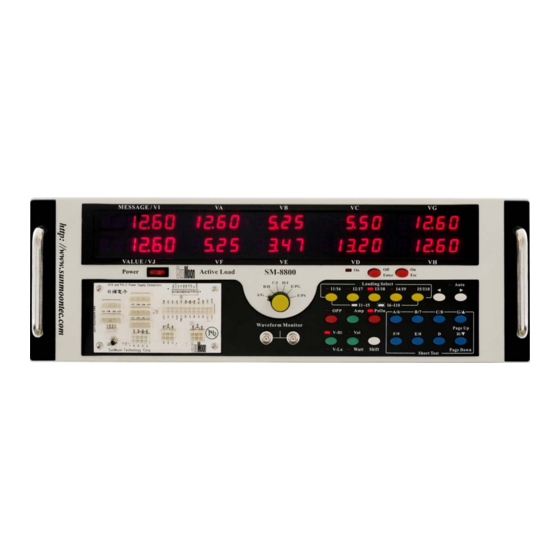
- Page 5 Front panel...
- Page 6 Rear Panel...
- Page 7 Please take out SM-8800 from the package. You can see a selection switch. (Please elevate SM-8800 so that you can see the selection switch of 110V /230V) If indoor voltage is AC 230V, please switch “Line Select” to 115V. Insert AC Power cord into the socket of SM-8800 rear panel “Line AC Input”.
- Page 8 “To S.P.S.” socket of SM-8800 rear panel and the socket of S.P.S. AC power input. Refer to figure 2-4. Insert the output of S.P.S. DC into the socket of SM-8800 front panel in the lower left side (such as ATX, ATX-20pin or 4P socket)
- Page 9 Figure2-5-1a External control switch connection Figure5-2-1b SM-8800 and R.C. external control switch connection 2-5-2 OUT1~OUT4 of I/O Port and external device connection Please arrange an external control circuit designed according to your need. (Refer to Figure2-5-2.) Connect the circuit to the terminals, OUT1, OUT2, OUT3, OUT4 and...
- Page 10 SM-8800.) Figure 2-5-2b is output circuit of Out1~4 and COM in I/O Port in SM-8800 rear panel. Figure2-5-2a SM-8800 and Out 1~4 external control connection Figure2-5-2b Output circuit of Out1~4 in “I/O Port” socket on rear panel and “COM” terminal...
- Page 11 2-5-3 PASS/FAIL output terminals of I/O Port and external control device connection Please make a control circuit that is designed according to your need for external device, the circuit in Figure2-5-3is for your reference. Connect the circuit and I/O port as shown in Figure2-5-3.
- Page 12 3 Operation panel description 3-1 Keypad of front panel description : 1. Power: AC on/off switch for SM-8800 2. I1/I6 ~ I5/I10:There are 10 selections of pre-set load current and power maximum and minimum. (Selections can be extended to 20 in automatic test mode.) When the switch is on, the mode I1~I5 is default.
- Page 13 3-2 Display window description (Refer to front panel) 1. MESSAGE / VI:To display voltages comparison, the result of time test, the information and result of automatic test, DC overall power, setting desceiption of the page, and the expansion of the 9th channel (VI) load. 2.
- Page 14 Figure3-2f (ATE 8-channel type) Fiugure3-2g (ATE 10-channel type) 7. After machine model and type are displayed, machine is in the standby mode. Refer to figure 3-2h, figure3-2i or figure3-2j. (Please refer to 5-2 parameters setting.) Standy mode means the moachine is: AC OFF S.P.S.
- Page 15 2. Line AC Input:This is input socket of machine power. When “Source Select” is selected at “INT”, AC power of S.P.S. is provided by this. 3. Line: To protect power fuse of machine. 4. Line Select : Select input voltage of AC power. The place of switch is under the base of Line Select→Under Base.
- Page 16 and judge voltage minimum and minimum setting, so the number in channel VA blinks. Press the button “▲” or “▼” to change channel VA minimum. Press the button“ ► ” to switch to channel VB so the number in channel VB blinks. Press “▲” or “▼” to change the maximum of channel VB.
- Page 17 4. Automatic test description There are 23 automatic test items for users to edit “test program”. 50 items can be edited in test program (including action and test items.)When the test starts, test programs are operated by sequence. When all tests are completed, it displays PASS or FAIL and the information of test results can be read. When S.P.S.
- Page 18 Test items specification (Item 2~7 are the part of time test. Refer to Figure4-1a) 0. END The test is completed. AC OFF and PsOff are controlled. Test result is displayed. 1. Loading Test To wait for Steady time according to the load set in Ix. (Refer to 5-3-2) Test value is input voltage of each channel.
- Page 19 Power Fail Time Test (P.F. Time Test) Boot the machine according to the load set in Ix and turn off input power of S.P.S. Zero the timer when Power Good signal of S.P.S. output changes from High to Low. Then, the machine starts timing at the same time and keeps testing +5 voltage of voltage terminal whether it equals to the voltage set by V or not.
- Page 20 automatic test in editing page OPPTION. Wait Boot the machine (according to the load set in Ix) and the program stops operating to wait for operators to adjust the voltage, read voltage ripple, check vibration test and test materials and terminals.
- Page 21 result will be FAIL. 圖 4-1b AC Meter Test ※ After AC power is on, AC power meter tests the following items: AC frequency AC peak voltage(PICK) AC power (RMS) AC voltage(RMS) AC current (RMS) Efficiency AC peak current(PICK) Power factor AC Meter Hold On ※Only the type with power meter has this function Turn on Hold On function of AC power meter to start Vp-Hold and Ip-Hold function to read the maximum Vp and Ip.
- Page 22 5 Condition and parameter setting 5-1 Shift+A:Switch manual test SM-8800 Auto model: Press the button Shift+A during standby mode in manual mode. If LED light Auto on the front panel (Refer to figure 5-1a) and a number shows on the upper left side of the monitor, (There are 10 channels of test programs.
- Page 23 Figure5-1d (8 channels are set.) Figure5-1e (10 channels are set.) 5-1-1 Press the button AC ON on the front panel in automatic test mode to start automatic test. When the test is completed, the monitor shows 3 kinds of results. 1.
- Page 24 3. FAIL: This represents test is abnormal. (Refer to figure 5-1-1f) and shows the test number of PASS/FAIL. Then, the machine sends a pulse signal from PASS/FAIL of I/O Port on the rear panel to control external devices. Figure5-1-1f Operate the buttons C/8 and D to browse test result for each test item. (Figure 5-1-1c, figure 5-1-1d or figure5-1-1e is showed according to channel total setting in Shift+B.) Operate the buttons ▲...
- Page 25 If there is Short Protect Test in automatic test program when test result of Short Protect Test items is browsed, VALUE will display the wrong code. Refer to 3 figures below. Meaning for each code:”0” represents test is normal. “1” represents T2 Time is judged wrong.
- Page 26 5-2-1 When 6 channels are set, channel VA~VF display 6 channels of voltage. Channel VG displays AC-V. Channel VH displays AC-I. Refer to the figure below. 5-2-2 When 8 channels are set, channel VA~VH displays 8 channels of voltage. (Refer to figure 5-2-2a) Press the button “►”...
- Page 27 5-3 Shift+C: Set auto-test parameters (It only works in standby mode) 5-3-1 CONF 1: Shift+C (Page 1) When S.P.S. is down in automatic test, judge voltage minimum of repeated booting. (Figure5-3-1a, figure5-3-1b or figure5-3-1c is showed according to total setting of channels in Shift+B.) Figure5-3-1a Figure5-3-1b v...
- Page 28 Table5-3-2 :To set up the auto test function parameter. Test channel VALUE Upper limit Lower limit form RETRY.T 32.00(Sec) 00.00 STEADY 8.00(Sec) 0.000 ATX/AT SHORT.M AC/DC SHORT.T 8.00(Sec) 0.30 READY.T 20.00(Sec) RETRY.T:Check output voltage of S.P.S. whether it is lower than RESET.V. or not (Refer to 5-3-1) or achieves the time setting to control action AC ON.
- Page 29 1.EFFI ㄩ 1.EFFI ㄇ 110.0 1.IP ㄩ 1.IP ㄇ 99.99 1.EQUA ㄩ 1.EQUA ㄇ 1.100 1.FREQ ㄩ:Maximum of AC frequency in first channel 1.V P ㄩ:Maximum of AC voltage pick in first channel 1.WATT ㄩ:Maximum of AC power (RMS) in first channel 1.I-RMS ㄩ:Maximum of AC current effeciency (RMS) in first channel 1.EFFI ㄩ:Maximum of effeciency in first channel 1.I P ㄩ:Maximum of AC current pick in first channel...
- Page 30 Channel VALUE Maximum Minimum Form 2.FREQ ㄩ 2.FREQ ㄇ 999.9 2.VP ㄩ 2.VP ㄇ 999.9 2.WATT ㄩ 2.WATT ㄇ 6500.0 2.VRMS ㄩ 2.VRMS ㄇ 999.9 2.IRMS ㄩ 2.IRMS ㄇ 99.99 2.EFFI ㄩ 2.EFFI ㄇ 110.0 2.IP ㄩ 2.IP ㄇ 99.99 2.EQUA ㄩ...
- Page 31 5-3-7 CONF 7 Shift+C (Page 7) Maximum parameters settings comparison of AC power meter for third channel Channel VALUE Maximum Minimum Form 3.FREQ ㄩ 3.FREQ ㄇ 999.9 3.VP ㄩ 3.VP ㄇ 999.9 3.WATT ㄩ 3.WATT ㄇ 6500.0 3.VRMS ㄩ 3.VRMS ㄇ 999.9 3.IRMS ㄩ...
- Page 32 3.I-RMS ㄇ:Minimum of AC current effeciency (RMS) in third channel 3.EFFI ㄇ:Minimum of effeciency in third channel 3.I P ㄇ:Minimum of AC current pick in third channel 3.EQUA ㄇ:Minimum of Power Factor in third channel 5-3-9 CONF 9 Shift+C (Page 9) Maximum parameters settings comparison of AC power meter for forrth channel Channel VALUE...
- Page 33 4.IP ㄇ 4.IP ㄩ 0.00 4.EQUA ㄇ 4.EQUA ㄩ 0.000 4.FREQ ㄇ:Minimum of AC frequency in fourth channel 4.V P ㄇ:Minimum of AC voltage pick in fourth channel 4.WATT ㄇ:Minimum of AC power (RMS) in fourth channel 4.I-RMS ㄇ:Minimum of AC current effeciency (RMS) in fourth channel 4.EFFI ㄇ:Minimum of effeciency in fourth channel 4.I P ㄇ:Minimum of AC current pick in fourth channel 4.EQUA ㄇ:Minimum of Power Factor in fourth channel...
- Page 34 2. When SHORT test item is selected, it indicates channels of short: 0=VI, 1=VA, 2=VB, 3=VC, 4=VG, 5=VH, 6=VD, 7=VE, 8=VF, 9=VJ 3. When LINE.IN test item is selected, it indicates the numbers of external AC is selected:1=IN-1、2=IN-2、3=IN-3 4. When LOOP test item is selected, it indicates the items of repeated test. It is counted as “one time”...
- Page 35 V2(V) 16.00 0.00 ON.TIME. (Power on): 0=no test, 1=PG, 2=ON.RING, =SETUP, 4=RISE time. OF.TIME. (Power off): 0=disable, 1= PF, 2=OF.RING, 3= HOLD. Vt:When 4 is selected in ON TIME, it indicates one of channels VA, VB, VE and VG is selected as input voltage.
- Page 36 RING ㄇ 0(Times) PG ㄇ 000.0(mS) 5-4-4 4. PF (Page4) Parameters setting time test items judgment that power off takes (The page is auto-test setting.) Parameters setting of PF, OF.RING and HOLD test items judgment. Channel VALUE Upper limit Lower limit Form PF ㄩ...
- Page 37 DOWN V 19.99 0.00 DOWN V 19.99 0.00 DOWN V 19.99 0.00 DOWN V 19.99 0.00 DOWN V 19.99 0.00 DOWN V: Judge voltage in down condition (Refer to table 5-4-5) Functions are below: 1. When S.P.S. down happens during teest, S.P.S. outputs all channels of voltages or one channel of voltages.
- Page 38 10 channels are set Channel VALUE Maximum Minimum Form STEP I 9.99 0.00 STEP I 9.99 0.00 STEP I 4.095 0.000 STEP I 9.99 0.00 STEP I 9.99 0.00 STEP I 4.095 0.000 STEP I 9.99 0.00 STEP I 4.095 0.000 STEP I 9.99...
- Page 39 END I 4.095 0.000 END I 60.00 0.00 END I 8.191 0.000 END I 20.47 0.00 END I 20.47 0.00 END I:When current achieves this setting, it stops increasing. 5-4-9 9. OPP.5 (Page9) (OPP related test parameters Page 5) Maximum and minimum parameters setting of OPP over power.
- Page 40 STEP I 4.095 0.000 STEP I 9.99 0.00 STEP I 4.095 0.000 STEP I 9.99 0.00 STEP I 9.99 0.00 STEP I:the rise current value of each step. refer to Table5-4-10 5-4-11 11. OCP2 (Page11) (OCP related test parameters Page2) Parameters setting of OCP current increment.
- Page 41 8 channels are set. 10 channels are set. Channel VALUE Maximum Minimum Form OCP ㄩ OCP ㄇ VA 40.95 OCP ㄩ OCP ㄇ VB 60.00 OCP ㄩ OCP ㄇ VC 4.095 OCP ㄩ OCP ㄇ VG 40.95 OCP ㄩ OCP ㄇ VH 40.95 OCP ㄩ...
- Page 42 Channel VALUE Maximum Minimum Form OCP ㄇ OCP ㄩ VA 0.00 OCP ㄇ OCP ㄩ VB 0.00 OCP ㄇ OCP ㄩ VC 0.000 OCP ㄇ OCP ㄩ VG 0.00 OCP ㄇ OCP ㄩ VH 0.00 OCP ㄇ OCP ㄩ VD 0.000 OCP ㄇ...
- Page 43 I1 ~ I20:Select to edit default current and voltage maximum/minimum from 1~20. SM-8800 can edit 20 default loads totally. Figure5-5-1 In figure 5-5-1, input default load numbers needed to be edited. The system quickly loads into default load parameters. This eliminates unnecessary actions of changing pages. Example: Input 05 to edit parameters in I5.
- Page 44 8 channels are set. 10 channels are set. Channel VALUE Maximum Minimum Form V HIGH 81.91 I1VL VA V HIGH 40.95 I1VL VB V HIGH 40.95 I1VL VC V HIGH 40.95 I1VL VG V HIGH 40.95 I1VL VH V HIGH 40.95 I1VL VD V HIGH...
- Page 45 10 channels are set. Channel VALUE Maximum Minimum Form V LOW I1VH VA 0.00 V LOW I1VH VB 0.00 V LOW I1VH VC 0.00 V LOW I1VH VG 0.00 V LOW I1VH VH 0.00 V LOW I1VH VD 0.00 V LOW I1VH VE 0.00 V LOW...
- Page 46 “Shift+PageDown” to turn to next page. 3. SET ORG1: Default settings are loaded in. Refer to the figure below. Press “Enter” to quit back to standby mode. Turn off SM-8800 and reboot it to load into default settings. Press “Shift+PageDown” to turn to next page.
- Page 47 If the machine fails in downloading information, the figure below will be displayed. If the machine succeeds in downloading information, the figure below will be displayed. When downloading is completed, it turns to standby mode. Turn off SM-8800 and reboot it. -46-...
- Page 48 Sun Moon Technology Corp. (Jinshan Road 5) Jinmei Range 91, Paishawei,Sunlane,Fenggang Town,Dongguang City,Guangdong Province,China TEL/FAX: +86769-87569046 or +86769-87772305 http:// www.sunmoontec.com E-Mail: sunmoon@sunmoontec.com -47-...
Need help?
Do you have a question about the SM-8800 and is the answer not in the manual?
Questions and answers