Bosch Rexroth IndraDrive CsDrive System with HCS01 Project Planning Manual
Hide thumbs
Also See for Rexroth IndraDrive CsDrive System with HCS01:
- Instruction manual (68 pages) ,
- Instruction manual (28 pages)

Related Manuals for Bosch Rexroth IndraDrive CsDrive System with HCS01


Summary of Contents for Bosch Rexroth IndraDrive CsDrive System with HCS01
- Page 1 Rexroth IndraDrive Cs Drive Systems with HCS01 Project Planning Manual Edition 05 R911322210...
- Page 2 © Bosch Rexroth AG 2016 Copyright This document, as well as the data, specifications and other information set forth in it, are the exclusive property of Bosch Rexroth AG. It may not be re‐ produced or given to third parties without its consent. Liability...
-
Page 3: Table Of Contents
DOK-INDRV*-HCS01******-PR05-EN-P Bosch Rexroth AG I/341 Rexroth IndraDrive CsDrive Systems with HCS01 Table of Contents Table of Contents Page System presentation...................... 9 Rexroth IndraDrive Cs range........................9 1.1.1 Overview – Rexroth IndraDrive Cs...................... 9 1.1.2 Target applications..........................10 1.1.3 Features............................11 Functional features......................... - Page 4 II/341 Bosch Rexroth AG DOK-INDRV*-HCS01******-PR05-EN-P Rexroth IndraDrive CsDrive Systems with HCS01 Table of Contents Page 3.3.4 Protection against electromagnetic and magnetic fields during operation and mounting....37 3.3.5 Protection against contact with hot parts................... 37 3.3.6 Protection during handling and mounting..................38 3.3.7...
- Page 5 DOK-INDRV*-HCS01******-PR05-EN-P Bosch Rexroth AG III/341 Rexroth IndraDrive CsDrive Systems with HCS01 Table of Contents Page 4.6.2 Project planning of control voltage....................69 Control voltage for drive systems....................69 Sizing the control voltage supply....................69 Determining the power requirements..................69 Requirements on the 24V power supply unit................73 Installing the 24V supply......................
- Page 6 IV/341 Bosch Rexroth AG DOK-INDRV*-HCS01******-PR05-EN-P Rexroth IndraDrive CsDrive Systems with HCS01 Table of Contents Page 5.2.1 Type Plates............................118 Arrangement..........................118 Design............................118 5.2.2 Scope of supply..........................119 Transporting the components......................120 Storing the components........................120 Mounting and installation................... 121 Mounting HCS01 Devices in the Control Cabinet................
- Page 7 DOK-INDRV*-HCS01******-PR05-EN-P Bosch Rexroth AG V/341 Rexroth IndraDrive CsDrive Systems with HCS01 Table of Contents Page X38, analog inputs/outputs (DA option)..................166 X41, Safe Motion safety technology..................... 167 X42, X43, Safe Motion safety technology (communication)............168 X49, optional safety technology L3 or L4..................169 X61, CANopen (CN Option)......................
- Page 8 VI/341 Bosch Rexroth AG DOK-INDRV*-HCS01******-PR05-EN-P Rexroth IndraDrive CsDrive Systems with HCS01 Table of Contents Page Incremental encoder emulation....................203 Connection..........................203 Electrical data..........................204 Absolute encoder emulation (SSI format)..................205 Connection..........................205 Electrical data..........................205 Pulse diagram..........................206 7.1.3 ET - Multi-Ethernet.......................... 207 Display elements..........................
- Page 9 DOK-INDRV*-HCS01******-PR05-EN-P Bosch Rexroth AG VII/341 Rexroth IndraDrive CsDrive Systems with HCS01 Table of Contents Page 7.3.3 DC bus............................. 240 7.3.4 Integrated braking resistor....................... 242 7.3.5 Inverter............................243 Cables, accessories, additional components............. 249 Overview............................. 249 8.1.1 Cables............................. 249 8.1.2 Accessories............................. 249 8.1.3...
- Page 10 VIII/341 Bosch Rexroth AG DOK-INDRV*-HCS01******-PR05-EN-P Rexroth IndraDrive CsDrive Systems with HCS01 Table of Contents Page Type code............................. 297 Type plate............................. 298 HNL01.1E - mains chokes, feeding ..................... 299 Technical data........................... 299 8.3.4 External braking resistors HLR......................301 Types............................301 Data.............................. 301 HLR01.2N-01K0-N28R0, ...-N68R0 dimensions................
-
Page 11: System Presentation
DOK-INDRV*-HCS01******-PR05-EN-P Bosch Rexroth AG 9/341 Rexroth IndraDrive CsDrive Systems with HCS01 System presentation System presentation Rexroth IndraDrive Cs range 1.1.1 Overview – Rexroth IndraDrive Cs Rexroth IndraDrive Cs HCS01 converter MSM, MS2N, MSK, MCL motors; third-party motors Tab. 1-1: Components of the Rexroth IndraDrive Cs range... -
Page 12: Target Applications
10/341 Bosch Rexroth AG DOK-INDRV*-HCS01******-PR05-EN-P Rexroth IndraDrive CsDrive Systems with HCS01 System presentation 1.1.2 Target applications General automation, handling, assembly Automated assembly and handling systems, palletizing systems, pick-and-place systems, logistics … Machine tools Compact machines (e.g., for wood machining), secondary and servo drives …... -
Page 13: Features
DOK-INDRV*-HCS01******-PR05-EN-P Bosch Rexroth AG 11/341 Rexroth IndraDrive CsDrive Systems with HCS01 System presentation 1.1.3 Features Functional features ● Compact type of construction ● Degree of protection IP20 ● Control panel with programming module function ● Scalable signal processing and firmware ●... - Page 14 12/341 Bosch Rexroth AG DOK-INDRV*-HCS01******-PR05-EN-P Rexroth IndraDrive CsDrive Systems with HCS01 System presentation HCS01 - ECONOMY vs. BASIC vs. ADVANCED HCS01.1E-W00**-A-0*-… …E-S3 …B-ET …A-CC, …A-ET Functional equipment (ECONOMY) (BASIC) (ADVANCED) Communication sercos III / EtherCAT Multi-Ethernet CC: sercos III master (cross communication) (incl.
-
Page 15: Performance Features
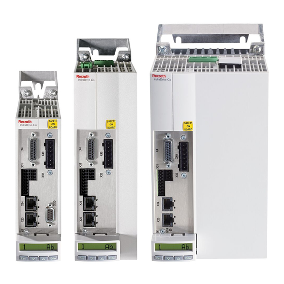
DOK-INDRV*-HCS01******-PR05-EN-P Bosch Rexroth AG 13/341 Rexroth IndraDrive CsDrive Systems with HCS01 System presentation Performance features Size 3 Size 1 Size 2 (Width: 130 mm; (Width: 50 mm; Height: 215 mm) (Width: 70 mm; Height: 268 mm) Height: 268 mm) HCS01.1E-W00… →... -
Page 16: Combination Of Hcs01 And Msm/Msk
14/341 Bosch Rexroth AG DOK-INDRV*-HCS01******-PR05-EN-P Rexroth IndraDrive CsDrive Systems with HCS01 System presentation Combination of HCS01 and MSM/MSK HCS01 3 AC 110 … 230 V 3 AC 200 … 500 V W0003 W0006 W0009 W0013 W0018 W0005 W0008 W0018 W0028 W0054 ■... -
Page 17: Supported Encoder Systems
DOK-INDRV*-HCS01******-PR05-EN-P Bosch Rexroth AG 15/341 Rexroth IndraDrive CsDrive Systems with HCS01 System presentation Supported encoder systems Supported encoder systems Encoder systems with a supply voltage of 5 and 12 V: ● MSM motor encoder ● MS2N motor encoder ● MSK motor encoder ●... -
Page 18: System Configuration
16/341 Bosch Rexroth AG DOK-INDRV*-HCS01******-PR05-EN-P Rexroth IndraDrive CsDrive Systems with HCS01 System presentation System configuration 1.2.1 System structure Optional Control voltage supply Communication Autotransformer Fuses HCS01 Converter DC bus capacitor unit (for devices with DC bus connection) External braking resistor... -
Page 19: System Components
DOK-INDRV*-HCS01******-PR05-EN-P Bosch Rexroth AG 17/341 Rexroth IndraDrive CsDrive Systems with HCS01 System presentation 1.2.2 System components HCS01 drive controllers Type code Short type designation 1 2 3 4 5 6 7 8 9 0 1 2 3 4 5 6 7 8 9... -
Page 20: Tions
18/341 Bosch Rexroth AG DOK-INDRV*-HCS01******-PR05-EN-P Rexroth IndraDrive CsDrive Systems with HCS01 System presentation Short type designation 1 2 3 4 5 6 7 8 9 0 1 2 3 4 5 6 7 8 9 0 1 2 3 4 5 6 7 8 9... -
Page 21: Tions
DOK-INDRV*-HCS01******-PR05-EN-P Bosch Rexroth AG 19/341 Rexroth IndraDrive CsDrive Systems with HCS01 System presentation Possible combinations of options: Control section Communication Interface 2 Interface 3 design ✓ – ✓ ✓ – ✓ ✓ ✓ ✓ ✓ ✓ ✓ ✓ ✓ –... -
Page 22: Hap01 Control Panel
20/341 Bosch Rexroth AG DOK-INDRV*-HCS01******-PR05-EN-P Rexroth IndraDrive CsDrive Systems with HCS01 System presentation HAP01 control panel View Fig. 1-2: HAP01 control panel Type code Short type designation 1 2 3 4 5 6 7 8 9 0 1 2 3 4 5 6 7 8 9... -
Page 23: Firmware
DOK-INDRV*-HCS01******-PR05-EN-P Bosch Rexroth AG 21/341 Rexroth IndraDrive CsDrive Systems with HCS01 System presentation HAP01 ↔ HCS01 assignment Control panel Drive controller HAP01.1A HCS01.1E-W****-*-**-A-CC (ADVANCED) HCS01.1E-W****-*-**-A-ET (ADVANCED) HCS01.1E-W****-*-**-B-ET (BASIC) HCS01.1E-W****-*-**-E-S3 (ECONOMY) HAP01.1N HCS01.1E-W****-*-**-B-ET (BASIC) HCS01.1E-W****-*-**-E-S3 (ECONOMY) Requires firmware MPx-20 or higher Tab. -
Page 24: About This Documentation
22/341 Bosch Rexroth AG DOK-INDRV*-HCS01******-PR05-EN-P Rexroth IndraDrive CsDrive Systems with HCS01 System presentation 1.2.3 About this documentation Purpose Personal injury and property damage caused WARNING by improper project planning for applications, machines and installations! Observe the contents of the documentation relevant to your drive system (see chapter "Documentations"... -
Page 25: Tions
DOK-INDRV*-HCS01******-PR05-EN-P Bosch Rexroth AG 23/341 Rexroth IndraDrive CsDrive Systems with HCS01 System presentation Edition Notes Changes in comparison to previous edition: New contents ● Safety technology Safe Motion (optional module S4) ● Analog/digital I/O extension (optional module DA) ● HAS05.1-015-NNN-NN (snap-on ferrite) accessory Revised contents ●... -
Page 26: Tions
24/341 Bosch Rexroth AG DOK-INDRV*-HCS01******-PR05-EN-P Rexroth IndraDrive CsDrive Systems with HCS01 System presentation Edition Notes Changes in comparison to previous edition: New contents ● HCS01.1E-W0054-_-03 ● HCS01.1E-W0018-_-02 ● Safety technology (L3, L4) ● Encoder emulation (EM) ● CANopen (CN) communication ●... -
Page 27: Documentations
DOK-INDRV*-HCS01******-PR05-EN-P Bosch Rexroth AG 25/341 Rexroth IndraDrive CsDrive Systems with HCS01 System presentation Documentations Drive systems, system components Title Type of documentation Material number Document typecode Rexroth IndraDrive … R911… DOK-INDRV*-… Cs drive systems Project Planning Manual HCS01******-PRxx-EN-P 322210 In the document typecodes, "xx" is a placeholder for the current edition of the documentation (e.g.: PR01 is the first edition of a... -
Page 28: Firmware
26/341 Bosch Rexroth AG DOK-INDRV*-HCS01******-PR05-EN-P Rexroth IndraDrive CsDrive Systems with HCS01 System presentation Firmware Title Type of documentation Material number Document typecode Rexroth IndraDrive ... R911… DOK-INDRV*-… MPx-20 Application Manual MP*-20VRS**-APxx-EN-P 345608 Functions MPx-20 Release Notes MP*-20VRS**-RNxx-EN-P 345606 Version Notes... -
Page 29: Your Feedback
DOK-INDRV*-HCS01******-PR05-EN-P Bosch Rexroth AG 27/341 Rexroth IndraDrive CsDrive Systems with HCS01 System presentation Your feedback Your experience is important for our improvement processes of products and documentations. Inform us about mistakes you discovered in this documentation and changes you suggest; we would be grateful for your feedback. - Page 30 28/341 Bosch Rexroth AG DOK-INDRV*-HCS01******-PR05-EN-P Rexroth IndraDrive CsDrive Systems with HCS01...
-
Page 31: Important Directions For Use
DOK-INDRV*-HCS01******-PR05-EN-P Bosch Rexroth AG 29/341 Rexroth IndraDrive CsDrive Systems with HCS01 Important directions for use Important directions for use Appropriate use 2.1.1 Introduction Rexroth products represent state-of-the-art developments and manufacturing. They are tested prior to delivery to ensure operating safety and reliability. -
Page 32: Inappropriate Use
30/341 Bosch Rexroth AG DOK-INDRV*-HCS01******-PR05-EN-P Rexroth IndraDrive CsDrive Systems with HCS01 Important directions for use To ensure application-specific use of Drive controllers, device types of differ‐ ent drive power and different interfaces are available. Typical applications include, for example: ●... -
Page 33: Safety Instructions For Electric Drives And Controls
DOK-INDRV*-HCS01******-PR05-EN-P Bosch Rexroth AG 31/341 Rexroth IndraDrive CsDrive Systems with HCS01 Safety instructions for electric drives and controls Safety instructions for electric drives and controls Definitions of terms Application documentation Application documentation comprises the entire documentation used to in‐ form the user of the product about the use and safety-relevant features for configuring, integrating, installing, mounting, commissioning, operating, main‐... -
Page 34: General Information
32/341 Bosch Rexroth AG DOK-INDRV*-HCS01******-PR05-EN-P Rexroth IndraDrive CsDrive Systems with HCS01 Safety instructions for electric drives and controls requires. To comply with these qualifications, it is necessary, among other things, ● to be trained, instructed or authorized to switch electric circuits and devi‐... -
Page 35: Hazards By Improper Use
DOK-INDRV*-HCS01******-PR05-EN-P Bosch Rexroth AG 33/341 Rexroth IndraDrive CsDrive Systems with HCS01 Safety instructions for electric drives and controls ● Applications for functional safety are only allowed if clearly and explicitly specified in the application documentation "Integrated Safety Technolo‐ gy". If this is not the case, they are excluded. Functional safety is a safe‐... -
Page 36: Instructions With Regard To Specific Dangers
34/341 Bosch Rexroth AG DOK-INDRV*-HCS01******-PR05-EN-P Rexroth IndraDrive CsDrive Systems with HCS01 Safety instructions for electric drives and controls ● Health hazard for persons with heart pacemakers, metal implants and hearing aids in proximity to electric drive systems! ● Risk of burns by hot housing surfaces! ●... -
Page 37: Protective Extra-Low Voltage As Protection Against Electric Shock
DOK-INDRV*-HCS01******-PR05-EN-P Bosch Rexroth AG 35/341 Rexroth IndraDrive CsDrive Systems with HCS01 Safety instructions for electric drives and controls ● Secure built-in devices from penetrating foreign objects and water, as well as from direct contact, by providing an external housing, for exam‐... -
Page 38: Protection Against Dangerous Movements
36/341 Bosch Rexroth AG DOK-INDRV*-HCS01******-PR05-EN-P Rexroth IndraDrive CsDrive Systems with HCS01 Safety instructions for electric drives and controls Danger to life, risk of injury by electric shock! High electrical voltage by incor‐ rect connection! If extra-low voltage circuits of devices containing voltages and circuits of more than 50 volts (e.g., the mains connection) are connected to Rexroth... -
Page 39: Protection Against Electromagnetic And Magnetic Fields During Operation And Mounting
DOK-INDRV*-HCS01******-PR05-EN-P Bosch Rexroth AG 37/341 Rexroth IndraDrive CsDrive Systems with HCS01 Safety instructions for electric drives and controls ment works. Do not operate the machine if the emergency stopping switch is not working. ● Prevent unintended start-up. Isolate the drive power connection by means of OFF switches/OFF buttons or use a safe starting lockout. -
Page 40: Protection During Handling And Mounting
38/341 Bosch Rexroth AG DOK-INDRV*-HCS01******-PR05-EN-P Rexroth IndraDrive CsDrive Systems with HCS01 Safety instructions for electric drives and controls ● Do not touch hot surfaces of, for example, braking resistors, heat sinks, supply units and drive controllers, motors, windings and laminated cores! ●... -
Page 41: Protection Against Pressurized Systems
DOK-INDRV*-HCS01******-PR05-EN-P Bosch Rexroth AG 39/341 Rexroth IndraDrive CsDrive Systems with HCS01 Safety instructions for electric drives and controls Environmental protection and disposal! The batteries contained in the product are considered dangerous goods during land, air, and sea transport (risk of explosion) in the sense of the legal regula‐... -
Page 42: Explanation Of Signal Words And The Safety Alert Symbol
40/341 Bosch Rexroth AG DOK-INDRV*-HCS01******-PR05-EN-P Rexroth IndraDrive CsDrive Systems with HCS01 Safety instructions for electric drives and controls Explanation of signal words and the Safety alert symbol The Safety Instructions in the available application documentation contain specific signal words (DANGER, WARNING, CAUTION or NOTICE) and,... -
Page 43: Combining The Individual Components
DOK-INDRV*-HCS01******-PR05-EN-P Bosch Rexroth AG 41/341 Rexroth IndraDrive CsDrive Systems with HCS01 Combining the individual components Combining the individual components Documentations chapter "Documentations" on page 25 Brief description of individual components 4.2.1 HCS01 - brief description and design The compact converters HCS01 are part of the Rexroth IndraDrive Cs prod‐... - Page 44 42/341 Bosch Rexroth AG DOK-INDRV*-HCS01******-PR05-EN-P Rexroth IndraDrive CsDrive Systems with HCS01 Combining the individual components Mains Type and Mains Voltage IT mains TN-S mains Mains grounded via outer conductor TN-C mains TT mains Mains voltage ≤ 3 AC 230V Mains voltage 3 AC 230 … 500 V To be noticed with 1-phase mains volt‐...
-
Page 45: Functional Equipment
DOK-INDRV*-HCS01******-PR05-EN-P Bosch Rexroth AG 43/341 Rexroth IndraDrive CsDrive Systems with HCS01 Combining the individual components 4.3.2 Functional equipment HCS01 - ECONOMY vs. BASIC vs. ADVANCED HCS01.1E-W00**-A-0*-… …E-S3 …B-ET …A-CC, …A-ET Functional equipment (ECONOMY) (BASIC) (ADVANCED) Communication sercos III / EtherCAT... -
Page 46: Firmware
44/341 Bosch Rexroth AG DOK-INDRV*-HCS01******-PR05-EN-P Rexroth IndraDrive CsDrive Systems with HCS01 Combining the individual components 4.3.3 Firmware Firmware and device types Device type Firmware HCS01.1E-W00**-A-0*-E-S3 (ECONOMY) FWA-INDRV*-MPE-16VRS-D5-x-NNN-NN FWA-INDRV*-MPE-17VRS-D5-x-NNN-NN FWA-INDRV*-MPE-18VRS-D5-x-NNN-NN FWA-INDRV*-MPE-20VRS-D5-x-NNN-NN HCS01.1E-W00**-A-0*-B-ET (BASIC) FWA-INDRV*-MPB-16VRS-D5-x-xxx-xx FWA-INDRV*-MPB-17VRS-D5-x-xxx-xx FWA-INDRV*-MPB-18VRS-D5-x-xxx-xx FWA-INDRV*-MPB-20VRS-D5-x-xxx-xx HCS01.1E-W00**-A-0*-A-CC (ADVANCED) FWA-INDRV*-MPC-17VRS-D5-x-xxx-xx FWA-INDRV*-MPC-18VRS-D5-x-xxx-xx FWA-INDRV*-MPC-20VRS-D5-x-xxx-xx HCS01.1E-W00**-A-0*-A-ET (ADVANCED) -
Page 47: Tions
DOK-INDRV*-HCS01******-PR05-EN-P Bosch Rexroth AG 45/341 Rexroth IndraDrive CsDrive Systems with HCS01 Combining the individual components ● MPB → Firmware with BASIC performance and BASIC functionality ● MPC → Firmware with ADVANCED performance and ADVANCED func‐ tionality Characteristic (open-loop/closed-loop) ● 0 → Open-loop ●... -
Page 48: Firmware Variants
46/341 Bosch Rexroth AG DOK-INDRV*-HCS01******-PR05-EN-P Rexroth IndraDrive CsDrive Systems with HCS01 Combining the individual components Firmware variants MPx-xxVRS Firmware variant → Firmware characteristic → Base package Basic functions ■ ■ ■ ■ ■ ■ Base package "open-loop" ■ ■ ■... -
Page 49: Motors
DOK-INDRV*-HCS01******-PR05-EN-P Bosch Rexroth AG 47/341 Rexroth IndraDrive CsDrive Systems with HCS01 Combining the individual components 4.3.4 Motors IndraDyn The table below contains an overview of the combinations of MSM motors with HCS01 converters. HCS01 Size 1 Size 2 Size 3 3 AC 110 …... -
Page 50: Third-Party Motors
48/341 Bosch Rexroth AG DOK-INDRV*-HCS01******-PR05-EN-P Rexroth IndraDrive CsDrive Systems with HCS01 Combining the individual components Third-Party Motors General Information on Third-Party Motors Why Use Third-Party Motors at Rexroth IndraDrive Cs Controllers? Today, machine axes are mainly moved with electric drives. Motors of stand‐... -
Page 51: Requirements On Third-Party Motors
DOK-INDRV*-HCS01******-PR05-EN-P Bosch Rexroth AG 49/341 Rexroth IndraDrive CsDrive Systems with HCS01 Combining the individual components Observe the restrictions in conjunction with the commutation off‐ set determination when using synchronous motors! See firmware documentation, chapter "Drive Control", "Commutation Setting". Possibly available reluctance property cannot be used for syn‐... - Page 52 50/341 Bosch Rexroth AG DOK-INDRV*-HCS01******-PR05-EN-P Rexroth IndraDrive CsDrive Systems with HCS01 Combining the individual components ● With mains voltage up to 3 AC 230 V: Allowed periodic peak voltage (crest value) of third-party motor between phase-phase and phase-housing: < 850 V (To operate motors which do not require any voltage-reducing compo‐...
-
Page 53: Tions
DOK-INDRV*-HCS01******-PR05-EN-P Bosch Rexroth AG 51/341 Rexroth IndraDrive CsDrive Systems with HCS01 Combining the individual components When the inductance is measured, different inductance values can be determined at different rotor positions within one pole pair distance of the motor. The average value is relevant for the check of the minimum value. -
Page 54: Requirements On The Encoder Of The Third-Party Motor
52/341 Bosch Rexroth AG DOK-INDRV*-HCS01******-PR05-EN-P Rexroth IndraDrive CsDrive Systems with HCS01 Combining the individual components Requirements on the Encoder of the Third-Party Motor Motor Encoder of Asynchronous Third-Party Motor Asynchronous motors can also be controlled by Rexroth IndraDrive Cs con‐... -
Page 55: Cables
DOK-INDRV*-HCS01******-PR05-EN-P Bosch Rexroth AG 53/341 Rexroth IndraDrive CsDrive Systems with HCS01 Combining the individual components The continuous current of the drive controller should be greater than the continuous current of the motor. The continuous power of the drive controller must be greater than... -
Page 56: Encoder Cables
54/341 Bosch Rexroth AG DOK-INDRV*-HCS01******-PR05-EN-P Rexroth IndraDrive CsDrive Systems with HCS01 Combining the individual components Encoder cables MSM motors HCS01 Size 1 Size 2 Size 3 3 AC 110 … 230 V 3 AC 200 … 500 V Motor W0003... -
Page 57: Tions
DOK-INDRV*-HCS01******-PR05-EN-P Bosch Rexroth AG 55/341 Rexroth IndraDrive CsDrive Systems with HCS01 Combining the individual components that ambient and operating conditions have actually been observed. The power dissipation is indicated in the technical data of the individual compo‐ nents as an important input value for calculating the heat levels. -
Page 58: Control Cabinet Design And Cooling
56/341 Bosch Rexroth AG DOK-INDRV*-HCS01******-PR05-EN-P Rexroth IndraDrive CsDrive Systems with HCS01 Combining the individual components Description Symbol Unit Value Derating vs. installation altitude: At an installation altitude h > h , the perform‐ ance data reduced by factor f is available. - Page 59 DOK-INDRV*-HCS01******-PR05-EN-P Bosch Rexroth AG 57/341 Rexroth IndraDrive CsDrive Systems with HCS01 Combining the individual components Possibilities of heat dissipation Closed control cabinet with Closed control cabinet with Control cabinet with fan Closed control cabinet with air circulation heat exchanger air conditioning unit...
-
Page 60: Ul Ratings
58/341 Bosch Rexroth AG DOK-INDRV*-HCS01******-PR05-EN-P Rexroth IndraDrive CsDrive Systems with HCS01 Combining the individual components Control cabinet ventilation (sche‐ matic diagram) Control cabinet Air outlet opening Heat discharge Device in control cabinet Control cabinet fan Filter at air intake opening Fig. -
Page 61: Compatibility With Foreign Matters
DOK-INDRV*-HCS01******-PR05-EN-P Bosch Rexroth AG 59/341 Rexroth IndraDrive CsDrive Systems with HCS01 Combining the individual components HCS01.1E HCS01.1E HCS01.1E HCS01.1E HCS01.1E Description Symbol Unit -W0003- -W0006- -W0009- -W0013- -W0018- _-02 _-02 _-02 _-02 _-02 Output voltage 3 x AC 0...230 Output current Last modification: 2012-01-23 Mains input L1, L2, L3 (for HMV and HCS only);... - Page 62 60/341 Bosch Rexroth AG DOK-INDRV*-HCS01******-PR05-EN-P Rexroth IndraDrive CsDrive Systems with HCS01 Combining the individual components HCS01.1E-W0003/5/6/8/9/13 Standard mounting: Minimum mounting clearance Boring dimensions Mounting surface Fig. 4-4: Dimensional Drawing HCS01.1E-W0003/5/6/8/9/13 (Standard Mounting) Left-hand or right-hand mounting: Minimum mounting clearance Boring dimensions Mounting surface Fig.
- Page 63 DOK-INDRV*-HCS01******-PR05-EN-P Bosch Rexroth AG 61/341 Rexroth IndraDrive CsDrive Systems with HCS01 Combining the individual components HCS01.1E-W0018/28 Standard mounting: Minimum mounting clearance Boring dimensions Mounting surface Fig. 4-6: Dimensional Drawing HCS01.1E-W0018/28 (Standard Mounting) Left-hand or right-hand mounting: Minimum mounting clearance Boring dimensions Mounting surface Fig.
- Page 64 62/341 Bosch Rexroth AG DOK-INDRV*-HCS01******-PR05-EN-P Rexroth IndraDrive CsDrive Systems with HCS01 Combining the individual components HCS01.1E-W0054 Standard mounting: Minimum mounting clearance Boring dimensions Mounting surface Fig. 4-8: Dimensional Drawing HCS01.1E-W0054 (Standard Mounting) Left-hand or right-hand mounting: Minimum mounting clearance Boring dimensions Mounting surface Fig.
-
Page 65: Dimensions, Mass, Insulation, Sound Pressure Level
DOK-INDRV*-HCS01******-PR05-EN-P Bosch Rexroth AG 63/341 Rexroth IndraDrive CsDrive Systems with HCS01 Combining the individual components Dimensions, mass, insulation, sound pressure level Data for mass, dimensions, sound pressure level, insulation HCS01.1E HCS01.1E HCS01.1E HCS01.1E HCS01.1E Description Symbol Unit -W0003- -W0006- -W0009-... -
Page 66: Temperatures, Cooling, Power Dissipation, Distances
64/341 Bosch Rexroth AG DOK-INDRV*-HCS01******-PR05-EN-P Rexroth IndraDrive CsDrive Systems with HCS01 Combining the individual components Temperatures, cooling, power dissipation, distances Cooling and power dissipation data HCS01.1E HCS01.1E HCS01.1E HCS01.1E HCS01.1E Description Symbol Unit -W0003- -W0006- -W0009- -W0013- -W0018- _-02 _-02... - Page 67 DOK-INDRV*-HCS01******-PR05-EN-P Bosch Rexroth AG 65/341 Rexroth IndraDrive CsDrive Systems with HCS01 Combining the individual components Cooling and power dissipation data HCS01.1E HCS01.1E HCS01.1E HCS01.1E HCS01.1E Description Symbol Unit -W0005- -W0008- -W0018- -W0028- -W0054- _-03 _-03 _-03 _-03 _-03 Ambient temperature range for °C...
- Page 68 66/341 Bosch Rexroth AG DOK-INDRV*-HCS01******-PR05-EN-P Rexroth IndraDrive CsDrive Systems with HCS01 Combining the individual components Property damage due to temperatures higher NOTICE than 105 ℃! Observe the indicated minimum distances! Above the devices there may only be such materials which ●...
-
Page 69: Mounting Positions Of Components
DOK-INDRV*-HCS01******-PR05-EN-P Bosch Rexroth AG 67/341 Rexroth IndraDrive CsDrive Systems with HCS01 Combining the individual components Mounting Positions of Components Risk of damage to the components! NOTICE Only operate the components in their allowed mounting positions. Only the mounting position G1 is allowed for HCS01 components. -
Page 70: Electrical Project Planning
68/341 Bosch Rexroth AG DOK-INDRV*-HCS01******-PR05-EN-P Rexroth IndraDrive CsDrive Systems with HCS01 Combining the individual components Electrical project planning 4.6.1 Overall connection diagram Optional ECONOMY = sercos III; BASIC = Multi-Ethernet; ADVANCED = sercos III master Only exists at ADVANCED devices and devices with Engineer‐... -
Page 71: Project Planning Of Control Voltage
DOK-INDRV*-HCS01******-PR05-EN-P Bosch Rexroth AG 69/341 Rexroth IndraDrive CsDrive Systems with HCS01 Combining the individual components 4.6.2 Project planning of control voltage Control voltage for drive systems Some components of a drive system have to be supplied with control voltage. When doing the project planning for control voltage supply, include the drive system component requirements: ●... - Page 72 70/341 Bosch Rexroth AG DOK-INDRV*-HCS01******-PR05-EN-P Rexroth IndraDrive CsDrive Systems with HCS01 Combining the individual components Type code example: Basic device (maximum current [W0028 = 28 A], series [03], on-board connection point [EC]) Control section design (E = Economy; S3 = sercos III) Optional connection points (PB = ProfiBus;...
- Page 73 DOK-INDRV*-HCS01******-PR05-EN-P Bosch Rexroth AG 71/341 Rexroth IndraDrive CsDrive Systems with HCS01 Combining the individual components Table 2: Power requirement of the optional connection point Optional connec‐ Power re‐ Explanation tion point quirement (Identifier in type code) Encoder systems ● MSM motor encoder ●...
- Page 74 72/341 Bosch Rexroth AG DOK-INDRV*-HCS01******-PR05-EN-P Rexroth IndraDrive CsDrive Systems with HCS01 Combining the individual components Table 3: Power requirements of the external loads External load Power requirement 5 V encoder system P = I × 5 V × 1.75 1), 5)
-
Page 75: Requirements On The 24V Power Supply Unit
DOK-INDRV*-HCS01******-PR05-EN-P Bosch Rexroth AG 73/341 Rexroth IndraDrive CsDrive Systems with HCS01 Combining the individual components Requirements on the 24V power supply unit PELV for 24V power supply unit For the 24V supply of the devices of the Rexroth IndraDrive Cs range, use a power supply unit or a control-power transformer with protection by PELV according to IEC 60204-1 (section 6.4). - Page 76 74/341 Bosch Rexroth AG DOK-INDRV*-HCS01******-PR05-EN-P Rexroth IndraDrive CsDrive Systems with HCS01 Combining the individual components ● Route lines of sufficient size to reduce load-dependent voltage drops. ● For looping through the control voltage, observe the maximum current carrying capacity of the connection points. The maximum current carry‐...
-
Page 77: Mains Connection
DOK-INDRV*-HCS01******-PR05-EN-P Bosch Rexroth AG 75/341 Rexroth IndraDrive CsDrive Systems with HCS01 Combining the individual components Looping through the control volt‐ Property damage in case of error from line NOTICE cross section being too small! Observe the current carrying capacity of the connection points for control voltage supply at the components used. -
Page 78: Cause Of Leakage Currents
76/341 Bosch Rexroth AG DOK-INDRV*-HCS01******-PR05-EN-P Rexroth IndraDrive CsDrive Systems with HCS01 Combining the individual components ● for switch-on processes, due to high asymmetric inrush currents and ● during operation of the installation, due to leakage currents produced in normal operation. -
Page 79: Using Residual-Current-Operated Circuit Breakers At Hcs Drive Controllers
DOK-INDRV*-HCS01******-PR05-EN-P Bosch Rexroth AG 77/341 Rexroth IndraDrive CsDrive Systems with HCS01 Combining the individual components the residual-current-operated circuit breaker is not triggered. This blocks the triggering of a residual-current-operated circuit breaker sensitive to power pulse current in the case of ground contact, i.e. in the case of error. -
Page 80: Mains Types
78/341 Bosch Rexroth AG DOK-INDRV*-HCS01******-PR05-EN-P Rexroth IndraDrive CsDrive Systems with HCS01 Combining the individual components ● Each residual-current-operated circuit breaker only supplies one drive controller ● Only Rexroth components and accessories including cables and filters are used Mains types TN-S mains type The TN-S mains type is the usual mains type in Europe. -
Page 81: Tn-C Mains Type
DOK-INDRV*-HCS01******-PR05-EN-P Bosch Rexroth AG 79/341 Rexroth IndraDrive CsDrive Systems with HCS01 Combining the individual components TN-C mains type Direct grounding of a point (station ground) Exposed conductive parts directly connected to station ground Neutral conductor and equipment grounding conductor func‐... -
Page 82: Tt System
80/341 Bosch Rexroth AG DOK-INDRV*-HCS01******-PR05-EN-P Rexroth IndraDrive CsDrive Systems with HCS01 Combining the individual components Notes on project planning Risk to damage to devices from voltage arc‐ NOTICE ing. For applications with static charging (e.g., printing, packaging) and operation on IT mains type, use an isolating transformer with V ≤... -
Page 83: Mains With Grounded Outer Conductor (Corner-Grounded Delta Mains)
DOK-INDRV*-HCS01******-PR05-EN-P Bosch Rexroth AG 81/341 Rexroth IndraDrive CsDrive Systems with HCS01 Combining the individual components Mains with grounded outer conductor (Corner-grounded delta mains) Isolation of all active parts from ground, connection of one phase - generally phase V - to ground or via an impedance R... -
Page 84: Tions
82/341 Bosch Rexroth AG DOK-INDRV*-HCS01******-PR05-EN-P Rexroth IndraDrive CsDrive Systems with HCS01 Combining the individual components Individual supply Individual supply Group supply Central supply With 1-phase mains supply, you can connect the mains supply line to connector X3 at L1, L2 or L3 Tab. - Page 85 DOK-INDRV*-HCS01******-PR05-EN-P Bosch Rexroth AG 83/341 Rexroth IndraDrive CsDrive Systems with HCS01 Combining the individual components One powerful component supplies other components via the common DC bus connection. Components marked with gray background color: Optional, de‐ pending on the application Component HCS01 (more powerful than component B); con‐...
-
Page 86: Tions
84/341 Bosch Rexroth AG DOK-INDRV*-HCS01******-PR05-EN-P Rexroth IndraDrive CsDrive Systems with HCS01 Combining the individual components Components marked with gray background color: Option‐ al, depending on the application; the choke is used to re‐ duce current harmonics Component HCS01 (all components A identical); connec‐... -
Page 87: Mains Connected Load And Mains Current
DOK-INDRV*-HCS01******-PR05-EN-P Bosch Rexroth AG 85/341 Rexroth IndraDrive CsDrive Systems with HCS01 Combining the individual components Components marked with gray background color: Optional, de‐ pending on the application; the choke is used to reduce current harmonics Component HCS01 (more powerful than component B); con‐... -
Page 88: Tions
86/341 Bosch Rexroth AG DOK-INDRV*-HCS01******-PR05-EN-P Rexroth IndraDrive CsDrive Systems with HCS01 Combining the individual components Mechanical nominal power for main drives (shaft output) [kW] Nominal motor torque [Nm] Nominal motor speed [min Determine DC bus power from motor power and efficiency... -
Page 89: Dimensioning The Line Cross Sections And Fuses
DOK-INDRV*-HCS01******-PR05-EN-P Bosch Rexroth AG 87/341 Rexroth IndraDrive CsDrive Systems with HCS01 Combining the individual components Dimensioning the line cross sections and fuses Dimensioning the line cross sections and fuses in the supply feeder and branches to the drive system: Determine current in supply feeder of drive system... -
Page 90: Tions
88/341 Bosch Rexroth AG DOK-INDRV*-HCS01******-PR05-EN-P Rexroth IndraDrive CsDrive Systems with HCS01 Combining the individual components Country of use: international except for USA/Canada Fuse I Current carrying ca‐ Cross section A [mm pacity (× 0.87) I Installation type B1 Z(40) 1 ×... -
Page 91: Tions
DOK-INDRV*-HCS01******-PR05-EN-P Bosch Rexroth AG 89/341 Rexroth IndraDrive CsDrive Systems with HCS01 Combining the individual components Country of use: international except for USA/Canada Fuse I Current carrying ca‐ Cross section A [mm pacity (× 0.87) I Installation type B2 Z(40) 1 ×... -
Page 92: Tions
90/341 Bosch Rexroth AG DOK-INDRV*-HCS01******-PR05-EN-P Rexroth IndraDrive CsDrive Systems with HCS01 Combining the individual components Country of use: international except for USA/Canada Fuse I Current carrying ca‐ Cross section A [mm pacity (× 0.87) I Installation type E Z(40) 1 ×... - Page 93 DOK-INDRV*-HCS01******-PR05-EN-P Bosch Rexroth AG 91/341 Rexroth IndraDrive CsDrive Systems with HCS01 Combining the individual components USA/Canada; installation type E Country of use: USA/Canada Fuse I Current carry‐ Cross section A ing capacity I Installation type E 1 × 2 ×...
- Page 94 92/341 Bosch Rexroth AG DOK-INDRV*-HCS01******-PR05-EN-P Rexroth IndraDrive CsDrive Systems with HCS01 Combining the individual components Country of use: USA/Canada Fuse I Current carry‐ Cross section A ing capacity I Installation type E 1 × 2 × 3 × 4 ×...
-
Page 95: Tions
DOK-INDRV*-HCS01******-PR05-EN-P Bosch Rexroth AG 93/341 Rexroth IndraDrive CsDrive Systems with HCS01 Combining the individual components Country of use: USA/Canada Fuse I Current carry‐ Cross section A ing capacity I Installation type E 1 × 2 × 3 × 4 ×... - Page 96 94/341 Bosch Rexroth AG DOK-INDRV*-HCS01******-PR05-EN-P Rexroth IndraDrive CsDrive Systems with HCS01 Combining the individual components Correction factors For deviating dimensioning variables, the corresponding stand‐ ards specify correction factors. Below you can find the correction factors for ambient temperature and numbers of routed lines and circuits. If necessary, multiply the determined current in the supply feeder with these factors.
-
Page 97: Dimensioning And Selecting The Mains Transformer
DOK-INDRV*-HCS01******-PR05-EN-P Bosch Rexroth AG 95/341 Rexroth IndraDrive CsDrive Systems with HCS01 Combining the individual components Conductor in installation pipes and in installation channels to be opened Cables or lines in installation pipes and in installation channels to be opened Cables or lines on walls Cables or lines on open cable trays. -
Page 98: Tions
96/341 Bosch Rexroth AG DOK-INDRV*-HCS01******-PR05-EN-P Rexroth IndraDrive CsDrive Systems with HCS01 Combining the individual components ● Harmonics on mains voltage on site ● Loading by mains voltage and mains frequency on site ● Loading by harmonics on site ● Loading by mains-side phase current ●... - Page 99 DOK-INDRV*-HCS01******-PR05-EN-P Bosch Rexroth AG 97/341 Rexroth IndraDrive CsDrive Systems with HCS01 Combining the individual components HCS01.1E-W0003, -W0006, -W0009, -W0013 Clock frequency Maximum leakage capacitance Motor cable length [kHz] (Motor + cable) per device [nF] Tab. 4-32: Clock frequency, leakage capacitance, motor cable length HCS01.1E-W0005, -W0008...
-
Page 100: Selecting The Mains Filter
98/341 Bosch Rexroth AG DOK-INDRV*-HCS01******-PR05-EN-P Rexroth IndraDrive CsDrive Systems with HCS01 Combining the individual components Notes on installation When using NFE02 or NFD03 mains filters at mains grounded via outer conductor, install an isolating transformer between mains and mains filter. -
Page 101: Tions
DOK-INDRV*-HCS01******-PR05-EN-P Bosch Rexroth AG 99/341 Rexroth IndraDrive CsDrive Systems with HCS01 Combining the individual components HCS01.1E-W0003, -W0006, -W0009, -W0013, -W0018-A-02 Nominal voltage of mains filter: 1 × 230 V Clock frequency Leakage capacitance (motor + ca‐ Mains filters EMC limit value class to be ach‐... -
Page 102: Tions
100/341 Bosch Rexroth AG DOK-INDRV*-HCS01******-PR05-EN-P Rexroth IndraDrive CsDrive Systems with HCS01 Combining the individual components IEC / EN CISPR 11 Explanation Curves of 61800-3 (EN55011) limit value character‐ istic Category C3, Class A; Group Limit value in industrial areas to be complied with for applications operat‐... - Page 103 DOK-INDRV*-HCS01******-PR05-EN-P Bosch Rexroth AG 101/341 Rexroth IndraDrive CsDrive Systems with HCS01 Combining the individual components Category C3: Second environment, QSP, I > 100 A (class A, group 2, I > 100 A) Category C3: Second environment, AV, I > 100 A (class A, group 2, I >...
-
Page 104: Determining The Mains Choke
102/341 Bosch Rexroth AG DOK-INDRV*-HCS01******-PR05-EN-P Rexroth IndraDrive CsDrive Systems with HCS01 Combining the individual components Notes (1) Limit value for first environment is also relevant, if source of interference of second environment affects first environment (2) Designations "class" and "group" according to IEC CISPR QSP: Measuring method quasi peak measurement;... -
Page 105: Combining Transformer, Mains Filter And Mains Choke
DOK-INDRV*-HCS01******-PR05-EN-P Bosch Rexroth AG 103/341 Rexroth IndraDrive CsDrive Systems with HCS01 Combining the individual components Combining transformer, mains filter and mains choke HCS01.1E Transformer Mains filter Mains choke NFE 02.1 NFD 03.1 HNF01.1*-****-E**** HNL01.1E W0003 W0006 W0009 ■ ■ ■... -
Page 106: Control Circuit For The Mains Connection
104/341 Bosch Rexroth AG DOK-INDRV*-HCS01******-PR05-EN-P Rexroth IndraDrive CsDrive Systems with HCS01 Combining the individual components Control Circuit for the Mains Connection Optional Bb relay contact (see chapter "X47, Bb relay contact, module bus" on page 149) Lag error message of control unit... -
Page 107: Dc Bus Coupling
DOK-INDRV*-HCS01******-PR05-EN-P Bosch Rexroth AG 105/341 Rexroth IndraDrive CsDrive Systems with HCS01 Combining the individual components 4.6.4 DC bus coupling Requirements for DC bus coupling Device types Only devices of the "HCS01.1E-W00**-*-03" type are suited for DC bus cou‐ pling. DC bus coupling takes place via the optionally available DC bus con‐... -
Page 108: Group Supply And Dc Bus Coupling
106/341 Bosch Rexroth AG DOK-INDRV*-HCS01******-PR05-EN-P Rexroth IndraDrive CsDrive Systems with HCS01 Combining the individual components Components marked with gray background color: Optional, de‐ pending on the application Component HCS01 (more powerful than component B); con‐ nected to other components via DC bus Component HCS01 (less powerful than component A);... - Page 109 DOK-INDRV*-HCS01******-PR05-EN-P Bosch Rexroth AG 107/341 Rexroth IndraDrive CsDrive Systems with HCS01 Combining the individual components The parallel connection of the braking resistors causes derating/ reduction of power of the continuous braking resistor power to the factor 0.8. Supply via at least two devices Use this type of DC bus coupling if you use different HCS01 device types in your application.
-
Page 110: Implementing The Dc Bus Coupling
108/341 Bosch Rexroth AG DOK-INDRV*-HCS01******-PR05-EN-P Rexroth IndraDrive CsDrive Systems with HCS01 Combining the individual components Supply via all devices Use this type of DC bus coupling if you exclusively use one HCS01 device type in your application. Components marked with gray background color: Optional, de‐... - Page 111 DOK-INDRV*-HCS01******-PR05-EN-P Bosch Rexroth AG 109/341 Rexroth IndraDrive CsDrive Systems with HCS01 Combining the individual components ● the maximum continuous power which can be looped through via the DC bus connector X77 (The continuous power results from the current carrying capacity of the DC bus connector X77 and the mains voltage value.)
- Page 112 110/341 Bosch Rexroth AG DOK-INDRV*-HCS01******-PR05-EN-P Rexroth IndraDrive CsDrive Systems with HCS01 Combining the individual components Looping through the DC bus con‐ nection via DC bus connector X77 Fig. 4-34: Looping through via DC bus connector The DC buses of the individual devices are connected via the DC bus con‐...
-
Page 113: Dc Bus Capacitor Unit
DOK-INDRV*-HCS01******-PR05-EN-P Bosch Rexroth AG 111/341 Rexroth IndraDrive CsDrive Systems with HCS01 Combining the individual components DC bus connecting bar Fig. 4-36: DC bus connection via connecting bar Via a "spur line", the DC buses of the individual devices are connected to the DC bus connecting bar. -
Page 114: Module Bus And Parameterization
112/341 Bosch Rexroth AG DOK-INDRV*-HCS01******-PR05-EN-P Rexroth IndraDrive CsDrive Systems with HCS01 Combining the individual components If possible, place the DC bus capacitor unit directly next to the drive controller to be supplied or the most powerful drive controller. Connect the DC bus ca‐... - Page 115 DOK-INDRV*-HCS01******-PR05-EN-P Bosch Rexroth AG 113/341 Rexroth IndraDrive CsDrive Systems with HCS01 Combining the individual components Risk of fire in the case of error caused by NOTICE missing mains contactor control! Include the Bb relay contact in the switch-off chain of the mains contactor so...
-
Page 116: Acceptance Tests And Approvals
The components are listed by UL (Underwriters Laboratories Inc.®). Proof of certification can be found online: www.ul.com/database Under "UL File Number" enter the file number or under "Company Name" en‐ ter the company name "Bosch Rexroth AG". ● UL standard: UL 508C ●... -
Page 117: Tions
The components are listed by UL (Underwriters Laboratories Inc.®). Proof of certification can be found online: www.ul.com/database Under "UL File Number" enter the file number or under "Company Name" en‐ ter the company name "Bosch Rexroth AG". ● UL standard: UL 1004-1 ●... -
Page 118: Tions
116/341 Bosch Rexroth AG DOK-INDRV*-HCS01******-PR05-EN-P Rexroth IndraDrive CsDrive Systems with HCS01 Combining the individual components For the drive components by Rexroth described in this documentation, certifi‐ cation is currently not required, so they are not CCC certified. Negative certifi‐ cations will not be issued. -
Page 119: Condition As Supplied, Identification, Transport And Storage
DOK-INDRV*-HCS01******-PR05-EN-P Bosch Rexroth AG 117/341 Rexroth IndraDrive CsDrive Systems with HCS01 Condition as supplied, identification, transport and storage Condition as supplied, identification, transport and storage Condition as supplied 5.1.1 Factory testing Voltage testing and insulation resistance testing According to standard, the components of the Rexroth IndraDrive Cs range are tested with voltage. -
Page 120: Identification
118/341 Bosch Rexroth AG DOK-INDRV*-HCS01******-PR05-EN-P Rexroth IndraDrive CsDrive Systems with HCS01 Condition as supplied, identification, transport and storage Identification 5.2.1 Type Plates Arrangement Type plate device Type plate firmware Type plate control panel Fig. 5-1: Type Plate Arrangement Design Type plate (device) -
Page 121: Scope Of Supply
DOK-INDRV*-HCS01******-PR05-EN-P Bosch Rexroth AG 119/341 Rexroth IndraDrive CsDrive Systems with HCS01 Condition as supplied, identification, transport and storage Type Plate (Firmware) Bar code Type Factory identifier Production week (example: 11W36 means: year 2011, week Part number Fig. 5-3: Type Plate (Firmware) -
Page 122: Transporting The Components
120/341 Bosch Rexroth AG DOK-INDRV*-HCS01******-PR05-EN-P Rexroth IndraDrive CsDrive Systems with HCS01 Condition as supplied, identification, transport and storage Transporting the components Ambient and operating conditions for transport Description Symbol Unit Value Temperature range °C -20 … +70 a_tran Relative humidity 5 …... -
Page 123: Mounting And Installation
DOK-INDRV*-HCS01******-PR05-EN-P Bosch Rexroth AG 121/341 Rexroth IndraDrive CsDrive Systems with HCS01 Mounting and installation Mounting and installation Mounting HCS01 Devices in the Control Cabinet Mounting surface in control cabinet Left-hand mounting Back-side mounting (standard mounting) Right-hand mounting Fig. 6-1: Options for Mounting Notes on Mounting ●... - Page 124 122/341 Bosch Rexroth AG DOK-INDRV*-HCS01******-PR05-EN-P Rexroth IndraDrive CsDrive Systems with HCS01 Mounting and installation Required Steps to Follow HCS01 drive controllers were designed for control cabinet mounting. They are mounted with two screws (M6×20; contained in the supplied accesso‐ ry HAS09).
-
Page 125: Electrical Connection
DOK-INDRV*-HCS01******-PR05-EN-P Bosch Rexroth AG 123/341 Rexroth IndraDrive CsDrive Systems with HCS01 Mounting and installation Electrical connection 6.2.1 Overall connection diagram Optional ECONOMY = sercos III; BASIC = Multi-Ethernet; ADVANCED = sercos III master Only exists at ADVANCED devices and devices with Engineer‐... -
Page 126: Connection Points
124/341 Bosch Rexroth AG DOK-INDRV*-HCS01******-PR05-EN-P Rexroth IndraDrive CsDrive Systems with HCS01 Mounting and installation 6.2.2 Connection points Arrangement of the HCS01 connection points HCS01 connection points (ECONOMY, BASIC) Optional connection point Connection point of equipment grounding conductor, mains Connection point of equipment grounding conductor, motor... - Page 127 DOK-INDRV*-HCS01******-PR05-EN-P Bosch Rexroth AG 125/341 Rexroth IndraDrive CsDrive Systems with HCS01 Mounting and installation X24 / X25 ECONOMY: sercos III communication; BASIC: Multi-Ethernet communication Engineering interface PROFIBUS communication (PB option) Digital inputs, digital output Analog input Digital inputs/outputs (DA option)
- Page 128 126/341 Bosch Rexroth AG DOK-INDRV*-HCS01******-PR05-EN-P Rexroth IndraDrive CsDrive Systems with HCS01 Mounting and installation HCS01 connection points (ADVANCED) Optional connection point Connection point of equipment grounding conductor, mains Connection point of equipment grounding conductor, motor Control line shield connection Motor cable shield connection...
-
Page 129: On-Board Connection Points
DOK-INDRV*-HCS01******-PR05-EN-P Bosch Rexroth AG 127/341 Rexroth IndraDrive CsDrive Systems with HCS01 Mounting and installation Digital inputs, digital output Analog input Digital inputs/outputs (DA option) Analog inputs/outputs (DA option) X41, X42, X43 Safety technology (S4, S5 option: Safe Motion) Bb relay contact, module bus (module bus at HCS01.1E- W00xx-x-03 devices only) Safety technology (L3 option: Safe Torque Off;... -
Page 130: Tions
128/341 Bosch Rexroth AG DOK-INDRV*-HCS01******-PR05-EN-P Rexroth IndraDrive CsDrive Systems with HCS01 Mounting and installation Equipment grounding conductor: Material and cross section For the equipment grounding conductor, use the same metal (e.g. copper) as for the outer conductors. For the connections from the equipment grounding conductor... -
Page 131: X3, Mains Connection
DOK-INDRV*-HCS01******-PR05-EN-P Bosch Rexroth AG 129/341 Rexroth IndraDrive CsDrive Systems with HCS01 Mounting and installation X3, mains connection Important notes Lethal electric shock by live parts with more WARNING than 50 V! Exclusively operate the device ● with plugged on connectors (even if there haven't been any lines con‐... -
Page 132: X3, Mains Connection Hcs01.1E-W0003...W0013-X-02, -W0005-X-03, -W0008-X-03
130/341 Bosch Rexroth AG DOK-INDRV*-HCS01******-PR05-EN-P Rexroth IndraDrive CsDrive Systems with HCS01 Mounting and installation X3, mains connection HCS01.1E-W0003...W0013-x-02, -W0005-x-03, -W0008-x-03 View Identifica‐ Function tion Connection to mains power supply (L1) Connection to mains power supply (L2) Connection to mains power supply (L3) -
Page 133: X3, Mains Connection Hcs01.1E-W0054-X-03
DOK-INDRV*-HCS01******-PR05-EN-P Bosch Rexroth AG 131/341 Rexroth IndraDrive CsDrive Systems with HCS01 Mounting and installation X3, mains connection HCS01.1E-W0054-x-03 View Identifica‐ Function tion Connection to mains power supply (L1) Connection to mains power supply (L2) Connection to mains power supply (L3) -
Page 134: X4, Motor Encoder Connection
132/341 Bosch Rexroth AG DOK-INDRV*-HCS01******-PR05-EN-P Rexroth IndraDrive CsDrive Systems with HCS01 Mounting and installation X4, motor encoder connection View Identifica‐ Function tion Motor encoder connection D-Sub, 15-pin, female Unit min. max. Connection cable 0.25 Stranded wire Type of encoder evaluation Tab. - Page 135 DOK-INDRV*-HCS01******-PR05-EN-P Bosch Rexroth AG 133/341 Rexroth IndraDrive CsDrive Systems with HCS01 Mounting and installation Pin Assignment Connection Signal Function GND_shld Connection signal shields (internal shields) Track A analog positive Track A analog negative GND_Encoder Reference potential power supplies Track B analog positive...
-
Page 136: X5, Motor Connection
134/341 Bosch Rexroth AG DOK-INDRV*-HCS01******-PR05-EN-P Rexroth IndraDrive CsDrive Systems with HCS01 Mounting and installation X5, Motor Connection Important Notes Lethal electric shock by live parts with more WARNING than 50 V! Exclusively operate the device ● with plugged on connectors (even if there haven't been any lines con‐... -
Page 137: X5, Motor Connection Hcs01.1E-W0003...W0013-X-02, -W0005-X-03, -W0008-X-03
DOK-INDRV*-HCS01******-PR05-EN-P Bosch Rexroth AG 135/341 Rexroth IndraDrive CsDrive Systems with HCS01 Mounting and installation X5, Motor Connection HCS01.1E-W0003…W0013-x-02, -W0005- x-03, -W0008-x-03 View Identifica‐ Function tion For power connection U1 at motor For power connection V1 at motor For power connection W1 at motor... -
Page 138: X5, Motor Connection Hcs01.1E-W0018-X-02, -W0018-X-03, -W0028-X-03
136/341 Bosch Rexroth AG DOK-INDRV*-HCS01******-PR05-EN-P Rexroth IndraDrive CsDrive Systems with HCS01 Mounting and installation X5, Motor Connection HCS01.1E-W0018-x-02, -W0018-x-03, -W0028- x-03 View Identifica‐ Function tion For power connection U1 at motor For power connection V1 at motor For power connection W1 at motor... -
Page 139: X5, Motor Connection Hcs01.1E-W0054-X-03
DOK-INDRV*-HCS01******-PR05-EN-P Bosch Rexroth AG 137/341 Rexroth IndraDrive CsDrive Systems with HCS01 Mounting and installation X5, Motor Connection HCS01.1E-W0054-x-03 View Identifica‐ Function tion For power connection U1 at motor For power connection V1 at motor For power connection W1 at motor... -
Page 140: X6, Motor Temperature Monitoring And Motor Holding Brake
138/341 Bosch Rexroth AG DOK-INDRV*-HCS01******-PR05-EN-P Rexroth IndraDrive CsDrive Systems with HCS01 Mounting and installation X6, Motor Temperature Monitoring and Motor Holding Brake Dangerous movements! Danger to persons WARNING from falling or dropping axes! The standard motor holding brake provided or an external motor holding... -
Page 141: Tions
DOK-INDRV*-HCS01******-PR05-EN-P Bosch Rexroth AG 139/341 Rexroth IndraDrive CsDrive Systems with HCS01 Mounting and installation Spring terminal (connector) Unit Min. Max. Connection cable 0,25 Stranded wire Stripped length Current carrying capacity of outputs X6 1,25 Time constant of load Number of switching operations at maxi‐... - Page 142 140/341 Bosch Rexroth AG DOK-INDRV*-HCS01******-PR05-EN-P Rexroth IndraDrive CsDrive Systems with HCS01 Mounting and installation Connection diagram Fig. 6-6: Connection of motor temperature monitoring and motor holding brake...
-
Page 143: X9, Integrated/External Braking Resistor
DOK-INDRV*-HCS01******-PR05-EN-P Bosch Rexroth AG 141/341 Rexroth IndraDrive CsDrive Systems with HCS01 Mounting and installation X9, integrated/external braking resistor Lethal electric shock by live parts with more WARNING than 50 V! Exclusively operate the device ● with plugged on connectors (even if there haven't been any lines con‐... - Page 144 142/341 Bosch Rexroth AG DOK-INDRV*-HCS01******-PR05-EN-P Rexroth IndraDrive CsDrive Systems with HCS01 Mounting and installation The accessory HAS05.1-015-NNN-NN (snap-on ferrite) ensures that Class C3 of the EMC Directive EN 61800-3 is complied with for braking resis‐ tors installed outside of the control cabinet.
-
Page 145: X13, 24V Supply (Control Voltage)
DOK-INDRV*-HCS01******-PR05-EN-P Bosch Rexroth AG 143/341 Rexroth IndraDrive CsDrive Systems with HCS01 Mounting and installation X13, 24V Supply (Control Voltage) Function, Pin Assignment The external 24V supply is applied via connection point X13 for ● the control section and power section of the drive controller ●... -
Page 146: X24 P2, X25 P1, Communication
144/341 Bosch Rexroth AG DOK-INDRV*-HCS01******-PR05-EN-P Rexroth IndraDrive CsDrive Systems with HCS01 Mounting and installation X24 P2, X25 P1, communication Control section type Function ECONOMY sercos III, EtherCAT (S3) Communication module for sercos III and EtherCAT field bus systems BASIC Multi-Ethernet (ET) With the Multi-Ethernet communication module "ET", drive controllers can be integrated in differ‐... - Page 147 DOK-INDRV*-HCS01******-PR05-EN-P Bosch Rexroth AG 145/341 Rexroth IndraDrive CsDrive Systems with HCS01 Mounting and installation View Connection Signal name Function Transmit, differential output A Transmit, differential output B Receive, differential input A n. c. n. c. Receive, differential input B n. c.
-
Page 148: X26, Engineering Interface
146/341 Bosch Rexroth AG DOK-INDRV*-HCS01******-PR05-EN-P Rexroth IndraDrive CsDrive Systems with HCS01 Mounting and installation X26, Engineering interface Description Exclusively at ADVANCED devices and devices with EP option. View Connection Signal name Function Transmit, differential output A Transmit, differential output B Receive, differential input A n. -
Page 149: X31, Digital Inputs, Digital Output
DOK-INDRV*-HCS01******-PR05-EN-P Bosch Rexroth AG 147/341 Rexroth IndraDrive CsDrive Systems with HCS01 Mounting and installation X31, Digital Inputs, Digital Output View Connec‐ Signal Function Default assignment tion name Digital input Probe 1 Probe 2 E-Stop input Travel range limit switch in‐... -
Page 150: X32, Analog Input
148/341 Bosch Rexroth AG DOK-INDRV*-HCS01******-PR05-EN-P Rexroth IndraDrive CsDrive Systems with HCS01 Mounting and installation X32, analog input View Connec‐ Signal name Function tion GND_100 Connection for inner cable shield I_a_1- Analog input I_a_1+ Spring terminal (con‐ Unit min. max. nector) -
Page 151: X47, Bb Relay Contact, Module Bus
DOK-INDRV*-HCS01******-PR05-EN-P Bosch Rexroth AG 149/341 Rexroth IndraDrive CsDrive Systems with HCS01 Mounting and installation X47, Bb relay contact, module bus HCS01.1E-xxxxx-x-02 View Connec‐ Signal name Function tion Rel1 Bb relay contact Rel2 Bb relay contact Spring terminal (connector) Unit min. -
Page 152: Tions
150/341 Bosch Rexroth AG DOK-INDRV*-HCS01******-PR05-EN-P Rexroth IndraDrive CsDrive Systems with HCS01 Mounting and installation HCS01.1E-xxxxx-x-03 View Connec‐ Signal name Function tion Rel1 Bb relay contact Rel2 Bb relay contact Mod1 Module bus Mod2 Module bus 0V_Mod Module bus GND 0V_Mod... -
Page 153: X77, L+ L-, Dc Bus Connection
DOK-INDRV*-HCS01******-PR05-EN-P Bosch Rexroth AG 151/341 Rexroth IndraDrive CsDrive Systems with HCS01 Mounting and installation X77, L+ L-, DC Bus Connection Lethal electric shock by live parts with more WARNING than 50 V! Before working on live parts: De-energize installation and secure power switch against unintentional or unauthorized re-energization. - Page 154 152/341 Bosch Rexroth AG DOK-INDRV*-HCS01******-PR05-EN-P Rexroth IndraDrive CsDrive Systems with HCS01 Mounting and installation How to Remove the Touch Guard: DC bus voltage 30 Min. ! Before accessing the device, wait at least 30 minutes after switching off the supply voltages to allow discharging.
-
Page 155: Tions
DOK-INDRV*-HCS01******-PR05-EN-P Bosch Rexroth AG 153/341 Rexroth IndraDrive CsDrive Systems with HCS01 Mounting and installation View Identifica‐ Function tion Connection points for connecting DC bus connections of several devices (The DC bus connector is available as an accessory; see n. c. -
Page 156: Tions
154/341 Bosch Rexroth AG DOK-INDRV*-HCS01******-PR05-EN-P Rexroth IndraDrive CsDrive Systems with HCS01 Mounting and installation Options for interconnecting the DC buses of several devices: Direct connection Indirect connection via connecting bars Tab. 6-21: DC Bus Connection... -
Page 157: Shield Connection
DOK-INDRV*-HCS01******-PR05-EN-P Bosch Rexroth AG 155/341 Rexroth IndraDrive CsDrive Systems with HCS01 Mounting and installation Shield connection Shield connection plates Special plates are used for shield connection of cables that are connected to the device. The plates are part of the... - Page 158 156/341 Bosch Rexroth AG DOK-INDRV*-HCS01******-PR05-EN-P Rexroth IndraDrive CsDrive Systems with HCS01 Mounting and installation Control line shield connection Fig. 6-13: Shield Connection of Shielded Lines at the Top of the Device...
-
Page 159: Analog Inputs/Outputs: Shield Connection
DOK-INDRV*-HCS01******-PR05-EN-P Bosch Rexroth AG 157/341 Rexroth IndraDrive CsDrive Systems with HCS01 Mounting and installation Analog inputs/outputs: Shield connection Analog input Analog input of the drive controller; only connect the inner shield of the connection cable to the drive controller if GND has not been connected to ground in the external device. -
Page 160: Ground Connection
158/341 Bosch Rexroth AG DOK-INDRV*-HCS01******-PR05-EN-P Rexroth IndraDrive CsDrive Systems with HCS01 Mounting and installation Ground connection The ground connection of the housing is used to provide functional safety of the drive controllers and protection against contact in conjunction with the equipment grounding conductor. -
Page 161: Optional Connection Points
DOK-INDRV*-HCS01******-PR05-EN-P Bosch Rexroth AG 159/341 Rexroth IndraDrive CsDrive Systems with HCS01 Mounting and installation 6.2.4 Optional connection points X8, Optional Encoder (Option EC) You can connect an optional encoder to connection point X8. Technical data: See description of connection point... - Page 162 160/341 Bosch Rexroth AG DOK-INDRV*-HCS01******-PR05-EN-P Rexroth IndraDrive CsDrive Systems with HCS01 Mounting and installation Connec‐ Signal Level Input/ Function Incremen‐ SSI en‐ Incremen‐ tion tal encod‐ coder tal encod‐ Output er with signal lev‐ el convert‐ ULA2 Track A2 with UL level ✓...
-
Page 163: X22 P2, X23 P1, Multi-Ethernet (Et Option)
DOK-INDRV*-HCS01******-PR05-EN-P Bosch Rexroth AG 161/341 Rexroth IndraDrive CsDrive Systems with HCS01 Mounting and installation X22 P2, X23 P1, Multi-Ethernet (ET option) Tab. 6-24: Connection point chapter "X24 P2, X25 P1, communication" on page 144 Technical data X26, Engineering interface chapter "X26, Engineering interface" on page... -
Page 164: X30, Profibus Pb
162/341 Bosch Rexroth AG DOK-INDRV*-HCS01******-PR05-EN-P Rexroth IndraDrive CsDrive Systems with HCS01 Mounting and installation X30, PROFIBUS PB Description Fig. 6-16: PROFIBUS Interface View Identification Function PROFIBUS PB D-Sub, 9-pin, female Unit Min. Max. Connection cable 0,08 Stranded wire Tab. 6-25:... - Page 165 DOK-INDRV*-HCS01******-PR05-EN-P Bosch Rexroth AG 163/341 Rexroth IndraDrive CsDrive Systems with HCS01 Mounting and installation Shield Bus connection and switch position for first node and last node Bus connection and switch position for all other nodes Fig. 6-17: Preparing a Cable for Connecting a Bus Connector To assemble the bus cable, proceed as follows: ●...
- Page 166 164/341 Bosch Rexroth AG DOK-INDRV*-HCS01******-PR05-EN-P Rexroth IndraDrive CsDrive Systems with HCS01 Mounting and installation Terminating resistor is off Cable shield must have direct contact to metal Fig. 6-19: Bus Connection for all Other Slaves, Bus Connector With 9-pin D- Sub Female Connector, INS0541...
-
Page 167: X37, Digital Inputs/Outputs (Da Option)
DOK-INDRV*-HCS01******-PR05-EN-P Bosch Rexroth AG 165/341 Rexroth IndraDrive CsDrive Systems with HCS01 Mounting and installation X37, Digital Inputs/Outputs (DA Option) View Connec‐ Signal name Function Connec‐ Signal name Function tion tion Digital input IO_1 Digital input/output IO_2 Digital output 24V_Ext Power supply (U 0V_Ext Spring terminal (con‐... -
Page 168: X38, Analog Inputs/Outputs (Da Option)
166/341 Bosch Rexroth AG DOK-INDRV*-HCS01******-PR05-EN-P Rexroth IndraDrive CsDrive Systems with HCS01 Mounting and installation X38, analog inputs/outputs (DA option) View Connec‐ Signal name Function Connec‐ Signal name Function tion tion GND_AnaEA GND reference IA_2+ Analog input OA_1 Analog output IA_2-... -
Page 169: X41, Safe Motion Safety Technology
DOK-INDRV*-HCS01******-PR05-EN-P Bosch Rexroth AG 167/341 Rexroth IndraDrive CsDrive Systems with HCS01 Mounting and installation X41, Safe Motion safety technology View Connec‐ Signal name Function tion SI_Out_Ch2 Safe output channel 2 Power supply of inputs/outputs (U SI_Out_Ch1 Safe output channel 1... -
Page 170: X42, X43, Safe Motion Safety Technology (Communication)
168/341 Bosch Rexroth AG DOK-INDRV*-HCS01******-PR05-EN-P Rexroth IndraDrive CsDrive Systems with HCS01 Mounting and installation X42, X43, Safe Motion safety technology (communication) View Identifica‐ Function tion Connection points for connecting the HSZ01 safety zone module and the safety zone nodes: X42: Input... -
Page 171: X49, Optional Safety Technology L3 Or L4
DOK-INDRV*-HCS01******-PR05-EN-P Bosch Rexroth AG 169/341 Rexroth IndraDrive CsDrive Systems with HCS01 Mounting and installation X49, optional safety technology L3 or L4 View Connec‐ Signal name Function tion SI_Ch2 Input for selection of channel 2 GND reference of inputs and outputs... -
Page 172: X61, Canopen (Cn Option)
170/341 Bosch Rexroth AG DOK-INDRV*-HCS01******-PR05-EN-P Rexroth IndraDrive CsDrive Systems with HCS01 Mounting and installation X61, CANopen (CN Option) Description Fig. 6-22: CANopen Connection Point Connec‐ Type Num‐ Type of de‐ Stranded wire Figure tion point ber of sign [mm²] poles D-Sub Pins on de‐... -
Page 173: Emc Measures For Design And Installation
DOK-INDRV*-HCS01******-PR05-EN-P Bosch Rexroth AG 171/341 Rexroth IndraDrive CsDrive Systems with HCS01 Mounting and installation 6.2.5 EMC measures for design and installation Rules for designing installations with drive controllers in compliance with EMC The following rules are the basics for designing and installing drives in com‐... -
Page 174: Emc-Optimal Installation In System And Control Cabinet
172/341 Bosch Rexroth AG DOK-INDRV*-HCS01******-PR05-EN-P Rexroth IndraDrive CsDrive Systems with HCS01 Mounting and installation With regenerative supply units, use shielded lines with the shield grounded at both ends for the connection between supply unit and mains choke. Installing the motor power cable ●... -
Page 175: Control Cabinet Design According To Interference Areas - Exemplary Arrangements
DOK-INDRV*-HCS01******-PR05-EN-P Bosch Rexroth AG 173/341 Rexroth IndraDrive CsDrive Systems with HCS01 Mounting and installation Poorly grounded control cabinet doors can act as antennas. For this reason, connect the control cabinet doors to the cabinet on top, in the middle and on... - Page 176 174/341 Bosch Rexroth AG DOK-INDRV*-HCS01******-PR05-EN-P Rexroth IndraDrive CsDrive Systems with HCS01 Mounting and installation Mains choke E1…E5 Equipment grounding conductor of the components...
-
Page 177: Design And Installation In Area A - Control Cabinet Area Free From Interference
DOK-INDRV*-HCS01******-PR05-EN-P Bosch Rexroth AG 175/341 Rexroth IndraDrive CsDrive Systems with HCS01 Mounting and installation External mains contactor for supply units without integrated mains contactor Motor fan Power supply unit Q1, Q2, Q3 Fusing Transformer Z1, Z2 Shield connection points for cables Fig. -
Page 178: Tions
176/341 Bosch Rexroth AG DOK-INDRV*-HCS01******-PR05-EN-P Rexroth IndraDrive CsDrive Systems with HCS01 Mounting and installation Routing and connecting a neutral If a neutral conductor is used together with a three-phase connection, it can‐ conductor (N) not be installed unfiltered in areas B and C in order to keep interference off the mains. -
Page 179: Design And Installation In Area B - Control Cabinet Area Prone To Interference
DOK-INDRV*-HCS01******-PR05-EN-P Bosch Rexroth AG 177/341 Rexroth IndraDrive CsDrive Systems with HCS01 Mounting and installation EN 61800-5-1:2007, Section 4.3.5.5.2). If the cross section of the outer con‐ ductor is bigger, the cross section of the equipment grounding conductor must also be bigger. -
Page 180: Ground Connections
178/341 Bosch Rexroth AG DOK-INDRV*-HCS01******-PR05-EN-P Rexroth IndraDrive CsDrive Systems with HCS01 Mounting and installation Ideally, the motor power cables should exit the control cabinet at a distance of at least d3 = 200 mm from the (filtered) power supply cable. -
Page 181: Installing Signal Lines And Signal Cables
DOK-INDRV*-HCS01******-PR05-EN-P Bosch Rexroth AG 179/341 Rexroth IndraDrive CsDrive Systems with HCS01 Mounting and installation you can establish the contact to varnished surfaces by using tooth lock wash‐ ers. Metal surfaces Always use connection elements (screws, nuts, plain washers) with a highly conductive surface. -
Page 182: General Interference Suppression Measures For Relays, Contactors, Switches, Chokes And In Ductive Loads
180/341 Bosch Rexroth AG DOK-INDRV*-HCS01******-PR05-EN-P Rexroth IndraDrive CsDrive Systems with HCS01 Mounting and installation General interference suppression measures for relays, contactors, switches, chokes and in‐ ductive loads If inductive loads, such as chokes, contactors or relays are switched by con‐... - Page 183 DOK-INDRV*-HCS01******-PR05-EN-P Bosch Rexroth AG 181/341 Rexroth IndraDrive CsDrive Systems with HCS01 Technical data of the components Technical data of the components Control section 7.1.1 EC - standard encoder evaluation Supported encoder systems Supported encoder systems Encoder systems with a supply voltage of 5 and 12 V: ●...
- Page 184 182/341 Bosch Rexroth AG DOK-INDRV*-HCS01******-PR05-EN-P Rexroth IndraDrive CsDrive Systems with HCS01 Technical data of the components Technical specification of the power supply: See chapter "5 V power supply" on page 195 Cable length 40 m at most...
-
Page 185: Indradyn S Msk/Qsk Motors S1/M1, S2/M2, S3/M3, S5/M5 (12 V Supply Voltage)
DOK-INDRV*-HCS01******-PR05-EN-P Bosch Rexroth AG 183/341 Rexroth IndraDrive CsDrive Systems with HCS01 Technical data of the components IndraDyn S MSK/QSK motors S1/M1, S2/M2, S3/M3, S5/M5 (12 V supply voltage) Properties Encoder systems of the MSK/QSK motors are HIPERFACE® (S1/M1, S3/M3, S5/M5) or EnDat 2.1 (S2/M2) encoder systems. -
Page 186: Hiperface® (12 V Supply Voltage)
184/341 Bosch Rexroth AG DOK-INDRV*-HCS01******-PR05-EN-P Rexroth IndraDrive CsDrive Systems with HCS01 Technical data of the components HIPERFACE® (12 V supply voltage) See the connection diagram for how to connect the encoder system. Connection diagram Line cross section ≥ 0.5 mm²; observe allowed encoder cable length Line cross section ≥... -
Page 187: Endat 2.1 According To Heidenhain Standard (5 V Supply Voltage)
DOK-INDRV*-HCS01******-PR05-EN-P Bosch Rexroth AG 185/341 Rexroth IndraDrive CsDrive Systems with HCS01 Technical data of the components EnDat 2.1 according to Heidenhain standard (5 V supply voltage) See the connection diagram for how to connect the encoder system. Connection diagram Line cross section ≥ 0.5 mm²; observe allowed encoder cable length Line cross section ≥... - Page 188 186/341 Bosch Rexroth AG DOK-INDRV*-HCS01******-PR05-EN-P Rexroth IndraDrive CsDrive Systems with HCS01 Technical data of the components according to Heidenhain standard (5 V supply voltage) See the connection diagram for how to connect the encoder system. Connection diagram Line cross section ≥ 0.5 mm²; observe allowed encoder cable length Line cross section ≥...
- Page 189 DOK-INDRV*-HCS01******-PR05-EN-P Bosch Rexroth AG 187/341 Rexroth IndraDrive CsDrive Systems with HCS01 Technical data of the components (12 V supply voltage) See the connection diagram for how to connect the encoder system. Connection diagram Line cross section ≥ 0.5 mm²; observe allowed encoder cable length Line cross section ≥...
-
Page 190: Ttl (5 V Supply Voltage)
188/341 Bosch Rexroth AG DOK-INDRV*-HCS01******-PR05-EN-P Rexroth IndraDrive CsDrive Systems with HCS01 Technical data of the components TTL (5 V supply voltage) See the connection diagram for how to connect the encoder system. Connection diagram Line cross section ≥ 0.5 mm²; observe allowed encoder cable length Line cross section ≥... -
Page 191: Ttl (12 V Supply Voltage)
DOK-INDRV*-HCS01******-PR05-EN-P Bosch Rexroth AG 189/341 Rexroth IndraDrive CsDrive Systems with HCS01 Technical data of the components TTL (12 V supply voltage) See the connection diagram for how to connect the encoder system. Connection diagram Line cross section ≥ 0.5 mm²; observe allowed encoder cable length Line cross section ≥... -
Page 192: Ssi (5 V Supply Voltage)
190/341 Bosch Rexroth AG DOK-INDRV*-HCS01******-PR05-EN-P Rexroth IndraDrive CsDrive Systems with HCS01 Technical data of the components SSI (5 V supply voltage) See the connection diagram for how to connect the encoder system. Connection diagram Line cross section ≥ 0.5 mm²; observe allowed encoder cable length Line cross section ≥... -
Page 193: Ssi (12 V Supply Voltage)
DOK-INDRV*-HCS01******-PR05-EN-P Bosch Rexroth AG 191/341 Rexroth IndraDrive CsDrive Systems with HCS01 Technical data of the components SSI (12 V supply voltage) See the connection diagram for how to connect the encoder system. Connection diagram Line cross section ≥ 0.5 mm²; observe allowed encoder cable length Line cross section ≥... -
Page 194: Combined Encoder For Ssi (5 V Supply Voltage)
192/341 Bosch Rexroth AG DOK-INDRV*-HCS01******-PR05-EN-P Rexroth IndraDrive CsDrive Systems with HCS01 Technical data of the components Combined encoder for SSI (5 V supply voltage) The combined encoder for SSI is a combination of SSI and sin-cos encoder See the connection diagram for how to connect the encoder system. -
Page 195: Resolver Without Encoder Data Memory
DOK-INDRV*-HCS01******-PR05-EN-P Bosch Rexroth AG 193/341 Rexroth IndraDrive CsDrive Systems with HCS01 Technical data of the components Resolver without encoder data memory See the connection diagram for how to connect the encoder system. Connection diagram Line cross section ≥ 0.5 mm²; observe allowed encoder cable length Line cross section ≥... -
Page 196: Hall Sensor Box Shl02.1 (12 V Supply Voltage)
194/341 Bosch Rexroth AG DOK-INDRV*-HCS01******-PR05-EN-P Rexroth IndraDrive CsDrive Systems with HCS01 Technical data of the components Hall sensor box SHL02.1 (12 V supply voltage) See the connection diagram for how to connect the Hall sensor box SHL02.1. Connection diagram VCC_Encoder +12 V Fig. -
Page 197: Power Supply
DOK-INDRV*-HCS01******-PR05-EN-P Bosch Rexroth AG 195/341 Rexroth IndraDrive CsDrive Systems with HCS01 Technical data of the components Power supply 5 V power supply 5 V power supply Data Unit min. typ. max. DC output voltage +5V 5.25 Output current The sum of the power consumptions of all connected encoder systems (5 V / 12 V) should not exceed 6 W.. - Page 198 196/341 Bosch Rexroth AG DOK-INDRV*-HCS01******-PR05-EN-P Rexroth IndraDrive CsDrive Systems with HCS01 Technical data of the components Data Unit min. typ. max. Output current (peak value) Output current (rms value) Tab. 7-3: Resolver encoder supply Switching off power supply via The "parking axis" firmware command (C1600) causes the encoder power firmware supply to be switched off.
-
Page 199: Encoder Cable Length
DOK-INDRV*-HCS01******-PR05-EN-P Bosch Rexroth AG 197/341 Rexroth IndraDrive CsDrive Systems with HCS01 Technical data of the components Encoder cable length Use lines with the same line cross section for encoder supply. If the encoder system used does not support the Sense function, the maxi‐... -
Page 200: Tions
198/341 Bosch Rexroth AG DOK-INDRV*-HCS01******-PR05-EN-P Rexroth IndraDrive CsDrive Systems with HCS01 Technical data of the components I [mA] Encoder current consumption l [m] Cable length Line cross sections 0.5 mm ; 1.0 mm Fig. 7-15: Maximum allowed encoder cable lengths for 12 V encoder systems... -
Page 201: Technical Data Of Ec Encoder Evaluation
DOK-INDRV*-HCS01******-PR05-EN-P Bosch Rexroth AG 199/341 Rexroth IndraDrive CsDrive Systems with HCS01 Technical data of the components Technical data of EC encoder evaluation Input circuit for sine signals A+, A-, B+, B-, R+, R- Fig. 7-16: Input circuit for sine signals (block diagram) - Page 202 200/341 Bosch Rexroth AG DOK-INDRV*-HCS01******-PR05-EN-P Rexroth IndraDrive CsDrive Systems with HCS01 Technical data of the components Differential input for resolver oper‐ Data Unit min. typ. max. ation Amplitude encoder signal sine Input resistance kOhm Converter width A/D converter Tab. 7-6:...
-
Page 203: Signal Assignment To The Actual Position Value
DOK-INDRV*-HCS01******-PR05-EN-P Bosch Rexroth AG 201/341 Rexroth IndraDrive CsDrive Systems with HCS01 Technical data of the components Signal assignment to the actual position value Signal designation Signal shape Actual position value (with de‐ Signal assignment fault setting) Sine (1 V Rotary motor: Increasing actual position val‐... - Page 204 202/341 Bosch Rexroth AG DOK-INDRV*-HCS01******-PR05-EN-P Rexroth IndraDrive CsDrive Systems with HCS01 Technical data of the components The encoder signal assignment to the inputs is based on clock‐ wise rotation (front view toward motor shaft). ● Track A (A+, A-, "cos") advances track B (B+, B-, "sin") 90°...
-
Page 205: Em - Encoder Emulation
DOK-INDRV*-HCS01******-PR05-EN-P Bosch Rexroth AG 203/341 Rexroth IndraDrive CsDrive Systems with HCS01 Technical data of the components 7.1.2 EM - encoder emulation Cables Data Symbol Unit max. Length (shielded cable) shield Length (unshielded cable) unshield Capacitance pF/m Tab. 7-8: Cables Incremental encoder emulation Connection Fig. -
Page 206: Electrical Data
204/341 Bosch Rexroth AG DOK-INDRV*-HCS01******-PR05-EN-P Rexroth IndraDrive CsDrive Systems with HCS01 Technical data of the components Electrical data Single-ended Data Symbol Unit min. typ. max. Input voltage Current consumption at U 25 + 3×I - 2V Output voltage "high" Out_High Output voltage "low"... -
Page 207: Absolute Encoder Emulation (Ssi Format)
DOK-INDRV*-HCS01******-PR05-EN-P Bosch Rexroth AG 205/341 Rexroth IndraDrive CsDrive Systems with HCS01 Technical data of the components Absolute encoder emulation (SSI format) Connection Fig. 7-21: Output of absolute actual position values according to SSI format Fig. 7-22: Differential input circuit (block diagram) Electrical data Differential inputs, absolute encod‐... -
Page 208: Pulse Diagram
206/341 Bosch Rexroth AG DOK-INDRV*-HCS01******-PR05-EN-P Rexroth IndraDrive CsDrive Systems with HCS01 Technical data of the components Data Symbol Unit min. typ. max. Output current Output frequency Load capacitance between output and 0 V Terminating resistor at load 150-180 Term Overload protection... -
Page 209: Et - Multi-Ethernet
DOK-INDRV*-HCS01******-PR05-EN-P Bosch Rexroth AG 207/341 Rexroth IndraDrive CsDrive Systems with HCS01 Technical data of the components 7.1.3 ET - Multi-Ethernet Display elements Two unicolor port LEDs Identification: e.g. H10, H11, H12, H13 Multicolor diagnostic LED Identification: e.g. H24, NET ST Fig. -
Page 210: Port Led
208/341 Bosch Rexroth AG DOK-INDRV*-HCS01******-PR05-EN-P Rexroth IndraDrive CsDrive Systems with HCS01 Technical data of the components Port LED EtherNet/IP LED: Color / flashing pat‐ Significance tern No connection No data transmission Data transmission running Permanently lit yellow Connection to network available Permanently lit green Tab. -
Page 211: Profinet Io
DOK-INDRV*-HCS01******-PR05-EN-P Bosch Rexroth AG 209/341 Rexroth IndraDrive CsDrive Systems with HCS01 Technical data of the components PROFINET IO LED: Color / flashing pat‐ Significance tern No connection No data transmission Data transmission running Permanently lit yellow Connection to network available Permanently lit green Tab. -
Page 212: Diagnostic Led
210/341 Bosch Rexroth AG DOK-INDRV*-HCS01******-PR05-EN-P Rexroth IndraDrive CsDrive Systems with HCS01 Technical data of the components Diagnostic LED EtherNet/IP LED: Color / flashing pattern Significance The device does not have a valid IP address or has been switched off. The device has run up with a valid IP address, but does not have a cyclic connection. -
Page 213: Ethercat
DOK-INDRV*-HCS01******-PR05-EN-P Bosch Rexroth AG 211/341 Rexroth IndraDrive CsDrive Systems with HCS01 Technical data of the components EtherCAT Significance Description LED: Color / flashing pattern Status ● Cyclic process data and acyclic data channel are not transmitted INIT ● No error... -
Page 214: Sercos Iii
212/341 Bosch Rexroth AG DOK-INDRV*-HCS01******-PR05-EN-P Rexroth IndraDrive CsDrive Systems with HCS01 Technical data of the components sercos III Description LED: Color / flashing pattern Prio NRT mode (no sercos communication) CP0 (communication phase 0 active) Permanently lit orange CP1 (communication phase 1 active) -
Page 215: Profinet Io
DOK-INDRV*-HCS01******-PR05-EN-P Bosch Rexroth AG 213/341 Rexroth IndraDrive CsDrive Systems with HCS01 Technical data of the components PROFINET IO LED: Color / flashing pattern Significance The device does not have a valid IP address or has been switched off. The device has run up with a valid IP address, but does not have a cyclic connection. -
Page 216: Pb - Profibus
214/341 Bosch Rexroth AG DOK-INDRV*-HCS01******-PR05-EN-P Rexroth IndraDrive CsDrive Systems with HCS01 Technical data of the components 7.1.4 PB - PROFIBUS Signal Specification Signal Specification +5 V (±10%) Repeater supply Max. 75 mA Repeater control signal TTL-compatible: ● 1: Transmit ●... -
Page 217: Cn - Canopen
DOK-INDRV*-HCS01******-PR05-EN-P Bosch Rexroth AG 215/341 Rexroth IndraDrive CsDrive Systems with HCS01 Technical data of the components 7.1.5 CN - CANopen Display Elements CANopen Significance Color Description Signals operating states; see Functional Description of firmware Green Error Signals error states; see Functional De‐... -
Page 218: Sx - Safe Motion, Safe Motion Bus
216/341 Bosch Rexroth AG DOK-INDRV*-HCS01******-PR05-EN-P Rexroth IndraDrive CsDrive Systems with HCS01 Technical data of the components 7.1.6 Sx - Safe Motion, Safe Motion Bus Display elements Bicolor LED: Safety technology status Bicolor LED: Connection status X41, X42, X43 Not available for "Safe Motion Bus" option Fig. -
Page 219: Tions
DOK-INDRV*-HCS01******-PR05-EN-P Bosch Rexroth AG 217/341 Rexroth IndraDrive CsDrive Systems with HCS01 Technical data of the components Color / flashing pattern Safety technology status Connection status (Safety Supervisor State / Event) ● Not active ● Not ready ● Safety bus communication not con‐... -
Page 220: Digital Inputs/Outputs
218/341 Bosch Rexroth AG DOK-INDRV*-HCS01******-PR05-EN-P Rexroth IndraDrive CsDrive Systems with HCS01 Technical data of the components 7.1.7 Digital inputs/outputs General Information The digital inputs/outputs correspond to "IEC 61131". Do not operate digital outputs at low-resistance sources! In the Functional Description of the firmware, observe the Notes on Commissioning for digital inputs/outputs. -
Page 221: Digital Inputs Type B (Probe)
DOK-INDRV*-HCS01******-PR05-EN-P Bosch Rexroth AG 219/341 Rexroth IndraDrive CsDrive Systems with HCS01 Technical data of the components Digital inputs type B (probe) Function See "Probe" in the Functional Description of the firmware. Technical data Fig. 7-27: Symbol Data Unit min. max. -
Page 222: Digital Inputs (Safety Technology L Options)
220/341 Bosch Rexroth AG DOK-INDRV*-HCS01******-PR05-EN-P Rexroth IndraDrive CsDrive Systems with HCS01 Technical data of the components Digital inputs (safety technology L options) The digital inputs correspond to IEC 61131, type 2. Fig. 7-29: Symbol Data Unit Min. Max. Allowed input voltage... -
Page 223: Digital Inputs (Safety Technology S Options)
DOK-INDRV*-HCS01******-PR05-EN-P Bosch Rexroth AG 221/341 Rexroth IndraDrive CsDrive Systems with HCS01 Technical data of the components Digital inputs (safety technology S options) The digital inputs correspond to IEC 61131, type 1. Data Unit min. max. Allowed input voltage High Current consumption Tab. -
Page 224: Digital Outputs
222/341 Bosch Rexroth AG DOK-INDRV*-HCS01******-PR05-EN-P Rexroth IndraDrive CsDrive Systems with HCS01 Technical data of the components Digital outputs Digital Outputs (Standard) The digital outputs are compatible with digital inputs of types 1, 2 and 3 (IEC 61131). Fig. 7-30: Symbol... -
Page 225: Digital Outputs (Safety Technology L Options)
DOK-INDRV*-HCS01******-PR05-EN-P Bosch Rexroth AG 223/341 Rexroth IndraDrive CsDrive Systems with HCS01 Technical data of the components Digital Outputs (Safety Technology L Options) The digital outputs are compatible with digital inputs of types 1, 2 and 3 (IEC 61131). Fig. 7-31:... -
Page 226: Digital Outputs (Safety Technology S Options)
224/341 Bosch Rexroth AG DOK-INDRV*-HCS01******-PR05-EN-P Rexroth IndraDrive CsDrive Systems with HCS01 Technical data of the components Digital outputs (safety technology S options) The digital outputs are compatible with digital inputs of types 1, 2 and 3 (IEC 61131). Data Unit min. - Page 227 DOK-INDRV*-HCS01******-PR05-EN-P Bosch Rexroth AG 225/341 Rexroth IndraDrive CsDrive Systems with HCS01 Technical data of the components Time behavior Description Unit min. max. Test pulse width (t μs Periodic time (T 1000 Phase shift between two test pulses on both channels (φ)
-
Page 228: Analog Voltage Input
226/341 Bosch Rexroth AG DOK-INDRV*-HCS01******-PR05-EN-P Rexroth IndraDrive CsDrive Systems with HCS01 Technical data of the components 7.1.8 Analog Voltage Input Analog/digital converter Fig. 7-32: Analog Voltage Input Data Unit Min. Typ. Max. Allowed input voltage Working range input voltage U... -
Page 229: Analog Current Input
DOK-INDRV*-HCS01******-PR05-EN-P Bosch Rexroth AG 227/341 Rexroth IndraDrive CsDrive Systems with HCS01 Technical data of the components 7.1.9 Analog current input Analog/digital converter Fig. 7-33: Analog current input Electrical data (current inputs [-20/4 … 20 mA]) Spring terminal (connector) Unit min. -
Page 230: Analog Output
228/341 Bosch Rexroth AG DOK-INDRV*-HCS01******-PR05-EN-P Rexroth IndraDrive CsDrive Systems with HCS01 Technical data of the components 7.1.10 Analog Output Data Unit Typ. Output voltage Output load, ohmic kΩ Output load, capacitive Resolution mV/incr Conversion time (incl. response µs time) Output clock Position controller clock Precision (in relation to the measur‐... -
Page 231: Relay Contacts
DOK-INDRV*-HCS01******-PR05-EN-P Bosch Rexroth AG 229/341 Rexroth IndraDrive CsDrive Systems with HCS01 Technical data of the components 7.1.11 Relay contacts Relay Contact Type 2 Fig. 7-34: Relay contact Data Unit Min. Typ. Max. Current carrying capacity 1000 Voltage load capacity Contact resistance at minimum cur‐... -
Page 232: Control Panel
230/341 Bosch Rexroth AG DOK-INDRV*-HCS01******-PR05-EN-P Rexroth IndraDrive CsDrive Systems with HCS01 Technical data of the components Control panel 7.2.1 Design Standard control panel HAP01.1N For a detailed description of the control panel, see the documen‐ tation "Application Manual, Functions" of the firmware used. -
Page 233: Advanced Control Panel Hap01.1A
DOK-INDRV*-HCS01******-PR05-EN-P Bosch Rexroth AG 231/341 Rexroth IndraDrive CsDrive Systems with HCS01 Technical data of the components ADVANCED Control Panel HAP01.1A For a detailed description of the control panel, see the documen‐ tation "Application Manual, Functions" of the firmware used. Fig. 7-36: ADVANCED Control Panel HAP01.1A... -
Page 234: Power Section
232/341 Bosch Rexroth AG DOK-INDRV*-HCS01******-PR05-EN-P Rexroth IndraDrive CsDrive Systems with HCS01 Technical data of the components Power section 7.3.1 Control voltage Control voltage supply data HCS01.1E HCS01.1E HCS01.1E HCS01.1E HCS01.1E Description Symbol Unit -W0003- -W0006- -W0009- -W0013- -W0018- _-02 _-02... -
Page 235: Mains Voltage
DOK-INDRV*-HCS01******-PR05-EN-P Bosch Rexroth AG 233/341 Rexroth IndraDrive CsDrive Systems with HCS01 Technical data of the components HCS01.1E HCS01.1E HCS01.1E HCS01.1E HCS01.1E Description Symbol Unit -W0005- -W0008- -W0018- -W0028- -W0054- _-03 _-03 _-03 _-03 _-03 Input capacitance 0.04 0.06 Rated power consumption control... - Page 236 234/341 Bosch Rexroth AG DOK-INDRV*-HCS01******-PR05-EN-P Rexroth IndraDrive CsDrive Systems with HCS01 Technical data of the components HCS01.1E HCS01.1E HCS01.1E HCS01.1E HCS01.1E Description Symbol Unit -W0003- -W0006- -W0009- -W0013- -W0018- _-02 _-02 _-02 _-02 _-02 Three-phase mains voltage at IT 110...230...
- Page 237 DOK-INDRV*-HCS01******-PR05-EN-P Bosch Rexroth AG 235/341 Rexroth IndraDrive CsDrive Systems with HCS01 Technical data of the components HCS01.1E HCS01.1E HCS01.1E HCS01.1E HCS01.1E Description Symbol Unit -W0003- -W0006- -W0009- -W0013- -W0018- _-02 _-02 _-02 _-02 _-02 Required wire size in accordance with NFPA 79 and UL 508 A (in‐...
- Page 238 236/341 Bosch Rexroth AG DOK-INDRV*-HCS01******-PR05-EN-P Rexroth IndraDrive CsDrive Systems with HCS01 Technical data of the components HCS01.1E HCS01.1E HCS01.1E HCS01.1E HCS01.1E Description Symbol Unit -W0003- -W0006- -W0009- -W0013- -W0018- _-02 _-02 _-02 _-02 _-02 Power factor of fundamental com‐ ponent DPF at P (three- cosφ...
- Page 239 DOK-INDRV*-HCS01******-PR05-EN-P Bosch Rexroth AG 237/341 Rexroth IndraDrive CsDrive Systems with HCS01 Technical data of the components HCS01.1E HCS01.1E HCS01.1E HCS01.1E HCS01.1E Description Symbol Unit -W0005- -W0008- -W0018- -W0028- -W0054- _-03 _-03 _-03 _-03 _-03 Minimum short circuit power of the 0.05...
- Page 240 238/341 Bosch Rexroth AG DOK-INDRV*-HCS01******-PR05-EN-P Rexroth IndraDrive CsDrive Systems with HCS01 Technical data of the components HCS01.1E HCS01.1E HCS01.1E HCS01.1E HCS01.1E Description Symbol Unit -W0005- -W0008- -W0018- -W0028- -W0054- _-03 _-03 _-03 _-03 _-03 Mains connection power and P (three-phase, 1.00...
- Page 241 DOK-INDRV*-HCS01******-PR05-EN-P Bosch Rexroth AG 239/341 Rexroth IndraDrive CsDrive Systems with HCS01 Technical data of the components HCS01.1E HCS01.1E HCS01.1E HCS01.1E HCS01.1E Description Symbol Unit -W0005- -W0008- -W0018- -W0028- -W0054- _-03 _-03 _-03 _-03 _-03 Power factor of fundamental com‐ ponent DPF at P (single- cosφ...
-
Page 242: Dc Bus
240/341 Bosch Rexroth AG DOK-INDRV*-HCS01******-PR05-EN-P Rexroth IndraDrive CsDrive Systems with HCS01 Technical data of the components 7.3.3 DC bus Power section data - DC bus HCS01.1E HCS01.1E HCS01.1E HCS01.1E HCS01.1E Description Symbol Unit -W0003- -W0006- -W0009- -W0013- -W0018- _-02 _-02... - Page 243 DOK-INDRV*-HCS01******-PR05-EN-P Bosch Rexroth AG 241/341 Rexroth IndraDrive CsDrive Systems with HCS01 Technical data of the components HCS01.1E HCS01.1E HCS01.1E HCS01.1E HCS01.1E Description Symbol Unit -W0003- -W0006- -W0009- -W0013- -W0018- _-02 _-02 _-02 _-02 _-02 Allowed external DC bus capaci‐ DCext tance (nom.) at U...
-
Page 244: Integrated Braking Resistor
242/341 Bosch Rexroth AG DOK-INDRV*-HCS01******-PR05-EN-P Rexroth IndraDrive CsDrive Systems with HCS01 Technical data of the components HCS01.1E HCS01.1E HCS01.1E HCS01.1E HCS01.1E Description Symbol Unit -W0005- -W0008- -W0018- -W0028- -W0054- _-03 _-03 _-03 _-03 _-03 0.75 x U or "P-0-0114, Undervoltage threshold", if Monitoring value minimum DC bus DC_lim‐... -
Page 245: Inverter
DOK-INDRV*-HCS01******-PR05-EN-P Bosch Rexroth AG 243/341 Rexroth IndraDrive CsDrive Systems with HCS01 Technical data of the components Integrated braking resistor data HCS01.1E HCS01.1E HCS01.1E HCS01.1E HCS01.1E Description Symbol Unit -W0005- -W0008- -W0018- -W0028- -W0054- _-03 _-03 _-03 _-03 _-03 Braking resistor continuous power 0.02... - Page 246 244/341 Bosch Rexroth AG DOK-INDRV*-HCS01******-PR05-EN-P Rexroth IndraDrive CsDrive Systems with HCS01 Technical data of the components HCS01.1E HCS01.1E HCS01.1E HCS01.1E HCS01.1E Description Symbol Unit -W0003- -W0006- -W0009- -W0013- -W0018- _-02 _-02 _-02 _-02 _-02 Output frequency range when 0...400 out_4k...
- Page 247 DOK-INDRV*-HCS01******-PR05-EN-P Bosch Rexroth AG 245/341 Rexroth IndraDrive CsDrive Systems with HCS01 Technical data of the components HCS01.1E HCS01.1E HCS01.1E HCS01.1E HCS01.1E Description Symbol Unit -W0003- -W0006- -W0009- -W0013- -W0018- _-02 _-02 _-02 _-02 _-02 Continuous output current when out_cont0Hz = 16 kHz; output frequency <...
- Page 248 246/341 Bosch Rexroth AG DOK-INDRV*-HCS01******-PR05-EN-P Rexroth IndraDrive CsDrive Systems with HCS01 Technical data of the components HCS01.1E HCS01.1E HCS01.1E HCS01.1E HCS01.1E Description Symbol Unit -W0005- -W0008- -W0018- -W0028- -W0054- _-03 _-03 _-03 _-03 _-03 Maximum output current when out_max2 = 2 kHz Maximum output current when 18.0...
- Page 249 DOK-INDRV*-HCS01******-PR05-EN-P Bosch Rexroth AG 247/341 Rexroth IndraDrive CsDrive Systems with HCS01 Technical data of the components See following note regarding output current reduction 5) 6) 7) 8) See parameter description "P-0-0556, Config word of axis con‐ troller", load-dependent reduction of switching frequency fs Tab.
- Page 250 248/341 Bosch Rexroth AG DOK-INDRV*-HCS01******-PR05-EN-P Rexroth IndraDrive CsDrive Systems with HCS01...
-
Page 251: Cables, Accessories, Additional Components
DOK-INDRV*-HCS01******-PR05-EN-P Bosch Rexroth AG 249/341 Rexroth IndraDrive CsDrive Systems with HCS01 Cables, accessories, additional components Cables, accessories, additional components Overview 8.1.1 Cables Motor power cables See documentation "Rexroth IndraDyn S MSM Synchronous Motors" (R911329338) See documentation "Rexroth Connection Cables IndraDrive and IndraDyn" (R911322949) Encoder cables ●... -
Page 252: Additional Components
250/341 Bosch Rexroth AG DOK-INDRV*-HCS01******-PR05-EN-P Rexroth IndraDrive CsDrive Systems with HCS01 Cables, accessories, additional components Accessories Note Battery box (SUP-E02-MSM-BATTERYBOX) To be ordered separately Accessory for operating MSM motors with absolute value encoder M5 Replacement battery (SUP-E02-MSM-BATTERY) To be ordered... -
Page 253: Accessories
DOK-INDRV*-HCS01******-PR05-EN-P Bosch Rexroth AG 251/341 Rexroth IndraDrive CsDrive Systems with HCS01 Cables, accessories, additional components Accessories 8.2.1 Mounting and connection accessories (HAS09) The accessories contain: ● Screws for mounting the component ● Screws for connecting the equipment grounding conductor ●... -
Page 254: Product Insert
252/341 Bosch Rexroth AG DOK-INDRV*-HCS01******-PR05-EN-P Rexroth IndraDrive CsDrive Systems with HCS01 Cables, accessories, additional components Product insert HAS09.1-001-NNN-NN Fig. 8-1: HAS09.1-001-NNN-NN product insert... - Page 255 DOK-INDRV*-HCS01******-PR05-EN-P Bosch Rexroth AG 253/341 Rexroth IndraDrive CsDrive Systems with HCS01 Cables, accessories, additional components HAS09.1-003-NNN-NN Fig. 8-2: HAS09.1-003-NNN-NN product insert...
- Page 256 254/341 Bosch Rexroth AG DOK-INDRV*-HCS01******-PR05-EN-P Rexroth IndraDrive CsDrive Systems with HCS01 Cables, accessories, additional components Plates for shield connection of cables HAS09.1-001 Plates for cable diameters 4-13 mm and 8-19 mm HAS09.1-003 Plates for cable diameters 8-19 mm and 9-28 mm Fig.
- Page 257 DOK-INDRV*-HCS01******-PR05-EN-P Bosch Rexroth AG 255/341 Rexroth IndraDrive CsDrive Systems with HCS01 Cables, accessories, additional components HAS09.1-004-NNN-NN Fig. 8-4: HAS09.1-004-NNN-NN product insert...
-
Page 258: Module Bus Cable Shield Connection
256/341 Bosch Rexroth AG DOK-INDRV*-HCS01******-PR05-EN-P Rexroth IndraDrive CsDrive Systems with HCS01 Cables, accessories, additional components Module bus cable shield connection Use shielded cables for the module bus in the following cases: ● An individual module bus connection is > 0.5 m long. - Page 259 DOK-INDRV*-HCS01******-PR05-EN-P Bosch Rexroth AG 257/341 Rexroth IndraDrive CsDrive Systems with HCS01 Cables, accessories, additional components 5. Put heat shrink tubing on shield braid and shrink it. Optional: Mount wire end ferrules. Fig. 8-9: Heat shrink tubing, wire end ferrules 6. Connect cable shield to plate from accessories. Optional: Fasten cable with cable tie.
-
Page 260: Dc Bus Connector (Rls0778/K06)
258/341 Bosch Rexroth AG DOK-INDRV*-HCS01******-PR05-EN-P Rexroth IndraDrive CsDrive Systems with HCS01 Cables, accessories, additional components 8.2.2 DC Bus Connector (RLS0778/K06) Connector for connecting ● the DC buses of several HCS01.1E-W00xx-x-03 drive controllers ● an HCS01.1E-W00xx-x-03 drive controller to a DC bus capacitor unit Fig. -
Page 261: Battery Box Sup-E01-Msm-Batterybox
DOK-INDRV*-HCS01******-PR05-EN-P Bosch Rexroth AG 259/341 Rexroth IndraDrive CsDrive Systems with HCS01 Cables, accessories, additional components 8.2.3 Battery box SUP-E01-MSM-BATTERYBOX The battery box "SUP-E01-MSM-BATTERYBOX" is an set of accessories for operation of MSM motors with absolute encoder (M0) and is used for buffer‐... - Page 262 260/341 Bosch Rexroth AG DOK-INDRV*-HCS01******-PR05-EN-P Rexroth IndraDrive CsDrive Systems with HCS01 Cables, accessories, additional components Dimensions Fig. 8-14: Dimensions Weight 120 g Mounting Install the battery box in the immediate vicinity of the motor. Fig. 8-15: Drilling diagram for battery box ●...
-
Page 263: Battery And Refresh Resistor (Sup-E03-Dkc*Cs-Battry)
DOK-INDRV*-HCS01******-PR05-EN-P Bosch Rexroth AG 261/341 Rexroth IndraDrive CsDrive Systems with HCS01 Cables, accessories, additional components 8.2.4 Battery and refresh resistor (SUP-E03-DKC*CS-BATTRY) The battery is used as a replacement battery for the "SUP-E01-MSM-BAT‐ TERYBOX" battery box. The refresh resistor is used to prepare the battery before the battery is used in the battery box "SUP-E01-MSM-BATTERYBOX". - Page 264 262/341 Bosch Rexroth AG DOK-INDRV*-HCS01******-PR05-EN-P Rexroth IndraDrive CsDrive Systems with HCS01 Cables, accessories, additional components Battery Type: ER6C, 3.6 V; 1800 mA, lithium Lifetime: Depends on load and ambient temperature Standby mode using battery with a battery current of 90 µA...
- Page 265 DOK-INDRV*-HCS01******-PR05-EN-P Bosch Rexroth AG 263/341 Rexroth IndraDrive CsDrive Systems with HCS01 Cables, accessories, additional components Refresh Before using a new battery, you always have to carry out the so-called "re‐ fresh" procedure: Refresh resistor Mating connector Connector Battery Fig. 8-19: Battery refresh procedure Connect connector of battery to mating connector at refresh resistor.
- Page 266 264/341 Bosch Rexroth AG DOK-INDRV*-HCS01******-PR05-EN-P Rexroth IndraDrive CsDrive Systems with HCS01 Cables, accessories, additional components If you replace the battery with the control voltage switched off, the absolute value encoder position and thereby the position data ref‐ erence of the axis are lost.
- Page 267 DOK-INDRV*-HCS01******-PR05-EN-P Bosch Rexroth AG 265/341 Rexroth IndraDrive CsDrive Systems with HCS01 Cables, accessories, additional components ● Insert new battery into battery compartment. ● Connect connector of battery to mating connector in battery compartment. ● Place cable in battery compartment in such a way that cover is flush with battery box when screwed on in the next step.
-
Page 268: Sup-E02-Msm-Batterybox Battery Box
266/341 Bosch Rexroth AG DOK-INDRV*-HCS01******-PR05-EN-P Rexroth IndraDrive CsDrive Systems with HCS01 Cables, accessories, additional components 8.2.5 SUP-E02-MSM-BATTERYBOX battery box The "SUP-E02-MSM-BATTERYBOX" battery box is a set of accessories used to operate MSM motors with absolute value encoder (M5) and to back‐... - Page 269 DOK-INDRV*-HCS01******-PR05-EN-P Bosch Rexroth AG 267/341 Rexroth IndraDrive CsDrive Systems with HCS01 Cables, accessories, additional components Tightening torque of mounting screws: 1 Nm. Cabling RKG0062 Encoder cables RKG0063 Extension cable (optional) Fig. 8-22: Battery box cabling...
-
Page 270: Encoder Cable For Msm Motors With Absolute Value Encoder M0 (Rkg0041)
268/341 Bosch Rexroth AG DOK-INDRV*-HCS01******-PR05-EN-P Rexroth IndraDrive CsDrive Systems with HCS01 Cables, accessories, additional components 8.2.6 Encoder cable for MSM motors with absolute value encoder M0 (RKG0041) RKG0041 encoder cable (mat. no.: R911335747) is used to operate MSM motors with absolute value encoder M0. The encoder cable is connec‐... -
Page 271: Properties
DOK-INDRV*-HCS01******-PR05-EN-P Bosch Rexroth AG 269/341 Rexroth IndraDrive CsDrive Systems with HCS01 Cables, accessories, additional components Properties Encoder connection Bulk cable HCS01 connection Tab. 8-9: RKG0041 Length 40 m at most (reason: no Sense line active). Spring terminal View Con‐ Signal name... -
Page 272: Project Planning
270/341 Bosch Rexroth AG DOK-INDRV*-HCS01******-PR05-EN-P Rexroth IndraDrive CsDrive Systems with HCS01 Cables, accessories, additional components Project planning DC 3.6 V ±10%; 1 mA Battery 3.6 V; lithium Lithium batteries are long-life batteries and can be stored for a long time. The required capacity depends on the desired battery lifetime and the number of connected motors. -
Page 273: Installation
DOK-INDRV*-HCS01******-PR05-EN-P Bosch Rexroth AG 271/341 Rexroth IndraDrive CsDrive Systems with HCS01 Cables, accessories, additional components ● 2 D-Sub connectors + battery 3.6 Ah ⇒ No additional base load resistance required ● 5 D-Sub connectors + battery 36 Ah ⇒ Additional base load resistance of 34 kΩ required Calculation –... - Page 274 272/341 Bosch Rexroth AG DOK-INDRV*-HCS01******-PR05-EN-P Rexroth IndraDrive CsDrive Systems with HCS01 Cables, accessories, additional components Fig. 8-25: Shield Connection of Shielded Lines at the Top of the Device Fig. 8-26: Example of a complete wiring...
-
Page 275: Replacement Of Devices
DOK-INDRV*-HCS01******-PR05-EN-P Bosch Rexroth AG 273/341 Rexroth IndraDrive CsDrive Systems with HCS01 Cables, accessories, additional components Looping through the voltage 3.6 V Direct voltage source (battery or UPS) Shielded lines, e.g. (2x0,5)C; connect cable shield to shield connection at top of device Twisted single wires Fig. -
Page 276: D-Sub Connector For Encoder Cable And Battery Connection (Rgs0001/K01)
274/341 Bosch Rexroth AG DOK-INDRV*-HCS01******-PR05-EN-P Rexroth IndraDrive CsDrive Systems with HCS01 Cables, accessories, additional components 8.2.7 D-Sub Connector for Encoder Cable and Battery Connection (RGS0001/K01) Using our ready-made encoder cable RKG0041 (part no. R911335747) saves you the time-consuming and error-prone work of assembling your encoder cable. - Page 277 DOK-INDRV*-HCS01******-PR05-EN-P Bosch Rexroth AG 275/341 Rexroth IndraDrive CsDrive Systems with HCS01 Cables, accessories, additional components When you connect the RGS0001/K01 connector to an encoder cable, you must assemble the encoder cable accordingly on the motor side: In accordance with the interconnection diagram, connect the bat‐...
- Page 278 276/341 Bosch Rexroth AG DOK-INDRV*-HCS01******-PR05-EN-P Rexroth IndraDrive CsDrive Systems with HCS01 Cables, accessories, additional components ● Length: 5 mm ● Without plastic collar Length of inner wires incl. ferrules starting at cable jacket: 50 mm Fold back shield braid over outer cable jacket, comb it out and cut it to 8 mm.
- Page 279 DOK-INDRV*-HCS01******-PR05-EN-P Bosch Rexroth AG 277/341 Rexroth IndraDrive CsDrive Systems with HCS01 Cables, accessories, additional components...
-
Page 280: Encoder Cable For Msm Motors With Absolute Value Encoder M5 (Rkg0065)
278/341 Bosch Rexroth AG DOK-INDRV*-HCS01******-PR05-EN-P Rexroth IndraDrive CsDrive Systems with HCS01 Cables, accessories, additional components 8.2.8 Encoder cable for MSM motors with absolute value encoder M5 (RKG0065) RKG0065 encoder cable (mat. no.: R911347431) is used to operate MSM motors with absolute value encoder M5. The encoder cable is connec‐... -
Page 281: Rkb0011, Multi-Ethernet Cable
DOK-INDRV*-HCS01******-PR05-EN-P Bosch Rexroth AG 279/341 Rexroth IndraDrive CsDrive Systems with HCS01 Cables, accessories, additional components 8.2.9 RKB0011, Multi-Ethernet Cable Fig. 8-31: RKB0011 The cable connects the drive system to the higher-level control. Length That Can Be Ordered, Or‐ der Code... -
Page 282: Rkb0013, Multi-Ethernet Cable
280/341 Bosch Rexroth AG DOK-INDRV*-HCS01******-PR05-EN-P Rexroth IndraDrive CsDrive Systems with HCS01 Cables, accessories, additional components 8.2.10 RKB0013, Multi-Ethernet Cable Fig. 8-32: RKB0013 Short cable for connecting a drive connection box KCU to a neighboring de‐ vice in the control cabinet. -
Page 283: Hall Sensor Adapter Box (Shl03.1-Nnn-S-Nnn)
DOK-INDRV*-HCS01******-PR05-EN-P Bosch Rexroth AG 281/341 Rexroth IndraDrive CsDrive Systems with HCS01 Cables, accessories, additional components 8.2.11 Hall Sensor Adapter Box (SHL03.1-NNN-S-NNN) The Hall sensor adapter box "SHL03.1-NNN-S-NNN" (material number: R911335257) is used to operate linear MCL motors. The Hall sensor adapter box processes signals of the following systems: ●... - Page 284 282/341 Bosch Rexroth AG DOK-INDRV*-HCS01******-PR05-EN-P Rexroth IndraDrive CsDrive Systems with HCS01 Cables, accessories, additional components Connection Points Fig. 8-34: Connection Points Encoder X4.In1 View Identification Function Encoder Encoder connection X4.In1 D-Sub, 15-pin, female Unit Min. Max. Connection cable 0,25 Stranded wire Tab.
- Page 285 DOK-INDRV*-HCS01******-PR05-EN-P Bosch Rexroth AG 283/341 Rexroth IndraDrive CsDrive Systems with HCS01 Cables, accessories, additional components Connection Signal Function Encoder supply 5V n. c. n. c. Sense Return of reference potential (Sense line) Connector Overall shield housing Tab. 8-18: Pin Assignment Hall X4.In2...
- Page 286 284/341 Bosch Rexroth AG DOK-INDRV*-HCS01******-PR05-EN-P Rexroth IndraDrive CsDrive Systems with HCS01 Cables, accessories, additional components Control X4.Out View Identification Function Control Connection for encoder evaluation of drive controller X4.Out D-Sub 15-pin, male Unit Min. Max. Connection cable 0,25 Stranded wire Tab.
- Page 287 DOK-INDRV*-HCS01******-PR05-EN-P Bosch Rexroth AG 285/341 Rexroth IndraDrive CsDrive Systems with HCS01 Cables, accessories, additional components Cables INK0670 Motor power cable; length: max. 75 m RKG0049 Hall sensor adapter box (Control X4.Out) ↔ Encoder evaluation at drive controller (X4, X8); length: max. 75 m RKG0050 Digital Hall sensor ↔...
- Page 288 286/341 Bosch Rexroth AG DOK-INDRV*-HCS01******-PR05-EN-P Rexroth IndraDrive CsDrive Systems with HCS01 Cables, accessories, additional components Interconnection Diagram RKG0051 Fig. 8-38: RKG0051...
-
Page 289: Snap-On Ferrite (Has05.1-015)
DOK-INDRV*-HCS01******-PR05-EN-P Bosch Rexroth AG 287/341 Rexroth IndraDrive CsDrive Systems with HCS01 Cables, accessories, additional components 8.2.12 Snap-on ferrite (HAS05.1-015) The accessory HAS05.1-015-NNN-NN (snap-on ferrite) ensures that Class C3 of the EMC Directive EN 61800-3 is complied with for braking resis‐... - Page 290 288/341 Bosch Rexroth AG DOK-INDRV*-HCS01******-PR05-EN-P Rexroth IndraDrive CsDrive Systems with HCS01 Cables, accessories, additional components Mounting ● Before mounting the snap-on ferrite, store it for at least 1 hour at a tem‐ perature of 15 … 25 °C. ● When mounting the snap-on ferrite, avoid putting it under mechanical stress.
- Page 291 DOK-INDRV*-HCS01******-PR05-EN-P Bosch Rexroth AG 289/341 Rexroth IndraDrive CsDrive Systems with HCS01 Cables, accessories, additional components To open the snap-on ferrite, use the proper tool: Fig. 8-41: Opening the snap-on ferrite...
-
Page 292: Additional Components
290/341 Bosch Rexroth AG DOK-INDRV*-HCS01******-PR05-EN-P Rexroth IndraDrive CsDrive Systems with HCS01 Cables, accessories, additional components Additional components 8.3.1 Transformers General information Transformers are only needed when the mains voltage is outside of the al‐ lowed nominal voltage of the drive controller. -
Page 293: Selected Transformers
DOK-INDRV*-HCS01******-PR05-EN-P Bosch Rexroth AG 291/341 Rexroth IndraDrive CsDrive Systems with HCS01 Cables, accessories, additional components Selected transformers Degree of protection IP00 Fig. 8-42: Dimensional drawing kVA / type of construction / nominal in‐ HØ Terminal Weight put voltage - nominal output voltage... -
Page 294: Mains Filters Nfd / Nfe
292/341 Bosch Rexroth AG DOK-INDRV*-HCS01******-PR05-EN-P Rexroth IndraDrive CsDrive Systems with HCS01 Cables, accessories, additional components 8.3.2 Mains Filters NFD / NFE Type Code NFE / NFD NFE02.1 - Mains Filter, Single-Phase Fig. 8-43: Type Code NFE02.1 NFD03.1 - Mains Filter, Three-Phase Fig. -
Page 295: Mechanical Data Nfe / Nfd
DOK-INDRV*-HCS01******-PR05-EN-P Bosch Rexroth AG 293/341 Rexroth IndraDrive CsDrive Systems with HCS01 Cables, accessories, additional components Mechanical Data NFE / NFD NFE02.1 Type NFE02.1-230-008 (with 3 terminal connectors) Fig. 8-45: Single-Phase Filter NFE02.1 for Drives Allowed Mounting Positions Every mounting position is allowed. -
Page 296: Nfd03.1
294/341 Bosch Rexroth AG DOK-INDRV*-HCS01******-PR05-EN-P Rexroth IndraDrive CsDrive Systems with HCS01 Cables, accessories, additional components NFD03.1 Fig. 8-46: Three-Phase Current Filter NFD03.1 for Drives Tolerance limits for NFD03.1: ● The dimensions B, C, D, K are maximum values. They can be reduced up to 15 mm. -
Page 297: Electrical Data Nfe / Nfd
DOK-INDRV*-HCS01******-PR05-EN-P Bosch Rexroth AG 295/341 Rexroth IndraDrive CsDrive Systems with HCS01 Cables, accessories, additional components Allowed Mounting Positions Mounting posi‐ Note tion Allowed without restrictions Allowed without restrictions Mains filter may only be loaded with 80% of the maximum allowed... -
Page 298: Tions
296/341 Bosch Rexroth AG DOK-INDRV*-HCS01******-PR05-EN-P Rexroth IndraDrive CsDrive Systems with HCS01 Cables, accessories, additional components Maximum mains con‐ Nominal Number Mains filter type Terminal connectors (3) Power Weig Type of nection voltage of mains of pha‐ dissipa‐ construc‐ mains 50…60 Hz current tion ap‐... -
Page 299: Mains Chokes
DOK-INDRV*-HCS01******-PR05-EN-P Bosch Rexroth AG 297/341 Rexroth IndraDrive CsDrive Systems with HCS01 Cables, accessories, additional components 8.3.3 Mains chokes Type code Fig. 8-47: Type code... -
Page 300: Type Plate
298/341 Bosch Rexroth AG DOK-INDRV*-HCS01******-PR05-EN-P Rexroth IndraDrive CsDrive Systems with HCS01 Cables, accessories, additional components Type plate Word mark Business facility number CE label Type designation (two lines, 20 characters each) Part number Change release Production date (YYWww) Certification label... -
Page 301: Hnl01.1E - Mains Chokes, Feeding
DOK-INDRV*-HCS01******-PR05-EN-P Bosch Rexroth AG 299/341 Rexroth IndraDrive CsDrive Systems with HCS01 Cables, accessories, additional components HNL01.1E - mains chokes, feeding Technical data Mechanics and mounting Type 1 dimensions: Fig. 8-49: Type 1 dimensions Mains choke Type Dimensions [mm] Weight [kg] HNL01.1E-1000-N0012-A-500-NNNN... - Page 302 300/341 Bosch Rexroth AG DOK-INDRV*-HCS01******-PR05-EN-P Rexroth IndraDrive CsDrive Systems with HCS01 Cables, accessories, additional components Temperature contact a, b Switching capacity Switching temperature 1 A / AC 250 V 125 °C DC 24 V HNL01.1E mains chokes of type 1 are equipped with a temperature contact (a, b), types 2, 3 and 4 are not.
-
Page 303: External Braking Resistors Hlr
DOK-INDRV*-HCS01******-PR05-EN-P Bosch Rexroth AG 301/341 Rexroth IndraDrive CsDrive Systems with HCS01 Cables, accessories, additional components 8.3.4 External braking resistors HLR Types Fig. 8-50: Type code Data Technical data - currents, voltages, power HLR01.2N-01 HLR01.2N-01 HLR01.2N-0K HLR01.2N-0K K0-N28R0- K0-N68R0- Description Symbol... - Page 304 302/341 Bosch Rexroth AG DOK-INDRV*-HCS01******-PR05-EN-P Rexroth IndraDrive CsDrive Systems with HCS01 Cables, accessories, additional components HLR01.2N-01 HLR01.2N-01 HLR01.2N-0K HLR01.2N-0K K0-N28R0- K0-N68R0- Description Symbol Unit 06-N100R- 06-N180R- E-007-NNNN E-007-NNNN E-003-NNNN E-007-NNNN Preliminary Preliminary Mass 3.96 0.52 DC_Bleed‐ Nominal braking resistor 28.00 68.00...
-
Page 305: Hlr01.2N-01K0-N28R0, ...-N68R0 Dimensions
DOK-INDRV*-HCS01******-PR05-EN-P Bosch Rexroth AG 303/341 Rexroth IndraDrive CsDrive Systems with HCS01 Cables, accessories, additional components HLR01.2N-01K0-N28R0, ...-N68R0 dimensions Boring dimensions Fig. 8-51: Boring dimensions Dimensions (with suspended mounting) Minimum mounting clearance Fig. 8-52: Dimensions (with suspended mounting on the wall) - Page 306 304/341 Bosch Rexroth AG DOK-INDRV*-HCS01******-PR05-EN-P Rexroth IndraDrive CsDrive Systems with HCS01 Cables, accessories, additional components Dimensions (with upright mount‐ ing) Minimum mounting clearance Fig. 8-53: Dimensions (with upright mounting on the floor)
-
Page 307: Hlr01.2N-0K06-N100R, ...-N180R Dimensions
DOK-INDRV*-HCS01******-PR05-EN-P Bosch Rexroth AG 305/341 Rexroth IndraDrive CsDrive Systems with HCS01 Cables, accessories, additional components HLR01.2N-0K06-N100R, ...-N180R dimensions Fig. 8-54: Dimensions Connector Data Manufacturer: TE connectivity Ltd. Type: Mini-Universal MATE-N-LOK 2 Number: 794186-1 Contacts (female): ● Number: 794223-1 ● Connection cross section: 0.5 … 1.4 mm (16 …... -
Page 308: Assignment Hlr01.2 To Hcs01
306/341 Bosch Rexroth AG DOK-INDRV*-HCS01******-PR05-EN-P Rexroth IndraDrive CsDrive Systems with HCS01 Cables, accessories, additional components Assignment HLR01.2 to HCS01 Braking resistor Drive controller HLR01.2N-… HCS01.1E-W00… 0K06-N100R-E-003 03, 06, 09, 13 0K06-N180R-E-007 05, 08 01K0-N68R0-E-007 18-02 18-03, 28 01K0-N28R0-E-007 Tab. 8-35: Assignment HLR01.2 to HCS01... - Page 309 DOK-INDRV*-HCS01******-PR05-EN-P Bosch Rexroth AG 307/341 Rexroth IndraDrive CsDrive Systems with HCS01 Cables, accessories, additional components Fig. 8-56: Bimetal protection relay as overload protection Fig. 8-57: Tripping characteristic of bimetal protection relay Braking resistor Current measuring range Tripping current [A] HLR01.2N-…...
- Page 310 308/341 Bosch Rexroth AG DOK-INDRV*-HCS01******-PR05-EN-P Rexroth IndraDrive CsDrive Systems with HCS01 Cables, accessories, additional components Braking resistor Current measuring range Tripping current [A] HLR01.2N-… 0K06-N100R-E-003 0.6 … 1 0K06-N180R-E-007 0.6 … 1 Tab. 8-36: HLR and bimetal protection relay: Current measuring range and trip‐...
-
Page 311: Dc Bus Capacitor Units Hlc
DOK-INDRV*-HCS01******-PR05-EN-P Bosch Rexroth AG 309/341 Rexroth IndraDrive CsDrive Systems with HCS01 Cables, accessories, additional components 8.3.5 DC bus capacitor units HLC Type code Fig. 8-58: Type code Technical data Technical data Description Symbol Unit HLC01.2C-01M0 HLC01.2C-02M0 Allowed mounting position Mass Allowed input voltage DC 254 …... -
Page 312: Connection
310/341 Bosch Rexroth AG DOK-INDRV*-HCS01******-PR05-EN-P Rexroth IndraDrive CsDrive Systems with HCS01 Cables, accessories, additional components Dimensions Minimum mounting clearance Boring dimensions Fig. 8-59: Dimensions Connection Lethal electric shock by live parts with more WARNING than 50 V! Before working on live parts: De-energize installation and secure power switch against unintentional or unauthorized re-energization. -
Page 313: Operation
DOK-INDRV*-HCS01******-PR05-EN-P Bosch Rexroth AG 311/341 Rexroth IndraDrive CsDrive Systems with HCS01 Cables, accessories, additional components Equipment grounding conductor Connect the equipment grounding conductor via thread M5 to the housing of the device (identification mark ; tightening torque: 5 Nm). The M5×12 screw required for this purpose is part of the supplied accessories HAS09. - Page 314 312/341 Bosch Rexroth AG DOK-INDRV*-HCS01******-PR05-EN-P Rexroth IndraDrive CsDrive Systems with HCS01...
-
Page 315: Environmental Protection And Disposal
DOK-INDRV*-HCS01******-PR05-EN-P Bosch Rexroth AG 313/341 Rexroth IndraDrive CsDrive Systems with HCS01 Environmental protection and disposal Environmental protection and disposal Environmental protection Production processes The products are made with energy- and resource-optimized production pro‐ cesses which allow re-using and recycling the resulting waste. We regularly try to replace pollutant-loaded raw materials and supplies by more environ‐... - Page 316 314/341 Bosch Rexroth AG DOK-INDRV*-HCS01******-PR05-EN-P Rexroth IndraDrive CsDrive Systems with HCS01 Environmental protection and disposal Metals contained in electric and electronic modules can also be recycled by means of special separation processes. Products made of plastics can contain flame retardants. These plastic parts are labeled according to EN ISO 1043.
-
Page 317: Service And Support
DOK-INDRV*-HCS01******-PR05-EN-P Bosch Rexroth AG 315/341 Rexroth IndraDrive CsDrive Systems with HCS01 Service and support Service and support Our worldwide service network provides an optimized and efficient support. Our experts offer you advice and assistance should you have any queries. You can contact us 24/7. - Page 318 316/341 Bosch Rexroth AG DOK-INDRV*-HCS01******-PR05-EN-P Rexroth IndraDrive CsDrive Systems with HCS01...
-
Page 319: Appendix
DOK-INDRV*-HCS01******-PR05-EN-P Bosch Rexroth AG 317/341 Rexroth IndraDrive CsDrive Systems with HCS01 Appendix Appendix 11.1 Dimensioning the line cross sections and fuses Dimensioning the line cross sections and fuses in the supply feeder and branches to the drive system: Determine current in supply feeder of drive system... -
Page 320: Tions
318/341 Bosch Rexroth AG DOK-INDRV*-HCS01******-PR05-EN-P Rexroth IndraDrive CsDrive Systems with HCS01 Appendix Country of use: international except for USA/Canada Fuse I Current carrying ca‐ Cross section A [mm pacity (× 0.87) I Installation type B1 Z(40) 1 × 2 ×... -
Page 321: Tions
DOK-INDRV*-HCS01******-PR05-EN-P Bosch Rexroth AG 319/341 Rexroth IndraDrive CsDrive Systems with HCS01 Appendix Country of use: international except for USA/Canada Fuse I Current carrying ca‐ Cross section A [mm pacity (× 0.87) I Installation type B2 Z(40) 1 × 2 ×... - Page 322 320/341 Bosch Rexroth AG DOK-INDRV*-HCS01******-PR05-EN-P Rexroth IndraDrive CsDrive Systems with HCS01 Appendix Country of use: international except for USA/Canada Fuse I Current carrying ca‐ Cross section A [mm pacity (× 0.87) I Installation type E Z(40) 1 × 2 ×...
-
Page 323: Tions
DOK-INDRV*-HCS01******-PR05-EN-P Bosch Rexroth AG 321/341 Rexroth IndraDrive CsDrive Systems with HCS01 Appendix Country of use: international except for USA/Canada Fuse I Current carrying ca‐ Cross section A [mm pacity (× 0.87) I Installation type E Z(40) 1 × 2 ×... - Page 324 322/341 Bosch Rexroth AG DOK-INDRV*-HCS01******-PR05-EN-P Rexroth IndraDrive CsDrive Systems with HCS01 Appendix Country of use: USA/Canada Fuse I Current carry‐ Cross section A ing capacity I Installation type E 1 × 2 × 3 × 4 × 750 kcmil 800 kcmil...
-
Page 325: Tions
DOK-INDRV*-HCS01******-PR05-EN-P Bosch Rexroth AG 323/341 Rexroth IndraDrive CsDrive Systems with HCS01 Appendix Country of use: USA/Canada Fuse I Current carry‐ Cross section A ing capacity I Installation type E 1 × 2 × 3 × 4 × 4 × 2/0 AWG 4 ×... - Page 326 324/341 Bosch Rexroth AG DOK-INDRV*-HCS01******-PR05-EN-P Rexroth IndraDrive CsDrive Systems with HCS01 Appendix ● USA/Canada: – Class J; 600 V Correction factors For deviating dimensioning variables, the corresponding stand‐ ards specify correction factors. Below you can find the correction factors for ambient temperature and numbers of routed lines and circuits.
-
Page 327: Determining The Leakage Capacitance
DOK-INDRV*-HCS01******-PR05-EN-P Bosch Rexroth AG 325/341 Rexroth IndraDrive CsDrive Systems with HCS01 Appendix Conductor in installation pipes and in installation channels to be opened Cables or lines in installation pipes and in installation channels to be opened Cables or lines on walls Cables or lines on open cable trays. -
Page 328: Leakage Capacitances
326/341 Bosch Rexroth AG DOK-INDRV*-HCS01******-PR05-EN-P Rexroth IndraDrive CsDrive Systems with HCS01 Appendix Capacitance per unit length of cables Y_K typ Total leakage capacitance of cables ab_Kg Fig. 11-4: Total leakage capacitance of cables The total capacitance C consists of the sum of capacitances of the indi‐... - Page 329 DOK-INDRV*-HCS01******-PR05-EN-P Bosch Rexroth AG 327/341 Rexroth IndraDrive CsDrive Systems with HCS01 Appendix Type Leakage capacitance of the component MSK050B-0300-NN-__-___- ____ MSK050C-0300-NN-__-___- ____ MSK060B-0300-NN-__-___- ____ MSK060C-0300-NN-__-___- ____ MSK061B-0300-NN-__-___- ____ MSK061C-0300-NN-__-___- ____ MSK070C-0150-NN-__-___- ____ MSK070D-0150-NN-__-___- ____ MSK070E-0150-NN-__-___- ____ MSK071C-0200-FN-__-___- ____ MSK071D-0200-FN-__-___- ____...
-
Page 330: Leakage Capacitance Of Power Cables
328/341 Bosch Rexroth AG DOK-INDRV*-HCS01******-PR05-EN-P Rexroth IndraDrive CsDrive Systems with HCS01 Appendix Type Leakage capacitance of the component MSK101C-0200-FN-__-___- ____ MSK101D-0200-FN-__-___- 13,2 ____ MSK101E-0200-FN-__-___- 15,2 ____ MSK103A-0300-NN-__-___- ____ MSK103B-0300-NN-__-___- ____ MSK103D-0300-NN-__-___- ____ MSK131B-0200-NN-__-___- 14,3 ____ MSK131D-0200-NN-__-___- 27,7 ____ Last modification: 2012-09-17 Tab. - Page 331 DOK-INDRV*-HCS01******-PR05-EN-P Bosch Rexroth AG 329/341 Rexroth IndraDrive CsDrive Systems with HCS01 Appendix Type Cross section of power core Leakage capacitance Y_K_typ nF/m INK0667 35,0 INK0668 50,0 Last modification: 2007-11-08 Tab. 11-9: INK - Technical Data (Excerpt) Data Sheet Excerpt- Bulk Cables...
- Page 332 330/341 Bosch Rexroth AG DOK-INDRV*-HCS01******-PR05-EN-P Rexroth IndraDrive CsDrive Systems with HCS01...
-
Page 333: Index
DOK-INDRV*-HCS01******-PR05-EN-P Bosch Rexroth AG 331/341 Rexroth IndraDrive CsDrive Systems with HCS01 Index Index 0 … 9 1Vpp BASIC Encoder, 5 V supply voltage......186 HCS01............. 12, 43 Encoder, 12 V supply voltage...... 187 Batteries............313 24V supply Battery Connection point.......... 143 Battery box........... -
Page 334: Tions
332/341 Bosch Rexroth AG DOK-INDRV*-HCS01******-PR05-EN-P Rexroth IndraDrive CsDrive Systems with HCS01 Index Leakage capacitance........325 Digital inputs/outputs (X37)......165 Mains choke HNL......... 102 Electrical............123 Mains-side phase current....... 85 Encoder emulation (X8)....... 159 Phase current..........85 Equipment grounding conductor....127 CANopen Ground............ -
Page 335: Tem Components
DOK-INDRV*-HCS01******-PR05-EN-P Bosch Rexroth AG 333/341 Rexroth IndraDrive CsDrive Systems with HCS01 Index Supply with control voltage 24 V....69 Technical data, safety technology L options 223 Cooling Technical data, safety technology S options 224 HCS01............64 Technical data, standard output....222 Corner-grounded delta mains...... -
Page 336: Tions
334/341 Bosch Rexroth AG DOK-INDRV*-HCS01******-PR05-EN-P Rexroth IndraDrive CsDrive Systems with HCS01 Index 1Vpp, 5 V supply voltage......186 Assigned HCS01 device types....... 44 1Vpp, 12 V supply voltage......187 Documentation..........26 5 V power supply......... 195 MPB-16VRS........... 44 12 V power supply........195 MPB-17VRS........... -
Page 337: Tions
DOK-INDRV*-HCS01******-PR05-EN-P Bosch Rexroth AG 335/341 Rexroth IndraDrive CsDrive Systems with HCS01 Index HAS09 Accessories (for mounting and installation). 251 Identification Hazardous substances........313 Of the components........118 HCS01 Inappropriate use..........30 ADVANCED..........12, 43 Consequences, exclusion of liability....29 BASIC............12, 43 Individual components Block diagram.......... -
Page 338: Tions
336/341 Bosch Rexroth AG DOK-INDRV*-HCS01******-PR05-EN-P Rexroth IndraDrive CsDrive Systems with HCS01 Index Cause............. 76 Other loads..........176 Mains transformer Diagnostic LED, EtherCAT......211 Dimensioning..........95 Diagnostic LED, EtherNet/IP......210 Selecting............95 Diagnostic LED, PROFINET IO....213 Mains types............78 Diagnostic LED, sercos III......212 Mains voltage H4, H5 (CANopen)........ -
Page 339: Tions
DOK-INDRV*-HCS01******-PR05-EN-P Bosch Rexroth AG 337/341 Rexroth IndraDrive CsDrive Systems with HCS01 Index Optional............161 Calculating............. 85 X24 P2, X25 P1........... 144 Port LED Displays............208 Probe Technical data..........219 NET ST Probe input (X31)..........147 LED.............. 207 Production processes........313 PROFIBUS Data, electrical.......... -
Page 340: Tions
338/341 Bosch Rexroth AG DOK-INDRV*-HCS01******-PR05-EN-P Rexroth IndraDrive CsDrive Systems with HCS01 Index RKG0063............267 Snap-on ferrite RKG0065 HAS05.1-015-NNN-NN........ 287 Encoder cable for MSM motors with ab‐ Sound pressure level solute value encoder M5......278 HCS01............63 RKG4200............183 Square-wave signals RLS0778/K06 Encoder, input circuit........ - Page 341 DOK-INDRV*-HCS01******-PR05-EN-P Bosch Rexroth AG 339/341 Rexroth IndraDrive CsDrive Systems with HCS01 Index Transformers............. 290 PROFIBUS PB..........162 Transporting Components..........120 Digital inputs, digital output......147 TT system............80 Analog input..........148 Encoder, 5 V supply voltage......188 Encoder, 12 V supply voltage...... 189 Digital inputs/outputs........
- Page 342 340/341 Bosch Rexroth AG DOK-INDRV*-HCS01******-PR05-EN-P Rexroth IndraDrive CsDrive Systems with HCS01 Notes...
- Page 343 DOK-INDRV*-HCS01******-PR05-EN-P Bosch Rexroth AG 341/341 Rexroth IndraDrive CsDrive Systems with HCS01 Notes...
- Page 344 Bosch Rexroth AG Electric Drives and Controls P.O. Box 13 57 97803 Lohr, Germany Bgm.-Dr.-Nebel-Str. 2 97816 Lohr, Germany Phone +49 9352 18 0 Fax +49 9352 18 8400 www.boschrexroth.com/electrics *R911322210* R911322210 DOK-INDRV*-HCS01******-PR05-EN-P...
Need help?
Do you have a question about the Rexroth IndraDrive CsDrive System with HCS01 and is the answer not in the manual?
Questions and answers