
Related Manuals for Söring SONOCA 185


Summary of Contents for Söring SONOCA 185
- Page 1 Instructions for use Ultrasonic Generator SONOCA 185 Valid from serial number: 94090101 DocNr.: 03-4655 R03.01 | 22.09.2015 | en-US 0123 Ultrasonic Generator...
- Page 2 Ultrasonic Generator | DocNr.: 03-4655 R03.01 | 22.09.2015 | en-US...
-
Page 3: Table Of Contents
Table of contents Table of contents 1 Introduction ....................5 Information about these instructions for use......... 5 Typographical conventions ............. 5 General conditions................6 2 Safety ....................... 7 Intended use..................7 Selection and qualification of specialist staff......... 7 Operating environment ..............8 Length of treatment ................. - Page 4 Table of contents 6 Operation ......................28 Preparing for treatment ..............28 6.1.1 Adjusting the volume..................28 6.1.2 Functional testing....................29 Starting treatment ................30 Ending treatment................32 6.3.1 Turning off the ultrasonic generator ............. 32 6.3.2 Disconnecting the instrument from the ultrasonic generator..... 32 6.3.3 Detaching the irrigation bottle................
-
Page 5: Introduction
Introduction Information about these instructions for use 1 Introduction 1.1 Information about these instructions for use These instructions for use are intended to assist you in properly using the ultrasonic generator. Emphasis is placed on the installation, start-up and safe operation of the ultrasonic generator. -
Page 6: General Conditions
Introduction General conditions 1.3 General conditions Ensure that the following conditions are met when working with the ultrasonic gen- erator: These instructions for use must be read prior to using the ultrasonic generator. Prior to connecting an instrument to the ultrasonic generator, read the instruc- ... -
Page 7: Safety
Safety Intended use 2 Safety 2.1 Intended use The ultrasonic generator is intended solely for use in ultrasonic surgery on humans. In doing so, the ultrasonic generator temporarily transfers and controls energy to a con- nected instrument. It also provides an irrigation function. Only Söring instruments may be connected to the ultrasonic generator. -
Page 8: Operating Environment
Safety Operating environment 2.3 Operating environment The ultrasonic generator may only be used in inpatient and outpatient medical rooms. In close vicinity to the instrument, the atmosphere must not be oxygen enriched nor may there be any danger of explosion. The ultrasonic generator may not be used in areas under the influence of magnetic or electromagnetic fields. -
Page 9: At Risk Patients
Safety At risk patients 2.6 At risk patients The treatment of at risk patients can lead to death or have a serious impact on health. At risk patients may include pregnant women, hemophiliacs as well as infants and children up to 13 years of age. Prior to treatment follow the safety instructions for at risk patients in the instrument's instructions for use. -
Page 10: Overview
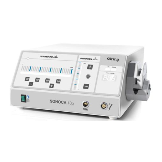
Overview Overview of the ultrasonic generator 3 Overview 3.1 Overview of the ultrasonic generator Fig. 3.1 Front Operator control panel for ultrasonic power Connector socket for an instrument Operator control panel for irrigation Connector socket for a foot switch Display panel Power switch Irrigation pump Ultrasonic Generator | DocNr.: 03-4655 R03.01 | 22.09.2015 | en-US... - Page 11 Overview Overview of the ultrasonic generator Made in 0123 Germany Söring GmbH Justus-von-Liebig-Ring 2 Tx.xAH D-25451 Quickborn Germany Funk / Radio Sonoca XXX Typ / Model: XXXXXXX 20XX SN XXXXXXX Spannung / Voltage: XXX V 50/60 Hz Netzanschluß Strom / Current: X.X A max Sicherung / Fuse: TX.XAH...
-
Page 12: Pictograms On The Ultrasonic Generator
Overview Overview of the ultrasonic generator 3.1.1 Pictograms on the ultrasonic generator Pictogram Meaning Read the instructions for use Type BF (classification in accordance with EN 60601-1) Instrument Foot switch High voltage High voltage warning Hazardous area warning Risk of entanglement warning Potential equalization Non-ionizing radiation Hazardous waste... -
Page 13: Serial Plate
Overview Overview of the ultrasonic generator 3.1.2 Serial plate The serial plate is attached to the back of the ultrasonic generator. Made in 0123 Germany Söring GmbH Justus-von-Liebig-Ring 2 D-25451 Quickborn Germany Typ / Model: Art. #.: Spannung / Voltage: Stromaufnahme / Current consumption: max. -
Page 14: Buttons And Indicator Lights
Overview Overview of the ultrasonic generator 3.1.3 Buttons and indicator lights Operator control panel for ultrasonic power Ultrasonic power can be increased and decreased on the operator control panel for ultrasonic power. Alternatively, the ultrasonic power can be selected directly. Ultra- sonic power can still be adjusted afterwards. - Page 15 Overview Overview of the ultrasonic generator Display panel The display panel provides information about the status of the ultrasonic generator and instrument activation time. The digital display shows the activation time (in minutes) of the connected instru- ment since the application was started. If a fault is detected during the self-test, a numeric code is displayed and the ERROR indicator light goes on.
-
Page 16: Scope Of Delivery
Overview Scope of delivery 3.2 Scope of delivery The ultrasonic generator comes without accessories. Performing a treatment requires an instrument and other accessories. Ultrasonic gen- erator accessories include: A foot switch A power cord A potential equalization cable (when using multiple medical electrical devices) ... -
Page 17: System Overview
Overview System overview 3.3 System overview The following instruments can be connected to the ultrasonic generator: Bone instrument 92-050 UAW handpieces 97-102, 97-103, 97-104, 97-112. These instruments are only activated by a single foot switch. The indicator light for in- strument activity goes on. -
Page 18: Transport And Storage
Transport and storage 4 Transport and storage For transport and storage of the ultrasonic generator, use packaging which protects it from damage and contamination. The storage environment must be dry, clean and dust-free. Storage temperature: between –20 °C and 50 °C (–4 °F and 122 °F) ... -
Page 19: Installation
Installation Connecting the ultrasonic generator to the main power supply 5 Installation The ultrasonic generator may only be put into operation by a qualified person who has been trained in the proper handling of it. Improper handling of the ultrasonic generator may lead to life-threatening situations or substantial material damage. -
Page 20: Connecting The Foot Switch
Installation Connecting the foot switch Requirements The actual power voltage corresponds to the output voltage shown on the serial plate. The ultrasonic generator is turned off; the power switch is set to '0'. Procedure 1. Connect the power cord to the connector socket on the back of the ultrasonic generator. -
Page 21: Turning On The Ultrasonic Generator
Installation Turning on the ultrasonic generator 5.3 Turning on the ultrasonic generator Refer to the instructions for use of the instrument and the accessory before starting the ultrasonic generator. After being turned on, the ultrasonic generator runs through a self-test. During the self-test, check that all indicator lights go on briefly. -
Page 22: Connecting Instruments
Installation Connecting instruments 5.4 Connecting instruments Before connecting an instrument to the ultrasonic generator first ensure via visual check that the instrument is in perfect working order. Connect the instrument cable first, then the irrigation tubing. It is important to con- nect the instrument cable and irrigation tubing to the instrument first and only after- wards to the ultrasonic generator. -
Page 23: Connecting The Irrigation Tubing To The Instrument
Installation Connecting instruments Requirements The ultrasonic generator is turned on. The instrument and instrument cable have been sterilized. Procedure 1. Insert the instrument cable into the connector socket on the instrument. Observe the markings. – The instrument cable engages in the connector socket. 2. -
Page 24: Connecting Irrigation
Installation Connecting irrigation 5.5 Connecting irrigation Install an irrigation bottle and connect the irrigation tubing already connected to the instrument to the irrigation. Fig. 5.1 Connection principle for irrigation Irrigation pump Spike and drip chamber Ultrasonic generator Irrigation tubing Irrigation holder Roller clamp Irrigation bottle Instrument... - Page 25 Installation Connecting irrigation Danger of crushing Rotating parts in the open irrigation pump may cause injury to fingers when the irri- gation tubing is being inserted. Do not reach inside the irrigation pump. 5. Open the irrigation pump. To do this, push the lever to the left. 6.
- Page 26 Installation Connecting irrigation 7. Insert the reinforced part of the irrigation tubing into the irrigation pump. Make sure the irrigation tubing is positioned below the locking clamps. 8. Close the irrigation pump. To do this, push the lever to the right. Ultrasonic Generator | DocNr.: 03-4655 R03.01 | 22.09.2015 | en-US...
- Page 27 Installation Connecting irrigation 9. Fix the irrigation tubing into place with both locking clamps. To do this, press on the locking clamps and slide them down. 10. Release the roller clamp on the irrigation tubing. – The irrigation tubing has been fixed in place. –...
-
Page 28: Operation
Operation Preparing for treatment 6 Operation Prior to initial and each subsequent treatment the ultrasonic generator must be cleaned and disinfected (see chapter 7 Reprocessing on page 35). Prior to each treatment functional testing of the ultrasonic generator must be per- formed and the ultrasonic generator's power settings must be checked (see chapter 6.1.2 Functional testing on page 29). -
Page 29: Functional Testing
Operation Preparing for treatment 6.1.2 Functional testing Prior to each treatment functional testing of the ultrasonic generator must be per- formed with the instrument being used. Ultrasonic power and irrigation flow on the ultrasonic generator must then be checked and adjusted. Requirements ... -
Page 30: Starting Treatment
Operation Starting treatment 6.2 Starting treatment Only personnel who have been properly instructed in the handling of the ultrasonic generator may begin treatment (see chapter 2.2 Selection and qualification of specialist staff on page 7). Handling the instrument Always use the instrument with care to prevent damage to the sonotrode. Do not bend the sonotrode or touch any metal objects with it. - Page 31 Operation Starting treatment Contaminated instruments The use of contaminated instruments may result in life-threatening infections in both patients and users. Use only a sterilized instrument. Only use a sterilized instrument cable. Use only sterilized accessories (irrigation tubing, cover). ...
-
Page 32: Ending Treatment
Operation Ending treatment 6.3 Ending treatment After treatment, the ultrasonic generator must be turned off. The instrument must then be disconnected and the accessories must be detached from the ultrasonic gen- erator. 6.3.1 Turning off the ultrasonic generator Procedure 1. Turning off the ultrasonic generator using the power switch. –... -
Page 33: Detaching The Irrigation Bottle
Operation Ending treatment 6.3.3 Detaching the irrigation bottle Requirements The ultrasonic generator is turned off. The instrument is disconnected from the ultrasonic generator and the irrigation system. The roller clamp on the irrigation hose is closed. Danger of crushing When the irrigation pump is open, rotating parts may injure fingers when the irriga- tion tubing is being removed. -
Page 34: Disconnecting The Ultrasonic Generator From The Main Power Supply
Operation Ending treatment 6.3.5 Disconnecting the ultrasonic generator from the main power supply Requirements The ultrasonic generator is turned off. Procedure 1. Disconnect the power cord from the main power supply and then from the ultra- sonic generator. 2. If required, disconnect the potential equalization cable from the potential equal- ization rail and then from the ultrasonic generator. -
Page 35: Reprocessing
Reprocessing Ending treatment 7 Reprocessing After each treatment the ultrasonic generator as well as all instruments and accesso- ries used must be cleaned and disinfected. All instruments and the instrument cable must then be sterilized. Reprocessing the instruments and the instrument cable is not described in these in- structions for use. -
Page 36: Cleaning The Ultrasonic Generator And Accessories
Reprocessing Cleaning the ultrasonic generator and accessories 7.1 Cleaning the ultrasonic generator and accessories Requirements The instrument cable is disconnected from the ultrasonic generator. The irrigation tube is disconnected from the ultrasonic generator and has been disposed of. ... -
Page 37: Preventive Maintenance
Preventive maintenance Faults 8 Preventive maintenance Maintenance of the ultrasonic generator entails checking the condition of the ultra- sonic generator and the extent of wear at regular intervals. Once per year, have an ex- pert perform a safety check of the ultrasonic generator You can remedy some faults occurring during the self-test or in operation yourself. -
Page 38: Faults Occurring During Operation
Preventive maintenance Faults 8.1.2 Faults occurring during operation During operation, other faults which can be attributed to other influencing factors may occur. Notification of faults detected by the ultrasonic generator is provided in two ways: An alarm tone sounds. The ERROR indicator light goes on. -
Page 39: Safety Check
Preventive maintenance Safety check 8.2 Safety check A safety check of the ultrasonic generator must be performed once a year. The safety check may only be performed by qualified personnel authorized by the manufacturer using suitable measuring and testing devices. The type and scope of the safety check are prescribed by the manufacturer. -
Page 40: Disposal
Disposal 9 Disposal If the ultrasonic generator or accessory has reached its end of life, you must ensure its proper disposal. An improperly disposed of ultrasonic generator or improperly dis- posed of accessory may cause damage to the environment. Give the ultrasonic generator or accessory to a disposal company. You can also send in the ultrasonic generator to the manufacturer or an authorized distributor for dis- posal. -
Page 41: Technical Data
Technical data 10 Technical data SONOCA 185 Dimensions: Width: 370 mm, height: 160 mm, depth: 390 mm Weight: 13.0 kg Output voltage: 230 V ± 10% 115 V ± 10% 100 V ± 10% Current consumption: max. 0.6 A max. 1.2 A max. -
Page 42: Electromagnetic Compatibility
Electromagnetic compatibility 11 Electromagnetic compatibility The ultrasonic generator meets the requirements of IEC 60601-1-2 for electromag- netic compatibility. Ultrasonic Generator | DocNr.: 03-4655 R03.01 | 22.09.2015 | en-US... - Page 43 Electromagnetic compatibility DocNr.: 03-4655 R03.01 | 22.09.2015 | en-US | Ultrasonic Generator...
- Page 44 Electromagnetic compatibility 11.1 Ultrasonic Generator | DocNr.: 03-4655 R03.01 | 22.09.2015 | en-US...
-
Page 45: Index
Index Index Contamination, see Cleaning Accessories cleaning 36 Digital display 15 disinfecting 36 disposing of 40 Disinfection 36 reprocessing 35 Display Activation tone 28, see also Alarm tone for the irrigation flow 14 for ultrasonic power 14 Adjusting the irrigation flow 14 Display panel 10, 15 ultrasonic power 14 Disposable accessories, disposing of 35... - Page 46 Index Instructions for use, see Instructions for use Overview 10 for the instruments 5 for the ultrasonic generator 5 purpose of the 5 Packaging 18 Instrument Pictogram contaminated 31 foot switch 12 disconnecting from the ultrasonic generator 32 hazardous waste 12 not working 38 high voltage 12 reprocessing 35...
- Page 47 Index Specialist staff, qualified 7 Ultrasonic generator cleaning 36 Spike 24 conditions for handling 6 Start-up 19, 21 connecting to the main power supply 19 defective 39 Storage 18, see Storage disinfecting 36 Storage environment 18 disposing of 40 irreparable 39 System overview 17 overview of 10 reprocessing 35...
- Page 48 Index Ultrasonic Generator | DocNr.: 03-4655 R03.01 | 22.09.2015 | en-US...
- Page 50 Söring GmbH Justus-von-Liebig-Ring 2 D-25451 Quickborn Tel.: +49 (0)4106-6100-0 Fax: +49 (0)4106-6100-10 Content management Email: info@soering.com ZINDEL AG Internet: www.soering.com www.zindel.de...
Need help?
Do you have a question about the SONOCA 185 and is the answer not in the manual?
Questions and answers