
Related Manuals for Hiltron security PROTEC4GSM


Summary of Contents for Hiltron security PROTEC4GSM
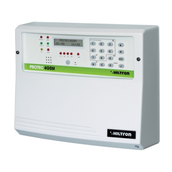
- Page 1 PROTEC4GSM PROTEC8GSM Centrale 4/8 zones with dialing pad GSM and incorporated detector INSTALLATION GUIDE AND USE...
- Page 2 PROTEC4GSM - PROTEC8GSM - Installation guide and use security Introduction Features Antitheft alarm, two delayed locations + two ready locations (6 for PROTEC8GSM)+phone line 4 cabled hubs (8 for PROTEC8GSM) or singularly programmable radio hubs. Management of two RF optional transceivers for the radio signals of the peripheral devices series XR, until two DXR1 (external), connected on the bus RS485, or a DXR1 and a DXR2 that is positioned in the switchboard on a dedicated base.
- Page 3 Introduction security Technical Characteristics PROTEC4GSM PROTEC8GSM Immediate Protection Zones Delayed Protection Zones Tamper protection zones “24” h 1 + Tamper Maximum absorption (central computer only) 65mA@230Vac Total power supplied from the power source 35W (2,6Ah a 13,5V) Compartment for buffer battery Battery B 12V7.5 Ah...
- Page 4 PROTEC4GSM - PROTEC8GSM - Installation guide and use security Installation General instructions Do not install the central computer in extreme hot places or expose to bad weather. In order to fix it safely and strongly it is appropriate to make sure to mount it on a flat surface.
- Page 5 Installation security Installation of the anti theft Tamper Drill a hole in correspondence with the placeholder on the base of the container and insert the plug supplied. Tighten the screw leaving protrude from the mounting surface as required in order to keep the tamper contact closed (6-10 mm).
- Page 6 PROTEC4GSM - PROTEC8GSM - Installation guide and use security Description of the board EASY-CONNECT Once the connections are completed, insert the two conductors equipped with faston type connector from the feeder to the battery, respecting the polarity of connection. Red= [+] positive battery / Black= [-] negative battery WARNING! In order to let operate the system correctly, the battery must always be connected.
- Page 7 2.4.1 Easy-Connect System The new system Easy-Connect, used in the central computers PROTEC4GSM and PROTEC8GSM, it was projected to ease the installation and the maintenance of the system. The circuit of the central is divided into two boards: A-The board of connections / fuses.
- Page 8 PROTEC4GSM - PROTEC8GSM - Installation guide and use security 2.4.2 onnecting volumetric detectors and contacts SIR +12v Manutenzione Centrale A B -12V+ +INT GND 24H GND Z1 Z2 Z3 Z4 Z5 Z6 Z7 Detector Z3 Logic Resistor 3300ohm Long Short...
- Page 9 GND Z1 Z2 Z3 Z4 Z5 Z6 Z7 in series ti the 24H line Electronic siren Self-powered NOTE: On the burglar alarm PROTEC4GSM and siren PROTEC8GSM, when you are using the radio module DXR1/DXR2, it is possible to use the sirens XR300.
- Page 10 If you are using a DXR1 in addition to the DXR2, it is necessary to programme it with the address 33. The central computers PROTEC4GSM and PROTEC8GSM can accept transceivers with address 32 or 33 and it can't accept devices with a doubled address.
- Page 11 Installation security DXR2 Internal board Receiver 1 Address 32 – fixed SIR +12v Manutenzione NOTE: The transceiver DXR2 must be inserted with the Centrale components face-down A B -12V+ +INT GND 24H GND Z1 Z2 Z3 Z4 Z5 Z6 Z7 Receiver 1 DXR1 ADDRESSE 32...
-
Page 12: Table Of Contents
Add. 18 ADDRESSE 18 Reader 4 DX300 Ind. 18 Add. 19 ADDRESSE 19 NOTA PROTEC4GSM and PROTEC8GSM manageo until 4 readers that must beconfigured invidually through dip-switch . Make sure not to use the same address on more devices. WARNING: WARNING:... -
Page 13: A B -12V+ +Int Gnd 24H
Installation security 2.4.6 Connection of the console Dx22 DXR2 SIR +12v NOTE: The transceiver DXR2 must be inserted with the components face-down. Manutenzione Centrale A B -12V+ +INT GND 24H GND Z1 Z2 Z3 Z4 Z5 Z6 Z7 CONSOLE ADDRESSE 8 DX22 A + - WARNING:... -
Page 14: Key Sir Gnd S.a
PROTEC4GSM - PROTEC8GSM - Installation guide and use security 2.4.7 Connections with the traditional electronic key DXR2 NOTE: The transceiver DXR2 must be SIR +12v inserted with the components face-down. Manutenzione Centrale A B -12V+ +INT GND 24H GND Z1 Z2 Z3 Z4 GND... -
Page 15: Warning
Installation security 2.5 Connecting the console board/cpu Once finished the connections on the board Easy-Connect, it is possible to reconnect the console board/CPU. Use the multipolar flexible cable and verify to insert it in the board on the bottom of the container on the central connector JX1. - Page 16 PROTEC4GSM - PROTEC8GSM - Installation guide and use security Programming It is possible to interact with the central computer from the console using the panel through the menu: -Programming menu: you can access by entering the code SETUP ( of default) in order to program and for the operating parameters of the central computer.
-
Page 17: Use The
Programming security 3.1.2 Telephone book Entering telephone numbers Once you enter the program menu, press to visualize. T E L E P H O N E B O O K E n t e r t e l e p h o n e n u m b e r s Press . - Page 18 PROTEC4GSM - PROTEC8GSM - Installation guide and use security 3.1.3 Deleting telephone numbers In order to delete a telephone number, enter the menu “Telephone book” and press the buttons until you put in evidence: T E L E P H O N E B O O K...
- Page 19 Programming security Setup Enter the program menu and dial or use the buttons in order to visualize: I n s t . D i s c o n n e c t e d 2 - S e t u p And press Writes key - Write the memorized code in the central computer on a key.
-
Page 20: Reader
PROTEC4GSM - PROTEC8GSM - Installation guide and use security 3.2.1 Write key This function allow to writ in the keys DXK, PX and KEY the code of the central unit. To select the first voice : W r i t i n g K e y... - Page 21 Programming security 3.2.3 NEW KEY CODE Through this function it is possible to substitute the memorized code in the central computer with a different one automatically generated. Select the function N e w K e y C o d e And press The display will show the following message: G E N E R A T E D C O D E...
- Page 22 PROTEC4GSM - PROTEC8GSM - Installation guide and use security 3.2.6 Entrance Timing The entrance timing in is the time the user takes to come to the protected environments and disconnect the system before the alarm signals activate. During this time, a possible detection of the sensors on the protection zones delayed (zone 1 and 2) won't activate alarms and won't activate the alarm memory.
- Page 23 Programming security 3.2.8 Alarm Duration The duration of the BEEPS both on the sirens and on the key readers DX300 (if enabled) can be set between 180 and 600 seconds (from 3 to 10 minutes). The duration of the alarm signals 24h when the system is disconnected is fixed at 180 seconds. In the SETUP menu select: A l a r m D u r a t i o n 1 8 0...
- Page 24 PROTEC4GSM - PROTEC8GSM - Installation guide and use security 3.2.10 Logical zones / balanced / radio This option allows you to change the functioning of the entrances of the zones and to signal the radio zones. Select this option from the SETUP menu with the buttons Z o n e L o g / B a l / R f >...
- Page 25 Programming security 3.2.11 Ir on delayed zone This option enables the infrared detector that is on the panel in order to alarm the zone 1 (delayed): Select: O n D e l a y e d Z o n e D i s a b i l i t a t o In order to change the status, press the button O n D e l a y e d z o n e 1...
- Page 26 PROTEC4GSM - PROTEC8GSM - Installation guide and use security 3.2.13 Enabling with input key Allows to set what kind of insertion will be carried out with a pulse on the terminal “KEY”. Select: E n t e r I n p u t K e y...
- Page 27 Programming security 3.2.15 Volume of the beep on the inserting dx300 This option is used to set the intensity of the beep generated by the inserting DX300 when a key must be recognized. In the menu, select B e e p I n s e r t e r >...
- Page 28 PROTEC4GSM - PROTEC8GSM - Installation guide and use security 3.2.18 RADIO Code The code of 18 binary digits (a sequence of 0 and 1) that is possible to program and visalize in this section is that one used from PROTEC8GSM and that has to be to set in all the radio devices that have to be connected to the central computer.
- Page 29 Programming security 3.2.19 Devices 485 The devices connected on the bus 485 must be enabled to allow the management of the central unit. Select the option : D e v i c e s 4 8 5 Press with the buttons select the device to enable o disconnect and press to modify the setting.
- Page 30 PROTEC4GSM - PROTEC8GSM - Installation guide and use security 3.2.20 Devices (CONNECTORS) Devices connected on the bus 485 must be enabled to allow for operating on the central unit. Select the option : D e v i c e s 4 8 5...
- Page 31 Programming security 3.2.21 Connectors Activation Devices connected on bus 485 must be configured to allow the manage on the central unit. To select the option : C o n n e c t o r 1 N O T A C T I V E And press With bottons to select the device to enable or disable and press...
- Page 32 PROTEC4GSM - PROTEC8GSM - Installation guide and use security 3.2.22 Devices 24 H 485 It is possible to compel the central computer to generate a cycle of alarm 24h when the communication on a device connected on the bus 485 is interrupted. To activate/disconnect this function select the buttons...
- Page 33 Programming security 3.2.24 Forwarding SMS If enabled, the combiner sends all the received SMS to the inserted number in the position number 1 of the phonebook. F o r w a r d i n g S M S C o n n e c t e d For status change , press the buttons F o r w a r d i n g S M S...
- Page 34 PROTEC4GSM - PROTEC8GSM - Installation guide and use security Info In the programming menu use the buttons until you visualize: I n s . D i s c o n n e c t e d 3 - I n f o...
- Page 35 Programming security ERASE Setup In the Programming menu press until you visualize: I n s . D i s c o n n e c t e d 5 - E r a s e S e t u p and press the button , or dial directly the SETUP code followed by The central computer requires to confirm to erase:...
- Page 36 PROTEC4GSM - PROTEC8GSM - Installation guide and use security Initial Message The initial message is a short audio message regitered by the user that can be useful to detect from what system is coming an alarm call. In the Programming menu use the buttons in order to select: I n s .
- Page 37 Programming security Commands Enter the menu commands 8 8 4 8 8 4 When the system is connected or disconnected dial the user code (default followed by in order to enter the menu commands. The first option of the menu that appears depends on the status of the central computer. When the system is disconnected appears on the display: 3 1 Y v o d a I T 7 - T o t a l E n t r y...
- Page 38 PROTEC4GSM - PROTEC8GSM - Installation guide and use security USER Code Allows to modify the USER CODE that allows to enter the commands menu. Select : I n s . D i s c o n n e c t e d...
- Page 39 Programming security Activation OUT Select in the Programming menu: I n s . D i s c o n n e c t e d 6 A c t i v a t . O U T Then dial O U T : D i s c o n n e c t e d 7 = O N 9 = O F F Press...
- Page 40 PROTEC4GSM - PROTEC8GSM - Installation guide and use security Partial Insertion A and Partial b When the central computer is disconnected, select the commands menu: I n s . D i s c o n n e c t e d 8 P a r t .
- Page 41 Programming security Voice Menu The central units PROTEC4GSM and PROTEC8GSM are endowed of a menu with a voice guidance to be used both locally and from a remote controller through the GSM connection. 5.1 Access from the central panel Press the button...
- Page 42 PROTEC4GSM - PROTEC8GSM - Installation guide and use security Leading voice Once you access the voice menu, the leading voice provides you with the indications of the status of the central: <Alarm system>, or <Alarm 24h> if the central is carrying out an alarm.
- Page 43 Programming security 5.3.1 Commands of the voice Menu 0- DISCONNECT This command is listed when the central is connected only and it is useful to disconnect the central. After the execution of the command the voice guide indicates a new status of the central <System disconnected>...
- Page 44 PROTEC4GSM - PROTEC8GSM - Installation guide and use security 5 - LISTENING ENVIRONMENT Listening environment is allowed during the phone connection only. Dial to activate it and to close it. If you wish to extend the duration of listening for more than a minute, you'll need to dial any button (but ) to extend the duration of listening for another minute.
- Page 45 LED “GSM” A fast flashing every 3 seconds Modulo GSM registrato sulla rete Others flashing Attività GSM LEDs di controllo stato (4 per PROTEC4GSM), (8 per PROTEC8GSM) zone e 24h Acceso Zona aperta Spento Zona chiusa Un lampeggio veloce ogni secondo Zona esclusa Acceso con uno spegnimento veloce ogni sec.
- Page 46 PROTEC4GSM - PROTEC8GSM - Installation guide and use security Reports on display During the normal functioning of the central, it provides some information on the display of the panel and of the consolle related to the status of the system, and the GSM Module.
- Page 47 Use of the central unit security STATUS OF THE SYSTEM OPEN ZONES On the second line of the display are indicated the open zones. The leds of the open zones on the panel of the central computer are turned on. Pay attention: the signal of the opening of the radio zones lasts 2 seconds.
- Page 48 PROTEC4GSM - PROTEC8GSM - Installation guide and use security 6.3 - Commands 6.3.1 - INSERTING THE SYSTEM From the panel of the central it is necessary to verify that the immediate zones aren't open: check that the related LEDs aren't active and eventually close doors and windows or leave the environments to be sorveilled by the sensor that keep the zone in alarm.
- Page 49 Use of the central unit security Toconnect the installation from the panel of the central unit, by using the guide from voice menu , dial to activate the guide and,following the indications to insert the code and then dial for total connection , to connect the partial A installation.
- Page 50 PROTEC4GSM - PROTEC8GSM - Installation guide and use security 6.3.2 Disconnection From the panel or from console it’s necessary dial the USER code, to select the menu : I n s . D e s a b l e d...
- Page 51 Use of the central unit security 6.3.4 Activation exit When the exit is programmed to operating to “Command ON/OFF” (see the paragraph 3.3.21) it’s possible to command the exit from the panel and from the console or from the telephone. Dial on thje panel of the central unit the USER code followed by On the display appear: O U T : D i s a c t i v e...
- Page 52 PROTEC4GSM - PROTEC8GSM - Installation guide and use security 6.4 Operating of the zones The entry zones can be wired type (logic or balanced) or radio. A line of entry configured like logic is defined alarmed when doesn’t closed to GND that is when the sensor placed on the line not short-circuited the block terminal of entry of the zone (Z3 for example) with one of the terminal blocks common GND.
- Page 53 Use of the central unit security 6.4.2 Immediate zones When the installation is connected ,the activation of a immediate zone (3 e 4) starts immediately a round of alarm of the central unit . 6.4.3 Zone 24h When the installation is disconnected the activation of the line 24h on thje wired line,for openging of tamper of the central unit , of the console, or to signalisation of a radio detector, starts a round of alarm of the duration of 3 minutes.
- Page 54 6.4.5 Exclusion zones It’s possible to exclude one o more zones from the monitoring of the central unit PROTEC4GSM. With central unit connected to need access to Commands Menu (Dialing the USER code followed by ) and to dial the correspondent button to the zone to exclude/include again.
- Page 55 Use of the central unit security 6.5 Operating of the comunication GSM. On the first line of display of the central unit are visualized the indications on the status of the GSM dial If the display visualize: I n s e r i r e S I M I m p D i s i n s e r i t o It’s necessary introduce a SIM card phone.
- Page 56 PROTEC4GSM - PROTEC8GSM - Installation guide and use security During the connection on the display appear the indication : C o n n e c t e d ..and sendign the USER code with tones DTMF: C o n n e c t e d .
- Page 57 Use of the central unit security 6.5.1 Remote Control During a phone connection,it’s possible to command the central unit sending the tones DTMF from the phone pad. The activtion of the remote control can occur or during a call alarm of the central unit or calling directly tne number of the SIM of the central unit.
- Page 58 PROTEC4GSM - PROTEC8GSM - Installation guide and use security ELECTRONIC KEY DX100 With the readers DX100 it’s possible to read the PX keys and to execute following operations: - To connect the installation into modality TOTAL, PARTIAL A and PARTIAL B.
- Page 59 Use of the central unit security TOTAL CONNECTION 1 - To approach the key to the reader Exit Time 2 - When the led visualize the correct recognition Green Led (Valid Key) to get away the key to connect the installation. Red Led The Led will visualize the temporisation of EXIT.
- Page 60 PROTEC4GSM - PROTEC8GSM - Installation guide and use security 6.6.2 Others signalisations on the connector Green Led Red Led Alarm installation: 1 sec. Green Led Red Led Alarm memory to the central unit disconnected : 1 sec. Green Led Red Led 1 sec.
- Page 61 Use of the central unit security 6.7 Proximity reader DX300 With the readers DX300 it’s possible to read the keys "KEY" and to execute following operations: - Connect installation in the TOTAL, PARTIAL A and PARTIAL B mode. - Diconnect installation. - To read or to write new keys "KEY"...
- Page 62 PROTEC4GSM - PROTEC8GSM - Installation guide and use security letter "i" - Installation connected "d" with 2 alternate points + "8". Alarm 24H to the central unit disconnected. "E" with 2 alternate points + "8". - Alarm 24H to the central unit disconnected with excluded zones .
- Page 63 Use of the central unit security 6.7.2 Use of key Total mode connection When the central unit is disconnected ( <d> or <E> on display) to approach the key to the connector: the buzzer on the corrector emit a beep . Get away the key from the connector: the buzzer of the connector emit three beep and the connector send the connection total command of the installation.
- Page 64 Use of the central unit security Error addressing If the central unit doesn’t recognize the addresse configured on the connector or on the central unit doen’t enabled the same connector between the devices 485, on display appear the animation : Privacy mode If you program on the central unit that the connector have to hide the informations (Setup->Privacy Connector = N),the display of the connector shows the flashing point down and doesn’t signal opened or excluded zones or...
Need help?
Do you have a question about the PROTEC4GSM and is the answer not in the manual?
Questions and answers