
Related Manuals for BLUM PRO-CENTER


Summary of Contents for BLUM PRO-CENTER
- Page 1 Blum PRO-CENTER Please keep a copy of the instruction leaflet. The instruction leaflet contains the EC Declaration of Conformity, which must be produced for authorities upon request. BA-077/1EN M6X.20XX...
-
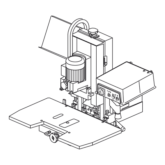
Page 2: A- Orientation Diagram
A- Orientation diagram Fixing screws (4pcs M8x80) Handles Crane eye Controller D11 Hexagonal Allen key screws (4pcs M8x20) E29 Stop screw for drilling depth revolver (M8x30, M8x40, M8x50) E30 Adjustable depth stop rod (3psc) Allen key 4 with cross handle Allen key 6 Allen key 4 Spanner SW10/13 (2psc) - Page 3 A- Orientation diagram Work table Controller Extraction port Air filter unit E16 Drill head depth stop E17 Drill head depth adjuster E18 Set screw (head brake) E19 Mode switch (Vertical drilling and/or drilling and insertion) Work top Controller Extraction port Air filter unit E16 Revolving handle (drilling depth) E17 Revolver (drilling depth)
-
Page 4: Table Of Contents
D.6 - Dust emission E - EC Declaration of Conformity E.1 - EC Declaration of Conformity E.2 - Technical data 2 - Setting up PRO-CENTER 2.1 - Unpacking and assembly 2.2 - Connecting to compressed air system 2.3 - Electrical connection 2.4 - Dust extraction... -
Page 5: C - Reading Guide
Dear valued Blum customer, We would like to congratulate you on your decision to purchase the Blum assembly machine. You are now the owner of a modern, high-quality assembly machine that will give you years of productive use with the proper care and maintenance. -
Page 6: D - Safety Information
D - Safety information D.1- Remaining risks according to ISO EN 12100-2 • This machine complies with current safety standards. However, there are remaining risks. • In the event of either pneumatic or electrical component failure ,it may be possible for the machine to make an unintended movement .for this reason safety guards should never be removed. -
Page 7: Noise Emission
• Make sure that no other tools or objects are on the work table aside from your work piece before turning on the assembly machine. • Always turn the main switch (E1) to POS. 0 after finishing work • CAUTION: For your own safety, use only those accessories which are recommended or indicated in the manual or Blum sales literature. -
Page 8: E - Ec Declaration Of Conformity
E - EC Declaration of Conformity E.1 - EC Declaration of Conformity Julius Blum GmbH, Industriestr. 1, A-6973 Höchst herewith declare on our own responsibility that the product PRO-CENTER (M60.20xx and M65.20xx) with drilling heads (MZK.2000, MZK.2100, MZK.2110, MZK.2200, MZK.2210, MZK.2230, MZK.2400, MZK.2410, MZK.2800, MZK.2810, MZK.2880) to which this Declaration refers, complies with the following EC Directives:... -
Page 9: Setting Up Pro-Center
2 - Setting up PRO-CENTER 2.1 - Unpacking and assembly 2.1.1) PRO-CENTER space requirement • PRO-CENTER without horizontal drilling unit Height H = 890 B = 1000 D = 700 • PRO-CENTER with horizontal drilling unit Height H = 890... - Page 10 2 - Setting up PRO-CENTER b) If using a crane, the crane hooks (D3) should be used to lift the machine. • Secure the machine to the work top using the fixing screws (D1) Important A horizontal drilling machine should not rest on the table so that the wood chips can fall downward 2.1.5) Attaching the controller...
-
Page 11: Connecting To Compressed Air System
2 - Setting up PRO-CENTER 2.1.8) Attaching (D5) work table • Place work table (D5) on the machine foot • Secure work table (D5) using the included hexagonal Allen key screws (D11) 2.1.9) Removing crane eye (D3) • Unscrew the crane eye 2.2 - Connecting to compressed air system... -
Page 12: Dust Extraction
(D7) is not encumbered 2.4.2) Attaching the extraction system to the controller of PRO-CENTER 2000 ATTENTION The electrical connection must be performed by a qualified electrician! • In order for the machine to be operated only with the extraction system turned on, terminals 12 and 18 (see electrical diagram) must be connected to a potential-free contact of the dust extraction controller. -
Page 13: How To Operate The Machine
3 - How to operate the machine 3.1 - Description of operator panels 3.1.1) Designation of operating elements • (E1) ... Main switch= Emergency off switch • (E2) ... Mode switch • (E3) ... Start button • (E4) ... Hold down clamp switch •... -
Page 14: Vertical Drilling Unit
3 - How to operate the machine 3.2 - Vertical drilling unit 3.2.1) Gearbox replacement at Pos. I • Main switch (E1) • Mode switch (E2) at Pos. symbol (setup) • Loosen locking device (E7) by turning to the left •... - Page 15 3 - How to operate the machine • Loosen ruler clamping screws (E8) until the stop • Pull ruler forward and remove from the top • Place ruler in the storage rack ruler holder. • Insert desired ruler (E9) into the specified elongated hole with the indexing pegs and slide all the way back.
- Page 16 3 - How to operate the machine b) Setting via calibration • Loosen the clamping lever (E10) • Pull out work table completely • Set revolving handle (E11) to position "H" • Set the work table using the calibration • Retighten the clamping lever (E10) 3.2.4) Setting hold down clamps (E14)
-
Page 17: Vertical Drilling And Fittings Insertion
3 - How to operate the machine 3.3 - Vertical drilling and fittings insertion 3.3.1) Assembly of furniture hinges, furniture connectors, METABOX front fixing brackets, etc. • Insert the gear box (see chapter 4 Gearbox replacement) • Attach ruler • Set work table (E11) Important Particular care must be taken when working on sections that jut out... -
Page 18: Vertical Drilling Only
3 - How to operate the machine 3.3.4) Drilling ATTENTION Make sure that only the work piece is in the working area of the ma- chine. Keep your hands out of working area of the machine during drilling and insertion. •... -
Page 19: Pre-Setting Revolver For Drilling Depth
3 - How to operate the machine 3.4.2) Switch settings on the operator panel • Turn on extraction system to Pos. I • Set main switch (E1) • Set mode switch (E2) to Pos. I (operation) • Set hold down clamp (E4) to Pos. -
Page 20: Pre-Setting Revolver For Work Top Setting
3 - How to operate the machine 3.5.2) Setting the stop dimension • Select a suitable screw (E29) depending on the desired drilling depth • Turn screw to the desired dimension Z in the drill and lock using the counter nut a) Drilling depth Work piece thickness >... -
Page 21: Horizontal Drilling Unit
3 - How to operate the machine 3.6.4) Setting the stop rod to the exact dimension • Set the work top to the desired drilling position using the calibration • Retighten the clamping lever (E10) • Unscrew stop rod to the stop and lock using the counter nut •... - Page 22 3 - How to operate the machine 3.7.2) Setting the work table for horizontal drilling • Loosen the clamping lever (E10) • Pull out work table completely • Set revolving handle (E11) to position “H” • Slide work top to the stop •...
- Page 23 3 - How to operate the machine 3.7.6) Setting the drilling distance (rough setting) • Loosen the horizontal drilling unit clamping screw (E23) • Set the desired dimension by turning the adjustment screw (E24). (Dimension can be read directly from the calibration (E25)) •...
- Page 24 3 - How to operate the machine 3.7.9) Drill bit change • Insert horizontal ruler • Press in locking mechanism (E22) • Push up horizontal ruler holder (E21) until it locks. Note Both control lights flash. • Loosen clamping screw (E26) •...
-
Page 25: Horizontal Drilling
3 - How to operate the machine 3.8 - Horizontal drilling 3.8.1) Drilling side holes • Insert the horizontal ruler • Set work top to Pos. “H” (E11) Important Particular care must be taken when working on sections that jut out over the work table. - Page 26 3 - How to operate the machine Drilling ATTENTION Make sure that only the work piece is in the working area of the ma- chine. Keep your hands out of working area of the machine during drilling and insertion. • Press the start button (E3) until the drilling depth is reached - The vertical drilling unit moves downward and the horizontal hold down clamp...
-
Page 27: Working With Pro-Center
4 - Working with PRO-CENTER 4.1 - Creating a setup plan Note To better understand the following description and procedures, take a look at the included sample setup plan. 4.1.1) Identifying drilling head and ruler • In the overview on pages 38 and 39, select the required gearbox and ruler for the desired assembly application. - Page 28 4 - Working with PRO-CENTER 4.1.4) Inserting the drilling head into the PRO-CENTER • Add the colour description for the selected drilling head to the setup plan • In the fields ... Drilling ... Drilling and insertion check whether or not mode switch (E19) is set to vertical drilling or vertical drilling and fittings insertion.
-
Page 29: Overview (Assembly - Drilling Heads - Rulers)
4 - Working with PRO-CENTER 4.2 - Overview (assembly - drilling heads - rulers) BA-077/1EN M6X.20XX... - Page 30 4 - Working with PRO-CENTER Drilling head Ruler hinge Dowel mounting plates Cruciform mounting plate cabinet profile System drilling Drilling head Ruler dowel cabinet connec- cabinet connec- cabinet connec- METABOX front fixing bracket BA-077/1EN M6X.20XX...
-
Page 31: Drilling Heads Overview
4 - Working with PRO-CENTER 4.3 - Drilling heads overview 4.3.1) General a) Storing drilling heads • Attach drilling head holder to a wall, table or the storage rack b) Setting drill bit length Important The total length of the drill bits (from bit-tip to adjustment screw) must... - Page 32 4 - Working with PRO-CENTER 4.3.2) FH drilling head: MZK 2000 a) Furniture hinge drilling head for standard hinges • Drilling head with 3 spindles • With 13mm depth stop • Swing arm for ram attachment • Drill bits: ... 2 x Ø...
- Page 33 ... 1 x Ø 10 mm Clockwise • Colour coded bits: Counter clockwise = red Clockwise = black 4.3.6) SYH drilling head: MZK.2200.01 for all Blum cabinet profiles • Drilling head with 8 spindles • Drill bits: ... 4 x Ø 5 mm Counter clockwise ...
- Page 34 4 - Working with PRO-CENTER 4.3.8) BOX drilling head: MZK.2230 for all METABOX front fixing brackets and back fixing positions • Drilling head with 5 spindles • With drilling depth stop • Swing arm for ram attachment • Drill bits: ...
-
Page 35: Rulers Overview
4 - Working with PRO-CENTER 4.4 - Rulers overview 4.4.1) General a) Attaching rulers • Installing ruler holders to the work top: - Attach a ruler holder to the work top surface. - Attach the second to the floor - Place the ruler vertically into the lower holder and clip into the top holder. - Page 36 Important Make sure that the calibration on the ruler support corresponds to the one on the work table of the PRO-CENTER 2000. Pay attention to the adjustment area of the work table. • Before setting the work table, loosen the clamping lever on the ruler support. Then retighten.
-
Page 37: Maintenance And Service
5.1.2) Replacing a damaged gearbox coupling ATTENTION Replace broken or damaged parts immediately. Only use Blum original parts. • Use a flathead screwdriver to remove the damaged coupling • Slip the replacement coupling onto the shaft until it aligns with the shaft at the top... -
Page 38: Troubleshooting
6 - Troubleshooting 6.1 - What do the individual flashing signals mean? Error Cause Solution Note Control light for Gearbox is not clamped properly Tighten the drilling head locking See chapter 3 vertical drilling device(E7) until the control light stops flashes quickly flashing Control light for... -
Page 39: Error During Vertical Drilling
6 - Troubleshooting 6.2 - Error during vertical drilling Error Cause Solution Note Drilling depth does Drilling depth revolver is set to the Set the drilling depth revolver to the correct See chapter 3 not match wrong position work piece thickness Drill bits are set too short or too long Drilling length set to 57 mm See chapter 4... - Page 40 6 - Troubleshooting Error Cause Solution Note Drilled holes too Drill diameter is too large Check drill bits none large, oval or rag- Drill bits are twisted Replace drill bits none Drill bits are dull Repoint drill bits or replace none Head speed for drilling is too high Set proper head brake point...
-
Page 41: Error During Horizontal Drilling
6 - Troubleshooting 6.3 - Error during horizontal drilling Error Cause Solution Note Drilling depth not Drilling depth was not set correctly Set correct drilling depth See chapter 3 reached Drilling length does not match Drilling length should be 77 mm none Drill bits not completely inserted into Clean chuck and/or use cover caps if no... -
Page 42: Diagrams
7 - Diagrams 7.1 - Electrical diagram 1x230 V 50 Hz BA-077/1EN M6X.20XX... -
Page 43: Electrical Diagram 3X400 V 50 Hz
7 - Diagrams 7.2 - Electrical diagram 3x400 V 50 Hz BA-077/1EN M6X.20XX... - Page 44 7 - Diagrams 7.3 - Electrical diagram BA-077/1EN M6X.20XX...
-
Page 45: Pneumatic Diagram
7 - Diagrams 7.4 - Pneumatic diagram BA-077/1EN M6X.20XX... - Page 46 PRO-CENTER 2011 Ser.No.: AK 00001 kg / Bohr- und Beschlagsetzmaschine Ref.No.: M65.2000 Julius Blum GmbH - A - 6973 RU Сверлильно-присадочный станок BG Пробивни машини Bore- og beslagssætmaskiner Bohr- und Beschlagsetzmaschine Drilling and insertion machine Puurimis- ja sisestusmasinad Asennusporakoneet Machine pour percer et poser des ferrures EL Μηχάνημα διάτρησης και τοποθέτησης...
- Page 47 Notes BA-077/1EN M6X.20XX...
- Page 48 Julius Blum GmbH Beschlägefabrik 6973 Höchst, Austria Tel.: +43 5578 705-0 Fax: +43 5578 705-44 E-Mail: info@blum.com www.blum.com...
Need help?
Do you have a question about the PRO-CENTER and is the answer not in the manual?
Questions and answers