Table of Contents
Advertisement
Quick Links
S
O
L
I
D
S
O
L
I
D
L
B
W
-
4
2
L
B
W
-
4
2
L
B
W
-
4
2
L
B
W
-
4
2
L
B
W
-
4
2
L
B
W
-
4
2
M
o
M
o
S
T
A
T
E
S
T
A
T
E
0
-
3
-
S
S
(
1
0
-
3
-
S
S
(
1
0
-
1
-
S
S
(
2
0
-
1
-
S
S
(
2
0
-
2
-
S
S
(
2
0
-
2
-
S
S
(
2
d
e
l
s
d
e
l
s
S
E
N
S
O
R
S
E
N
S
O
R
1
5
V
A
C
1
5
V
A
C
4
V
D
C
p
4
V
D
C
p
3
0
V
A
C
3
0
V
A
C
Solid State Sensor
O
N
L
Y
O
N
L
Y
p
o
w
e
r
e
d
p
o
w
e
r
e
d
o
w
e
r
e
d
)
o
w
e
r
e
d
)
p
o
w
e
r
e
d
p
o
w
e
r
e
d
)
)
)
)
Advertisement
Table of Contents

Related Manuals for Cool Air LBW-420-1-SS


Summary of Contents for Cool Air LBW-420-1-SS
- Page 1 Solid State Sensor...
-
Page 3: Table Of Contents
P ................18 N .............. 19 ............. 19 ..20 ..................21 4-20 ..............21 ROGRAMMING THE RANGE ............22 ............23 ..................... 24 Rev. 10-0 8-1-2018 Page | 1 Copyright © 2018 by Cool Air Incorporated. All rights reserved. - Page 4 24 Volts DC, 21.6 – 26.4, +/- 10% 0.5 Amps max. Dimensions 9½” H x 8” W x 4½”D Weight 6 lbs. Enclosure NEMA 4X rated, UL listed Rev. 10-0 8-1-2018 Page | 2 Copyright © 2018 by Cool Air Incorporated. All rights reserved.
-
Page 5: I M P O R T A N T - R E A D T H I S F I R S T
After applying power, test the detector to ensure it is operating correctly. Be sure the detector has been powered for at least 20 minutes before testing. Rev. 10-0 8-1-2018 Page | 3 Copyright © 2018 by Cool Air Incorporated. All rights reserved. -
Page 6: A V O I D I N G N U I S A N C E A L A R M S
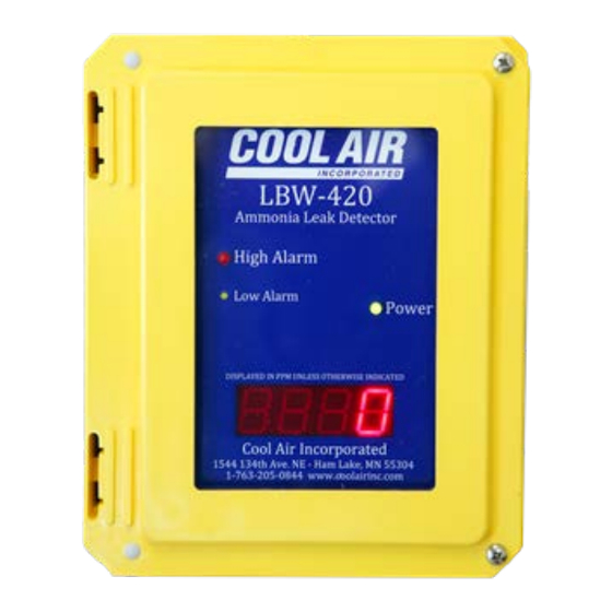
“F In” (installed) and an external temperature sensor is not installed. The Cool Air Incorporated LBW-420 Family of Detectors is a state- of-the-art ammonia leak detector that detects and displays ammonia concentrations of 0 to 1000 parts per million (PPM) (solid state sensor) or 0 to 500 parts per million (PPM) (electro-chemical sensor). -
Page 7: S T A N D A R D F E A T U R Es
The Cool Air Incorporated LBW-420-1 is a DC powered version of the LBW-420 ammonia leak detector (AC powered detector). The LBW420-1 incorporates a fully isolated DC to DC power supply, allowing the LBW-420-1 to be powered from the same DC supply as the 4-20 mA monitoring circuits without concern for ground isolation. -
Page 8: Part S D E S C R I P T I On
Ammonia concentration is displayed in parts per million and temperature is displayed in degrees Fahrenheit (“F”). The LED’s provide an indication of ammonia concentration and alarm status at a glance. Rev. 10-0 8-1-2018 Page | 6 Copyright © 2018 by Cool Air Incorporated. All rights reserved. -
Page 9: A M M O N I A S E N S O R
The front panel-mounted circuit board contains the controls necessary for programming and operating the detector. Each control is described in detail below. When the detector enclosure is Rev. 10-0 8-1-2018 Page | 7 Copyright © 2018 by Cool Air Incorporated. All rights reserved. -
Page 10: S E R V I C E S W I T C H ( S E R V I C E M O D E )
If the service jumper is not returned to off, it will automatically return to an as off state after a selected amount of time. The factory default is 15 minutes. Rev. 10-0 8-1-2018 Page | 8 Copyright © 2018 by Cool Air Incorporated. All rights reserved. -
Page 11: T H E " E N T E R " , " U P " , A N D " D O W N " P U S H B U T T O N S
(if an external temperature sensor is in use). If the switch is set to position “1”, the display will alternate between ammonia concentration and external temperature. Rev. 10-0 8-1-2018 Page | 9 Copyright © 2018 by Cool Air Incorporated. All rights reserved. - Page 12 Caution: Before closing the detector enclosure, be sure to return the rotary selector switch to position “0” or “1” to correctly display ammonia concentration, or ammonia concentration and external temperature. Rev. 10-0 8-1-2018 Page | 10 Copyright © 2018 by Cool Air Incorporated. All rights reserved.
-
Page 13: E N C L O S U R E - M O U N T E D C I R C U I T B O A R D
The enclosure-mounted circuit board is shown in the following two pictures and described in detail below. NOTE: This detector does not support a 4 to 20mA output for the temperature sensor. Rev. 10-0 8-1-2018 Page | 11 Copyright © 2018 by Cool Air Incorporated. All rights reserved. -
Page 14: P O W E R
(opposite of picture) 4-20 mA power must be supplied by an external supply. NOTE: This detector does not support a 4 to 20mA output for the temperature sensor. Rev. 10-0 8-1-2018 Page | 12 Copyright © 2018 by Cool Air Incorporated. All rights reserved. -
Page 15: J U M P E R S R E Q U I R E D
A relay is energized (a non-alarm condition) when its LED is lighted (green), and de-energized (an alarm condition) when the LED is not lighted. Rev. 10-0 8-1-2018 Page | 13 Copyright © 2018 by Cool Air Incorporated. All rights reserved. -
Page 16: E X T E R N A L C O N N E C T I O N S
PPM = 6.25 (I – 4) 0 to 100 PPM Range Where PPM equals ammonia concentration in parts per million and I equal the output current in mA. Rev. 10-0 8-1-2018 Page | 14 Copyright © 2018 by Cool Air Incorporated. All rights reserved. - Page 17 This circuit is shown in Figure 1 below: Figure 1. Rev. 10-0 8-1-2018 Page | 15 Copyright © 2018 by Cool Air Incorporated. All rights reserved.
- Page 18 LBW-420-1. The voltage drop across the detector and the receiver together must not exceed the power supply voltage. This circuit is shown in figure 2 below: Rev. 10-0 8-1-2018 Page | 16 Copyright © 2018 by Cool Air Incorporated. All rights reserved.
- Page 19 10 VDC to a maximum 30 VDC can be used. The voltage drop across the detector and the receiver together must not exceed the power supply voltage. This circuit is shown in Figure 3 below: Rev. 10-0 8-1-2018 Page | 17 Copyright © 2018 by Cool Air Incorporated. All rights reserved.
-
Page 20: I N S T A L L A T I O N A N D S E T Up
Open the detector enclosure and place the detector in service mode by moving the service jumper to the “ON” position. Rev. 10-0 8-1-2018 Page | 18 Copyright © 2018 by Cool Air Incorporated. All rights reserved. -
Page 21: P R O G R A M M I N G A N D O P E R A T I On
Set the Aux Relay pairing During normal operation, the rotary selector switch is typically set to position “0” or “1”. Set the switch to “0” to display ammonia Rev. 10-0 8-1-2018 Page | 19 Copyright © 2018 by Cool Air Incorporated. All rights reserved. -
Page 22: P R O G R A M M I N G T H E A M M O N I A P R E - A L A R M A N D A L A R M S E T P O I N T S
Press and hold the “ENTER” button for at least 2 seconds. The new set point is now programmed. Return the rotary selector switch to the desired position. Rev. 10-0 8-1-2018 Page | 20 Copyright © 2018 by Cool Air Incorporated. All rights reserved. -
Page 23: Programming The 4-20 M Arange
“OFF” position and close the detector enclosure. Programming the 4-20 mA range Rev. 10-0 8-1-2018 Page | 21 Copyright © 2018 by Cool Air Incorporated. All rights reserved. - Page 24 45d – After 45 minutes in the on position the detector will return to normal mode. 60d – After 60 minutes in the on position the detector will return to normal mode. Rev. 10-0 8-1-2018 Page | 22 Copyright © 2018 by Cool Air Incorporated. All rights reserved.
-
Page 25: A R P
Once you have selected the desired service mode timeout you must hold the ENTER button for two seconds before removing the SET 1 jumper or changing the rotary switch. Rev. 10-0 8-1-2018 Page | 23 Copyright © 2018 by Cool Air Incorporated. All rights reserved. -
Page 26: E R R O R C O D E S
Message Code Description Service jumper “on” Any error condition will cause the ammonia level 4-20 mA signal to go below zero indicating a fault. Rev. 10-0 8-1-2018 Page | 24 Copyright © 2018 by Cool Air Incorporated. All rights reserved. - Page 27 At the time of calibration, it is highly recommended to use a new test bottle of ammonia that can be purchased from Cool Air Inc. or their distributors. Rev. 10-0 8-1-2018 Page | 25 Copyright ©...
- Page 28 When the ammonia concentration reaches the Alarm, set point the Alarm LED (red) will blink. • Digital display shows an increasing concentration of ammonia in PPM. Rev. 10-0 8-1-2018 Page | 26 Copyright © 2018 by Cool Air Incorporated. All rights reserved.
- Page 29 Wait until the ammonia concentration reading is below the pre-alarm set point, then set the rotary selector switch to the desired position (typically “0” or “1”). Rev. 10-0 8-1-2018 Page | 27 Copyright © 2018 by Cool Air Incorporated. All rights reserved.
- Page 30 Remember, this step is only required if the service jumper was moved to the “ON” position in step # 2 above. Calibration is now complete. For technical support, contact Cool Air Incorporated using any of these methods: Contact:...
- Page 31 3-months bump testing in non-critical areas, and annual or twelve (12) month calibration service, which shall include proof of recordkeeping for testing and calibration by the Purchaser. Rev. 10-0 8-1-2018 Page | 29 Copyright © 2018 by Cool Air Incorporated. All rights reserved.
- Page 32 OTHER WARRANTIES, EXPRESS OR IMPLIED, INCLUDING, BUT NOT LIMITED TO, THE IMPLIED WARRANTIES OF MERCHANTABILITY OR FITNESS FOR A PARTICULAR PURPOSE ARE HEREBY DISCLAIMED Rev. 10-0 8-1-2018 Page | 30 Copyright © 2018 by Cool Air Incorporated. All rights reserved.
- Page 33 REGARDLESS OF FORM, ARISING OUT OF THE TRANSACTIONS UNDER THIS WARRANTY MAY BE BROUGHT BY THE PURCHASER MORE THAN FIVE YEARS AFTER CAUSE OF ACTIONS HAS OCCURRED. Rev. 10-0 8-1-2018 Page | 31 Copyright © 2018 by Cool Air Incorporated. All rights reserved.
- Page 34 This page intentionally left blank Rev. 10-0 8-1-2018 Page | 32 Copyright © 2018 by Cool Air Incorporated. All rights reserved.
Need help?
Do you have a question about the LBW-420-1-SS and is the answer not in the manual?
Questions and answers