Table of Contents
Advertisement
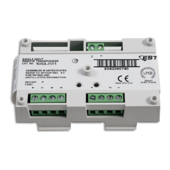
SIGA-CC1 Single Input Signal Module
Installation Sheet
Description
The SIGA-CC1 Single Input Signal Module is an addressable
module that is used to connect the following circuits:
•
Audible and visible notification appliance circuits
(synchronized or unsynchronized)
•
Speaker circuits
•
Two-way telephone communication circuits (three-state or
four-state)
Upon command from the loop controller, the module connects
supervised Class B signal or telephone circuits to the
respective riser input. The riser input can be 24 VDC (to
operate polarized audible and visible signal notification
appliances), 25 or 70 VRMS (to operate audio evacuation
speakers), or firefighter telephones.
The module does not provide signal synchronization. To meet
UL 864 requirements for horn and strobe signal
synchronization, you must install a Genesis Signal Master
module.
The SIGA-CC1 module requires one address on the signaling
line circuit (SLC). Addresses are assigned electronically. There
are no address switches.
Diagnostic LEDs provide visible indication of the state of the
module through the cover plate:
•
Normal: Green LED flashes
•
Alarm/active: Red LED flashes
© 2015 UTC Fire & Security Americas Corporation, Inc.
Personality codes
Use the personality codes described below to configure the
SIGA-CC1 module. See Table 1 for listing information
Table 1: Personality code listing information
Code
Description
5
Signal - supervised
output (Class B)
6
Telephone - three-state
(Class B)
26
Telephone - four-state
(Class B)
Personality code 5:
Signal - supervised output (Class B).
Configures the SIGA-CC1 module as a riser selector for
audible and visible notification appliance circuits or for
single-channel audio circuits. The output circuit is monitored for
open or shorted wiring. If a short exists, the module will not
activate in order to prevent shorting the riser. The module will
activate once the short is cleared.
Personality code
6: Telephone - three-state (Class B).
Configures the module as a riser selector for a three-state
firefighter telephone. When a telephone handset is plugged
into its jack or lifted from its hook, the module generates its
own ring-tone signal, making a separate ring-tone riser
unnecessary. The module sends this signal to the control panel
to indicate the presence of an off-hook condition, and waits for
the system operator to respond to the call. When the system
operator responds, the ring-tone signal is disabled.
Personality code 26:
Configures the module as a riser selector for a four-state
firefighter telephone. Operation is the same as Personality
code 6 except that the module can distinguish when a
telephone is off-hook and when the circuit is shorted, which
causes a trouble condition.
Installation
Install this device in accordance with applicable national and
local codes, ordinances, and regulations.
Notes
•
The module is shipped from the factory as an assembled
unit; it contains no user-serviceable parts and should not
be disassembled.
1 / 6
UL 864
CAN/ULC-
S527
Telephone - four-state (Class B).
P/N 387022P-EN • REV 12 • ISS 22JUN15
EN 54-18
Advertisement
Table of Contents

Summary of Contents for UTC Fire and Security EST SIGA-CC1
- Page 1 SIGA-CC1 Single Input Signal Module Installation Sheet Personality codes Use the personality codes described below to configure the SIGA-CC1 module. See Table 1 for listing information Table 1: Personality code listing information Code Description UL 864 CAN/ULC- EN 54-18 S527 ...
- Page 2 • This module does not operate without electrical power. As Figure 2: Bell circuit showing bipolar transient protector placement fires frequently cause power interruption, discuss further safeguards with the local fire protection specialist. To install the module: Write the address assigned to the module on the label provided, and then apply the label to the module.
- Page 3 Figure 3: Wiring diagram for NAC (personality code 5) (1)(2)(3)(4) (10) (3)(8) (1) Signal polarity is shown when the circuit is in supervisory state. (4) If using a G1-P Genesis series horn while connected to a Polarity reverses when the circuit is active. compatible fire alarm control panel, a CDR-3 Bell Coder must (2) Supervised.
- Page 4 Figure 4: Wiring diagram for audio (personality code 5) (1)(2)(3)(4) (10) (1) Signal polarity shown when the circuit is in supervisory state. (4) Unshielded twisted pair. (5) 47 kΩ EOLR (P/N EOL-47). Polarity reverses when the circuit is active. (2) Supervised. (6) Signaling line circuit (SLC) to next device.
- Page 5 Figure 5: Class B telephone (personality codes 6 and 26) (1) Telephone circuit. The plus and minus symbols indicate Three-state telephone circuit (personality code 6) signal polarity. (2) Supervised. (3) Power-limited unless connected to a nonpower-limited source. If the source is nonpower-limited, eliminate the power-limited mark and maintain a minimum of 0.25 in.
- Page 6 Specifications Regulatory information Operating voltage range 15.20 to 19.95 VDC Manufacturer Edwards, A Division of UTC Fire & Security Americas Corporation, Inc. Current 8985 Town Center Parkway, Bradenton, FL Standby 310 µA 34202, USA Activated 135 µA Authorized EU manufacturing representative: Maximum line impedance Refer to the control panel installation UTC Fire &...
Need help?
Do you have a question about the EST SIGA-CC1 and is the answer not in the manual?
Questions and answers