Advertisement
Quick Links
Installation Instructions
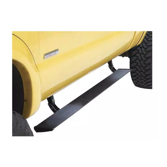
PowerBoard
Automatic Retracting Running Board
www.Bestop.com
- We're here to help! Visit our web site and click on
INSTALLATION TIME
4 Hours
TOOLS
5 mm
®
SKILL LEVEL
4 - Diffi cult
13mm
8mm, 10mm
& 13mm
Vehicle Application
• Ford F150 Super Crew Cab
2009 – Current
Part Number: 75141-15
"Ask a
Question". Click here for more
Truck Accessories by Bestop.
Advertisement

Related Manuals for Bestop PowerBoard


Summary of Contents for Bestop PowerBoard
- Page 1 Part Number: 75141-15 Automatic Retracting Running Board www.Bestop.com - We’re here to help! Visit our web site and click on “Ask a Question”. Click here for more Truck Accessories by Bestop. INSTALLATION TIME SKILL LEVEL 4 Hours 4 - Diffi cult TOOLS...
- Page 2 ® PowerBoard – Installation Instructions Parts List and Hardware Identifi cation Left End Cap, Running Board Assembly, Qty - 2 Part Number 79" - Part Number 460.87 460.83, Qty - 1 T-Nut Insert, Part 72" - Part Number 473.14 Number 460.84, M6 Nut Plate, M8-1.25 x 30 Hex Bolt,...
- Page 3 ® PowerBoard – Installation Instructions Tighten Bolts to Install Linkages Install Mounting Clips - Driver’s Side 16 ft./lbs. (22Nm) Counting from the front, locate the fi rst (1st) and last set of mounting holes on the Motor Mount the Motor Linkage to the rear and Linkage inner sill.
-
Page 4: Power Board
PowerBoard ® – Installation Instructions Remove Kick Plate and Door Install Grommet – Route Wiring Harness Sill – Passenger Side Passenger Side Route the long leg of the Wiring Harness across the Remove the Remove the tape covering the 3/4" hole in the fl oor above the Idler Linkage. - Page 5 Install Motor Reinstall the fuse in the harness. Slide Motor assembly onto drive shaft and mounting Open the doors to make sure that the PowerBoard ® bosses of Motor Linkage assembly. Use three (3) drops into position on each side of the vehicle.
- Page 6 ® PowerBoard – Installation Instructions Reinstall Step Plates Install PSA Bumper – Optional Once you have checked that the Steps function Due to variations in vehicle build, the PowerBoards ® properly, reinstall the Step Plates. Bumper may contact the vehicle body when in the up position.
-
Page 7: Limited Warranty
Damage to our products caused by accidents, fi re, consistently keep the same wire colors in their wire vandalism, negligence, misinstallation, misuse, Acts ® harnesses. The PowerBoard trigger wires need to be of God, or by defective parts not manufactured by us, Pivot...
Need help?
Do you have a question about the PowerBoard and is the answer not in the manual?
Questions and answers