Table of Contents
Advertisement
Advertisement
Table of Contents

Related Manuals for Ammann ASC 130


Summary of Contents for Ammann ASC 130
- Page 1 Operating manual ASC 130 Cummins Tier II © 5 / 2006...
- Page 2 We preserve the right for changes at pictures and data for improving the manual’s quality. Overprint and copying of any kind and also individual paragraphs is conditioned by our written approval only. ASC 130...
- Page 3 AMMANN experience in the field of road roller engineering. In order to avoid faults due to improper operation and maintenance we request that you read this operating manual with great care and keep it for later reference.
- Page 4 ASC 130...
- Page 5 / Prohlášení o shodě pečlivě uschovejte. Nové Město nad Metují, 02.05.2006. …………………………….. Quality Control Manager Ammann Czech Republic a.s. Náchodská 145 549 01 Nové Město nad Metují Czech Republic phone: +420 491 476 111, fax: +420 491 470 215 E-mail:.
- Page 6 ASC 130...
- Page 7 ! NOTICE ! As used in this operating manual, the terms „right“, „left“, „front“ and „rear“ indicate the sides of the machine moving forward. ASC 130...
-
Page 8: Table Of Contents
1.3.13. Cooling System of Hydraulic Oil ........................25 1.3.14. Fluids .................................. 26 1.3.15. Electrical Installation ............................27 1.3.16. Safety Devices ..............................27 1.3.17. Hygienical Data ..............................28 1.3.18. Requirements of Traffic Regulations ......................... 28 1.3.19. Accessories ................................ 29 ASC 130... - Page 9 2.9.3.2. Operating the machine at higher temperature and humidity ................. 115 2.9.3.3. Operating the machine in higher altitude ....................... 116 2.9.3.4. Operating the machine in extremely dusty conditions ................... 116 2.9.4. Filling tyres with water ............................. 117 2.9.5. Installing air conditioner ..........................119 ASC 130...
- Page 10 3.6.19. Checking oil in gearboxes ..........................155 Every 500 Hours or Once in 6 Month ................. 156 3.6.20. Engine fuel filter exchange ..........................156 3.6.21. Checking cooling liquid ........................... 157 3.6.22. Checking tightening bolts of wheel ......................... 158 ASC 130...
- Page 11 3.6.39. Checking and tightening bolted joints ......................181 3.7. Defects........................... 185 3.8. Appendixes..........................186 Wiring scheme ................................186 Hydraulic circuit – ASC110/130/150 – INTER - Wheel differential lock ..............190 Hydraulic circuit – ASC110/130/150 - Interaxle differential lock ATC ................ 192 ASC 130...
- Page 12 ASC 130...
-
Page 13: Specification Manual
1. SPECIFICATION MANUAL ASC 130 ASC 130... -
Page 14: Basic Data
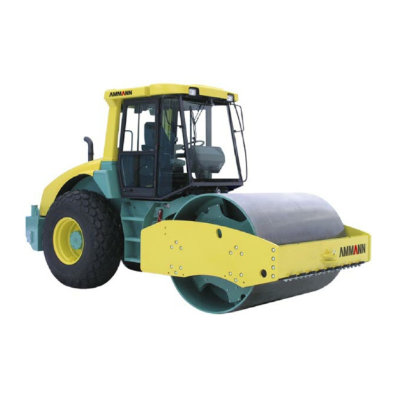
Application Range Pin label - CE The vibratory rollers of ASC 130 is especially suitable for use at mid- and large compaction jobs of highway con- struction (construction of highways, railways, airports), hydraulic construction (earth dams) and civil engineering (industrial areas, ports etc.). - Page 15 ..................ICV/PIN (Serial number of the machine) ..................Production year ..................Type of engine ..................Serial number of the engine ..................- Decal - Frame number Serial number of the CUMMINS engine Serial number of the CUMMINS engine ASC 130...
-
Page 16: Dimension Chart
1.2. Dimension Chart Dimension Chart of the Machine ASC 130 (with cab and ROPS frame) 31 0 9 ( 9 , 9 ( 5 , 1 ( 2 ) 4 ) - ( ) - ( ) - ( 31 0... - Page 17 SPECIFICATION MANUAL Dimension Chart of the Machine ASC 130 (with cab and ROPS frame) ) - ( ) - ( ) - ( ) - ( ASC 130...
- Page 18 1.2. Dimension Chart Dimension Chart of the Machine ASC 130 (without cab, with ROPS frame) 31 0 9 ( 9 , 9 ( 5 , 1 ( 2 ) 4 ) - ( ) - ( ) - ( 31 0...
- Page 19 SPECIFICATION MANUAL Dimension Chart of the Machine ASC 130 (without cab, with ROPS frame) ) - ( ) - ( ) - ( ) - ( ASC 130...
-
Page 20: Technical Data
1.3. Technical Data 1.3.1. Weights ASC 130 D ASC 130 PD Operation weight with cab EN500-1 kg (lb) 12400 (27337) 12500 (27558) Operation weight EN500-1 to drum kg (lb) 8100 (17857) 8200 (18078)) to axle kg (lb) 4300 (9480) 4300 (9480) - Page 21 SPECIFICATION MANUAL ASC 130 HD ASC 130 HDPD ASC 130 HT ASC 130 HTPD Operation weight with cab EN500-1 kg (lb) 13635 (30059) 13735 (30280) Operation weight EN500-1 to drum kg (lb) 8135 (17934) 8235 (18155) to axle kg (lb)
-
Page 22: Travel Parameters
1.3. Technical Data 1.3.2. Travel Parameters ASC 130 D ASC 130 PD Travel speed infinitely adjustable in both directions 1st speed range (work) km/h 0 - 2,5 0 - 2,5 (MPH) (0 - 1,55) (0 - 1,55) 0 - 3,5... - Page 23 SPECIFICATION MANUAL ASC 130 HT ASC 130 HTPD Travel speed infinitely adjustable in both directions 1st speed range (work) km/h 0 - 2,4 0 - 2,4 (MPH) (0 - 1,49) (0 - 1,49) 0 - 3,1 0 - 3,1 (0 - 1,93)
-
Page 24: Vibration
Engine fulfills requirements of: Dir. 97/68/EU Stage 2 EPA/CARB 40 CFR Part 89 Tier 2 Exact denomination of these parts is dependent on modification of the engine. For spare parts ordering always refer to the serial number of your engine. ASC 130... -
Page 25: Axle
Hydraulic power steering with two hydraulic cylinders Hydraulic pump of steering JIHOSTROJ Q 27 R Power steering unit Mannesmann Rexroth Servostat 8477955593 Safety pressure MPa (PSI) 15 (2175) Hydraulic cylinders 2x HV 90/45/400 Steering angle (±) 36° Oscillation angle (±) 10° ASC 130... -
Page 26: Vibratory Drum
1.3. Technical Data 1.3.8. Vibratory Drum ASC 130 D ASC 130 PD Drum dia mm (in) 1500 (59,0) 1440 (56,7) Drum dia over pads mm (in) 1640 (64,6) Drum width mm (in) 2200 (86,6) 2200 (86,6) Drum shell thickness mm (in) -
Page 27: Hydrostatic Drive Of Vibration
Hand pump Technometra RC 16 Hydraulic locks - for hood lifting and lowering 2x Hytos RJV1-05 Typ 535-0118 - for cab lifting and lowering Hytos RJV1-05 Typ 535-0118 1.3.13. Cooling System of Hydraulic Oil Oil cooler Emmegi 34299 ASC 130... -
Page 28: Fluids
Liquid-filled tyres up to - 25 °C (-13 °F) kg (lb) 2 x 600 (2 x 1323) to 0 °C ( 32 °F) kg (lb) 2 x 500 (2 x 1102) They represent additional weight for HD, HT ASC 130... -
Page 29: Electrical Installation
Hydraulic locks protective device preventing fall of the hood or cabin at failure of the lifting system Oil leak protection automatically stops the machine and optically signals in a case of oil leak Battery disconnector disconnects electrical installation ASC 130... -
Page 30: Hygienical Data
= 91 dB(A) 1.3.18. Requirements of Traffic Regulations The basic machine model is not intended to be moved under own power on public roads, since its appointment is not in compliance with the regulation for public roads. ASC 130... -
Page 31: Accessories
2 bolts M 20 x 110 (8G) 5 bolts M 20 x 140 (8G) 5 bolts M 20 x 160 (8G) Tightening torque Nm (in lb) 314 (2776) Distributor HP8-1-STA Safety pressure MPa (PSI) 20 (2900) Hydraulic cylinders 2x HM 63/32/500 111131 ASC 130... - Page 32 II. It is mounted on the ROPS protective frame, and protects the driver from falling objects, such as trees, boulders, etc., Cover weight kg (lb) 140 (309) Attached to ROPS by 4 bolts M16x30(8G) Tightening torque Nm (in lb) 165 (1457) Details are listed on label on the cover. ASC 130...
- Page 33 Sauer MCX 106A 1005X 742361 F) FOPS cab This is a standard cab with a reinforced roof protecting against falling objects. The cab complies with international standards ISO 3449:1992; SAE J 231:JAN81; AS 2294:1990 and approval level II. ASC 130...
- Page 34 ASC 130...
- Page 35 SPECIFICATION MANUAL ASC 130...
- Page 36 ASC 130...
- Page 37 SPECIFICATION MANUAL ASC 130...
- Page 38 ASC 130...
- Page 39 SPECIFICATION MANUAL ASC 130...
- Page 40 ASC 130...
-
Page 41: Operating Instructions
2. OPERATING INSTRUCTIONS ASC 110, ASC 130, ASC 150 ASC 200 and ASC 250 (Cummins tier 2) ASC110/ASC130/ASC150/ASC200/ASC250... - Page 42 ASC110/ASC130/ASC150/ASC200/ASC250...
-
Page 43: Safety Regulations
2.1. Safety Regulations OPERATING INSTRUCTIONS 2.1.1. Safety Regulations and Instruction for 2.1.1.2. Operation in an imperiled area Operation of the Machine Whatever damage to service networks must be reported immediately to the operating company, simultaneously, The safety regulations stated in the individual chapters of access by unauthorized persons to the imperiled area the documentation delivered with the machine are to be must be limited. -
Page 44: Work Safety Precepts On Behalf Of The Operator
2.1. Safety Regulations 2.1.1.3. Work safety precepts on behalf of the When using ROPS frame operator • the machine frame in the spot of connection must not be damaged (broken bent, etc.) The operator • • must make sure that the machine is operated only the ROPS frame itself must not be corroded, damaged, under conditions and for the purpose to which the or show any hair fractures or breaks,... -
Page 45: Requirements For The Competence Of The Driver
OPERATING INSTRUCTIONS 2.1.2. Requirements for the competence of 2.1.3. The driver’s duties the driver • Before the start of operations, the driver must become • acquainted with instructions published in the machine The roller may be operated by a driver, who has been documentation, particularly with safety rules, and trained to ISO 7130 and other local and national adhere to them. - Page 46 2.1. Safety Regulations • To follow safety messages under all Following the warning signal the operator may start circumstances to avoid risk of the machine first after all personnel have left the serious injury or death. vicinity of the machine. On a difficult to oversee site the machine may be started after a certain time allowed for vacating it.
-
Page 47: Forbidden Actions
OPERATING INSTRUCTIONS • 2.1.4. Forbidden actions leave the machine unsecured, unless secured against misuse It is not permitted to • eliminate safety and protection devices, fusing, or change their settings, • operate the machine under the influence of alcohol or •... -
Page 48: Safety Signs And Symbols Marked On The Machine
2.1. Safety Regulations 2.1.5. Safety signs and symbols marked on the machine ASC110/ASC130/ASC150/ASC200/ASC250... - Page 49 OPERATING INSTRUCTIONS Risk of grasp Dangerous space with risk of grasp. (Symbols located on the left and right side of the rear crossbar of the front frame) Risk of burn Risk of burn. Do not touch the hot parts of the machine until you’ve checked they are cold enough.
- Page 50 2.1. Safety Regulations Safety belt Fasten your safety belt before machine start. (Symbol located on the left side of the control board) Machine maximum height Attention to be paid when driving through places with a height limit. (Symbol located on the left side, on the frame under the cab) Battery disconnector Switch the battery disconnector into „O“...
- Page 51 OPERATING INSTRUCTIONS 15. Ear protection If there is no cab at the machine or if working with the windows open, be sure to wear an ear protection. (Symbol located on the central post of the control) 16. Noise emission Symbol located on the right side of frame under cabine. 17.
-
Page 52: Environmental And Hygienical Principle
2.2. Environmental and Hygienical Principle 2.2.2. Ecological rules The user must observe general rules of health and environment protection, and all applicable laws, • The fills of specific systems and some components notices and regulations in the country of use, become waste with risk factors to the environment when operating or parking the machine. -
Page 53: Conservation And Storing
2.3. Conservation and Storing OPERATING INSTRUCTIONS 2.3.1. Short-term storage of 1 to 2 months 2.3.2. Conservation and storage for more than 2 months Wash and clean the machine thoroughly. Warm up the engine to operating temperature before starting conser- Same rules for short-term storage apply here as well, vation for storage. -
Page 54: De-Conservation And Inspection Of Brand New Machines
2.3. Conservation and Storing 2.3.3. De-conservation and inspection of brand new machines Check the machine against delivery documentation. Check whether any parts were damaged during transport or are missing. Inform the shipper of any discrepancies. Before starting operations again, wash off conservation with high-pressured hot water with ordinary degreasing means added as directed, while observing environmental rules. -
Page 55: Liquidation Of The Machine After Termination Of Its Service Life
2.4. Liquidation of the Machine After Termination of Its Service Life In disposing of the machine at the end of its life, the user must observe national regulations and laws on waste disposal and protection of environment. We recommend that you refer always to •... - Page 56 ASC110/ASC130/ASC150/ASC200/ASC250...
-
Page 57: Description Of The Machine
2.5. Description of the machine OPERATING INSTRUCTIONS Main Components of the Machine 1 - Drum frame 13 - Engine 2 - Vibratory drum 14 - Hydraulic oil cooler 3 - Scraper 15 - Liquid radiator 4 - Articulated joint 17 - Driver’s workplace 5 - Tractor frame 18 - Pump of travel 6 - Axle... -
Page 58: Controls And Control Devices
2.6. Controls and control devices Controls and control devices ASC110/ASC130/ASC150/ASC200/ASC250... - Page 59 OPERATING INSTRUCTIONS 1 - Travel control 2 - Transport gear selector 3 - Working gear pre-selector 4 - Parking brake switch 5 - Emergency brake push-button 6 - Vibration switch 7 - Steering wheel 8 - Engine speed selector 9 - Switchbox 10 - Hydraulic oil thermometer 11 - Fuel gauge 12 - Revolution counter...
- Page 60 2.6. Controls and control devices Layout of controls and cabin accessories 44 - Windshield washer switch 45 - Fan switch 46 - Rear wiper switch 47 - Front wiper switch 48 - Cabin illumination 49 - Vent jets 50 - Sun shield 51 - Glove box 52 - Rear mirrors ASC110/ASC130/ASC150/ASC200/ASC250...
- Page 61 OPERATING INSTRUCTIONS Cabin 53 - Battery disconnector 64 - Fire extinguisher 54 - Cabin lifting and lowering switch 65 - Washer tank 55 - Bonnet lifting and lowering switch 66 - Bottle holder 56 - Manual hydro-generator for lifting and lowering of 67 - Storage compartment driver’s stand and bonnet 68 - Cabin ventilation filter...
- Page 62 2.6. Controls and control devices Travel control (1) Use this control to adjust the travel direction ! NOTE ! and speed. The travel speed depends on degree of the control movement from the ne- The engine can only be started when in neutral. utral position.
- Page 63 OPERATING INSTRUCTIONS Parking brake push-button (4) Transport gear selector (2) Use the brake of the machine when the engine is running. When the gear selector is on, the transport gear is enga- The brake pilot lamp is shining. Then the operator can ged (”rabbit”...
- Page 64 2.6. Controls and control devices ASC110/ASC130/ASC150/ASC200/ASC250...
- Page 65 OPERATING INSTRUCTIONS Steering wheel (7) Fuel gauge (11) Use the steering wheel to steer the machine. Indicates the level of fuel in fuel tank. ! NOTE ! When driving without vibration, set optimum speed ! NOTE ! (1800 rpm) to ensure safe steering Check the gauge regularly during operation.
- Page 66 2.6. Controls and control devices ASC110/ASC130/ASC150/ASC200/ASC250...
- Page 67 OPERATING INSTRUCTIONS Engine idling switch (15) Troubleshooting switch (17) Use the switch to turn on engine idling with an engine start. The switch is in the middle position. Signal lamp in the switch will light up upon activating. Turn it continuously any direction (+ forward or - backward) to find defects according to flashing codes of signal lamps (18) or (19).
- Page 68 2.6. Controls and control devices ASC110/ASC130/ASC150/ASC200/ASC250...
- Page 69 OPERATING INSTRUCTIONS Battery charging - signal lamp (22) Stop engine - signal lamp (18) Indicates proper function of battery charging. The lamp Stop the engine as soon as possible if this red lamp goes must go on at turning the ignition key (7) to ”I” position and go off after the engine has been started.
- Page 70 2.6. Controls and control devices ASC110/ASC130/ASC150/ASC200/ASC250...
- Page 71 OPERATING INSTRUCTIONS Clogged air cleaner - signal lamp (25) Vibration on - signal lamp (28) This lamp (on) indicates excessively clogged air filter. This lamp (on) indicates vibration is on. ! NOTE ! Clogging of the pressure filter of hydraulic oil - signal lamp (29) Replace filters immediately! At oil temperature of 50 - 60°C, this lamp (on) indicates...
- Page 72 2.6. Controls and control devices ASC110/ASC130/ASC150/ASC200/ASC250...
- Page 73 OPERATING INSTRUCTIONS Warning lights switch (35) Horn push-button (31) Use the switch to turn on warning lights. Press the button to horn. The flashing lamp in the switch indicates lights on. Rear lights switch (32) Beacon switch (36) Use the switch to turn on rear lights. The lamp in the switch indicates lights lit up.
- Page 74 2.6. Controls and control devices Drum traction slip control switch (38) Heating fan switch (39) Located on the control panel if the machine is not equip- position - off ped with ASC - Anti Slip Control function. position - high speed of fan motor The lamp in the switch indicates the function on.
- Page 75 OPERATING INSTRUCTIONS ASC connector (41) Use this connector to connect a service device (notebook) Windshield washer switch (44) in order to communicate with the control module (susmic) and to troubleshoot. Use the switch to turn on front and rear washers at the same time.
- Page 76 2.6. Controls and control devices Roof light (48) Glove box (51) Use this box to store first aid kit. Vent jets (49) Tilt the vents to adjust amount of fresh air, swivel to adjust Rear mirrors (52) direction. When working in congested environment or when trans- porting the machine, rear mirrors can be folded 90 degre- es from A working position to B transporting position.
- Page 77 OPERATING INSTRUCTIONS Lifting and lowering driver’s stand switch Battery disconnector (53) (54), Use the disconnector (1) to disconnect battery. O position - electric system of the machine is disconnected I position - electric system of the machine is connected Lifting and lowering bonnet switch (55) Press buttons (54) or (55) to turn on lifting or lowering.
- Page 78 2.6. Controls and control devices Fuse (57) Driver’s seat (58) Secures protection of electric pump used for lifting and Adjustable, sprung, equipped with two-point retractor belt lowering of bonnet and driver’s stand. (1). Driver must fasten the seatbelt ! NOTE ! during drive! Replace the fuse with a genuine one of the same rate 50 A.
- Page 79 OPERATING INSTRUCTIONS SEAT ADJUSTING ELEMENTS: Horizontal seat squab adjustment - raise the lever to move the seat single handedly forward or backward. Backrest inclination adjustment - raise the lever to tilt the backrest infinitely as necessary. Horizontal seat adjustment - raise the handle to move the seat with control panel forward or backward.
- Page 80 2.6. Controls and control devices Vertical seat adjustment - grasp the seat at the bottom Arm rest adjustment - raise and turn the screw to cast and lift it to gradually adjust height of the seat. The seat down a raise the rest. must click into the position.
- Page 81 OPERATING INSTRUCTIONS Box (59) Heating control (61) Fold out the back wall of the seat to use the box to store Amount of liquid flowing to the heating radiator can be operation manual. infinitely controlled from fully closed (valve closed) to fully open valve.
- Page 82 2.6. Controls and control devices Heating vents (62) Front and rear windshields are blown with hot air to avoid Tilt the vents to adjust amount of fresh air, swivel to adjust dewing. direction. ! NOTE ! Ensure proper ventilation while heating! ASC110/ASC130/ASC150/ASC200/ASC250...
- Page 83 OPERATING INSTRUCTIONS Hydro-generator control lever (63) Fire extinguisher (64) Use the lever to control manual hydro-generator of lifting For instructions how to use the fire extinguisher, see the and lowering the cabin and bonnet. label. Get familiar with using the fire extinguisher! Inspect the fire extinguisher regular- ASC110/ASC130/ASC150/ASC200/ASC250...
- Page 84 2.6. Controls and control devices Washer tank (65) Bottle holder (66) The tank is used for supplying solution to two pumps of Fold out the holder to keep standard bottle. windshield washers - for front and rear washer jets. ! NOTE ! Fill the tank with anti-freeze solution before winter! ASC110/ASC130/ASC150/ASC200/ASC250...
- Page 85 OPERATING INSTRUCTIONS Storage compartment (67) Engine fuses (74) Compartment for driver’s personal belongings. Fuses F10 – F12 –7.5 A ... power supply engine electro- nics Fuses F13 – F14 -10 A ..power supply injection pump Fuse F15 - reserve Connector (70) Use this connector for warning beacon.
-
Page 86: Controlling And Operation Of The Machine
2.7. Controlling and operation of the machine 2.7.1. Starting the engine WARNING! Do not start longer than 30 seconds. Wait for 2 Start the engine only from the driver’s minutes before next starting. seat! Repeat starting procedure 3 times at most; then Blow horn before starting the engine detect the cause in fuel system. - Page 87 OPERATING INSTRUCTIONS ASC110/ASC130/ASC150/ASC200/ASC250...
- Page 88 2.7. Controlling and operation of the machine • After starting up, disconnect starting cables in reverse ! NOTE ! order. Starting voltage of the external starting source • If using a starting power unit without connected batte- must be 24 V. ries, do not disconnect the power unit before a battery Keep the specified order of operations under all will be connected in the machine.
-
Page 89: Travel And Reversing Without Vibrations
OPERATING INSTRUCTIONS • 2.7.2. Travel and reversing without Turn off gear selector (2) to set the working gear mode. • vibrations Select appropriate range of working gear on the wor- king gear pre-selector (3). • Turn off the IDLE switch (15). Use selector (8) to adjust Give the acoustic signal before appropriate engine speed - approx. - Page 90 2.7. Controlling and operation of the machine Selecting driving direction and speed Do not drive across (traverse) slopes • with high inclination! Drive directly Move the travel control (1) from neutral to the required up the slope! direction - little movement = low speed and vice versa. Upon moving the travel control (1), the neutral (24) signal lamp will go off.
-
Page 91: Travel With Vibration
OPERATING INSTRUCTIONS 2.7.3. Travel with vibration • • Turn off gear selector (2) to set the working gear mode. Start moving and use switch (6) to turn on vibration. Signal lamp (28) will light up; the drum will start • Switch pre-selector (3) to appropriate working gear vibrating. -
Page 92: Stopping The Machine And Engine
2.7. Controlling and operation of the machine 2.7.4. Stopping the machine and engine • Use switch (6) to deactivate vibration - signal lamp (28) ! NOTE ! will go off. • Do not stop the engine immediately; let it idle for 3 Use control (1) to stop the machine - signal lamps (23) minutes to cool it down and turbocharger. -
Page 93: Emergency Stopping
OPERATING INSTRUCTIONS 2.7.5. Emergency stopping ! NOTE ! Use this way of stopping in case of defect, when the machine cannot be Before restarting the engine, turn the button (5) in stopped by moving travel control (1) the direction of the arrow, move the travel lever (1) to neutral position, or is it impossible in to ”N”... -
Page 94: Dead Parking Of The Machine
2.7. Controlling and operation of the machine 2.7.6. Dead parking of the machine • Stop the machine - see chapter 2.7.4. Stop the machine on even and firm • Turn off the battery disconnector. surface. • Clean the machine from dirt (scraper and tyres). Check the place of parking for risk of •... -
Page 95: Troubleshooting According To Flashing Codes
OPERATING INSTRUCTIONS 2.7.7. Troubleshooting according to flashing NOTE If only one defect is identified, its error code will be codes signalled repeatedly even if you press switch (17) in either direction. • In case of engine fault, either stop engine red signal lamp (18) or engine warning yellow lamp (19) will light up. -
Page 96: Atc Function
In case of ATC defect, transport gear cannot be engaged or, if adhesion limit is exceeded, drum or one of wheels will • ATC - Ammann Traction Control - prevents slipping of start slipping. wheels and drum in case of exceeding adhesion limit when driving in heavy conditions or on slopes. -
Page 97: Blade
OPERATING INSTRUCTIONS 2.7.9. Blade • Unlock the blade on both sides. • • For unlocked blade. For locked (secured) blade. ASC110/ASC130/ASC150/ASC200/ASC250... - Page 98 2.7. Controlling and operation of the machine • Start the engine. Switch off the ”Idle” switch (15), set maximum RPM (8) (or those proportional to the subse- quent output). Switch off the gear selector (2) and choose a suitable range of speed of operation on the appropriate preselector (3).
- Page 99 OPERATING INSTRUCTIONS • • Lower the blade down to the earth by shifting the blade Return the controller (pedal) to ”0” position and start controller forwards from ”0” position to ”III” (floating driving. position). • The blade then starts digging after shifting the control- or pedal.
- Page 100 2.7. Controlling and operation of the machine • • Floating position can be used for shovelling the mate- After finishing work with the blade secure it in the upper rial. The blade slides over removable skids (96). It can position using both safety pull rods (1) and pins (2). be also used for the regressive spreading and evening of the material.
-
Page 101: Lifting Driver's Stand And Bonnet
OPERATING INSTRUCTIONS • 2.7.10. Lifting driver’s stand and bonnet Move the lever to A position (lifting). ! NOTE ! Fold the seat and rest before lifting drivers stand. Just the machine with integrated roof in ROPS. • Insert the lever to the pump and lift the driver’s stand. Lifting driver’s stand •... - Page 102 2.7. Controlling and operation of the machine Lifting bonnet Lifting and lowering using electric-hydraulic pump (op- • tional) Move the lever to A position - (lifting). • Remove nuts of the driver’s stand. • Insert the lever to the pump and lift the driver’s stand. •...
- Page 103 OPERATING INSTRUCTIONS Manual lifting and lowering Driver’s stand • • In case of el-hydraulic unit or flat battery, use the Remove nuts of the driver’s stand. manual hydro-generator to perform lifting and lowe- ring. • Open the cover (1) on the left side under the driver’s stand.
- Page 104 2.7. Controlling and operation of the machine • Bonnet Unlock the safety pin of lifting before starting lowering. • Push the sliding valve (3) on the other side of the • Push the sliding valve (3) on the switchboard (2) and switchboard (1), secure it with safety pin (4) and pump secure it in the position with safety pin (4).
-
Page 105: Shifting The Machine (Transport)
2.8. Shifting the machine (transport) OPERATING INSTRUCTIONS 2.8.1. Transporting the machine on its own During driving up and down the transporting vehicle, all persons but The machine may drive on its own between worksites if not the driver must be away from the using public roads. -
Page 106: Transporting The Machine By Rail
2.8. Shifting the machine (transport) 2.8.3. Transporting the machine by rail Bulgarian Railways Greek Railways • The height with cabin and safety frame - 3150 mm (124 National Company of Luxembourg Railways in) - conforms to some load dimensions of European Rumanian Railways railroad freight traffic. -
Page 107: Loading The Machine
Use drive-up ramps or crane to load the machine to a transporting vehicle. • The roller is equipped with lifting eyes for loading by crane: ASC 110 ASC 130* • Fold arm (2) and secure it with pin (1) and locking pin. ASC 150* ASC 200 ASC 250* •... - Page 108 2.8. Shifting the machine (transport) • Unlock and pull pins (1) of two blocks (2) on both sides from the joint. (options) Do not step under the hanging load! Return the safety arm and blocks to default positions after loading is complete.
-
Page 109: Dismantling Cabin And Rops Frame
OPERATING INSTRUCTIONS 2.8.5. Dismantling cabin and ROPS frame • If the machine height on the transporting vehicle is higher than allowed for transport, dismantle cabin and ROPS frame. Dismantling ROPS • Hang the frame by lifting eyes. • Disconnect electric system by disconnecting connec- tor between steering column and front windshield. -
Page 110: Using The Machine Under Special Conditions
2.9. Using the machine under special conditions 2.9.1. Towing Options: • Pin is also used for front towing lug on the crossbar of • In case of failure the Machine can be towed to a the front frame. distance necessarily needed. For this reason the Machine has been fitted with two eyes on the frame of drum. - Page 111 OPERATING INSTRUCTIONS • Releasing drum and wheels for ASC 110÷150: Connect hose 1 of the manual hydro-generator with hose 3 of pressure filter. • Release all multi-plate brakes to avoid slipping of drum and wheels. • Release hose 1 in clip 2. •...
- Page 112 2.9. Using the machine under special conditions • Releasing brakes of the drum and the wheels for ASC Unscrew central parts (1) (haxagonal 27 mm (11/16”)) 200÷250 by three turns anti-clockwise on two multi-purpose safety valves of the hydro-generator of travel. •...
- Page 113 OPERATING INSTRUCTIONS • To put the machine into the original condition for ASC Turn the ignition key to I position and check signal 110÷150: lamp of brake (23) switched off. • Disconnect hose (1) from hose (3) in the quick coupling (2).
- Page 114 2.9. Using the machine under special conditions • To put the machine into the original condition for ASC Screw back multi-purpose valves on the hydro- 200÷250 generator. • Disconnect hoses (4). • Put the manual hydro-generator lever (63) to the hol- der under the driver’s stand.
-
Page 115: Driving With Vibrations On Compacted And Hard Material
OPERATING INSTRUCTIONS 2.9.2. Driving with vibrations on compacted After releasing brakes and short- and hard material circuiting the travel hydraulic circuit, all brakes are out of operation! When driving with vibration on more compacted subgrade Use unimpaired towing cables or material, so called vibro-strike may occur. -
Page 116: Using The Machine Under Heavy Weather Conditions
2.9. Using the machine under special conditions 2.9.3. Using the machine under heavy l i o weather conditions 2.9.3.1. Operating the machine under low y t i temperature Compacting in winter depends on content of fine particles y t i and water in compacted soil. -
Page 117: Operating The Machine At Higher Temperature And Humidity
OPERATING INSTRUCTIONS 2.9.3.2. Operating the machine at higher ! NOTE ! temperature and humidity When working under extreme conditions, when Engine power output decreases with increasing tempera- cooling liquid or hydraulic oil temperatures reach ture and air humidity. With regards to the fact that the two maximum allowed limits, it is possible to increase factors are independent of each other, their influence can cooling capacity of the cooling system by removing... -
Page 118: Operating The Machine In Higher Altitude
2.9. Using the machine under special conditions 2.9.3.3. Operating the machine in higher 2.9.3.4. Operating the machine in extremely altitude dusty conditions In higher altitude, engine power output decreases as a result of lower atmospheric pressure and specific density ! NOTE ! of incoming air. -
Page 119: Filling Tyres With Water
OPERATING INSTRUCTIONS 2.9.4. Filling tyres with water This is useful to increase weight allocated to axle and to lower gravity center when working in extreme conditions. Fill the inside of tyres with a solution of water, hydrated lime (calcium hydroxide) and anhydrous calcium chloride (CaCl or magnesium chloride (MgCl ). - Page 120 2.9. Using the machine under special conditions • Draining: Screw the filler into the opening see gr. 635 Parts katalogue. • Secure the drum by scotch blocks from both sides, lift • Rotate tyres so that fillers are at bottom positions. the rear part of the roller and release brake of wheel •...
-
Page 121: Installing Air Conditioner
OPERATING INSTRUCTIONS 2.9.5. Installing air conditioner When retrofitting air condition unit, it is necessary to keep sufficient distance between the oil cooler and air conditi- oner condenser in order that air flow the machine cooling system is not affected. (This would reduce cooling capa- city of radiators.) Minimum distance is 50 mm (2 in). - Page 122 ASC110/ASC130/ASC150/ASC200/ASC250...
- Page 123 OPERATING INSTRUCTIONS ASC110/ASC130/ASC150/ASC200/ASC250...
- Page 124 ASC110/ASC130/ASC150/ASC200/ASC250...
-
Page 125: Maintenance Manual
3. MAINTENANCE MANUAL ASC 110, ASC 130 and ASC 150 (Cummins tier 2) ASC110 / ASC130 / ASC150... - Page 126 ASC110 / ASC130 / ASC150...
-
Page 127: Safety Standards At Lubrication And Maintenance
3.1. Safety Standards at Lubrication and Maintenance 3.1.1. Safety during maintenance 3.1.2. Fire safety during changing contents • Lubrication, maintenance and adjustment process: From fire safety point of view, inflammable liquids used in the machine are classified into following clas- •... -
Page 128: Environmental And Health Regulations
3.1. Safety Standards at Lubrication and Maintenance 3.1.3. Environmental and health regulations 3.1.3.2. Environmental principles During operation and maintenance of the machines the Contents of specific machine systems and user must follow general principles of health and environ- some of its parts are wastes dangerous to the ment protection, and laws, notices and regulations rela- ting to this subject, applicable in the territory. -
Page 129: Specification Of Fluids
3.2. Specification of fluids MAINTENANCE MANUAL 3.2.1. Engine oil Engine oil is specified by its performance and viscosity classifications. Performance classification according to API (AMERICAN PETROLEUM INSTITUTE) CCMC (COMMITE of COMMON MARKET AUTOMOBILE CONSTRUCTORS). ACEA (ASSOTIATION DES CONSTRUCTEURS EURO- PÉENS DE AUTOMOBILE) Viscosity classification To determine SAE (Society of Automotive Engineers) viscosity class, the ambient temperature and type of ope-... -
Page 130: Fuel
3.2. Fills specification 3.2.2. Fuel 3.2.3. Coolant Diesel is used as fuel: Use coolant consisting of 50% of frost-resistant ethyl glycol agent and water according to Table all year-round • CEN EN 590 or DIN/EN 590 (draft) for the cooling system of the engine. Use the coolant with •... -
Page 131: Hydraulic Oil
MAINTENANCE MANUAL MAINTENANCE MANUAL 3.2.4. Hydraulic oil ! NOTE ! At high ambient temperatures, when the oil tempe- For use in the hydraulic system of the machine, only high- rature reaches continual 90 °C (194 °F), we recom- quality hydraulic oils of output class according to ISO mend replacing the oil with one of kinetic viscosity 6743/HV (equal to DIN 51524 part 3 HVLP;... -
Page 132: Gearbox Oil
3.2. Fills specification 3.2.5. Gearbox oil 3.2.6. Lubricating grease Use high quality oils complying with API GL-5 or EP or MIL- Plastic grease containing lithium in compliance with NLGI- L-2105 C for lubricating the drum gearbox and axle (whe- 2 regulation (Mobilplex EP-1, Retinax A, Alvania, Grease els) drive gearboxes. -
Page 133: Fills
3.3. Fills MAINTENANCE MANUAL MAINTENANCE MANUAL s l l . . . l l i f t i t l i o c i t c i l l i o l i o l i o t n i t n i c i t n i l... -
Page 134: Lubrication And Maintenance Chart
3.4. Lubrication and Maintenance Chart ASC110 / ASC130 / ASC150... - Page 135 MAINTENANCE MANUAL ASC110 / ASC130 / ASC150...
-
Page 136: Lubrication Chart
3.5. Lubrication Chart ASC110 / ASC130 / ASC150... -
Page 137: Individual Operations Of Maintenance
3.6. Individual Operations of Maintenance MAINTENANCE MANUAL Ensure regular and repetitive lubrication and maintenance at intervals according to daily reading of the working hours counter. This manual includes only basic information on the engine; the rest is provided in the operation and maintenance manual of the engine, which is a part of documentation supplied with the machine. -
Page 138: Every 20 Hours Or Daily
3.6. Individual Operations of Maintenance Every 20 Hours or Daily Every 20 Hours or Daily • 3.6.1. Checking the amount of oil in the Refill oil after removing the filler plug (2) through the oil filler. Wait approx. 1 min until the level is stable and engine check again. -
Page 139: Checking Cooling Liquid Of The Engine
MAINTENANCE MANUAL Every 20 Hours or Daily Every 20 Hours or Daily 3.6.2. Checking cooling liquid of the engine ! NOTE ! The level must not fall below the level indicator • Place the roller onto flat, firm surface and stop the eyesight. -
Page 140: Checking Oil In The Hydraulic Tank
3.6. Individual Operations of Maintenance Every 20 Hours or Daily Every 20 Hours or Daily • 3.6.3. Checking oil in the hydraulic tank Refill oil using filling device by means of filling quick coupling according to chapter 3.6.29. • Place the roller onto flat, firm surface and stop the engine. -
Page 141: Checking The Engine Belt
MAINTENANCE MANUAL Every 20 Hours or Daily Every 20 Hours or Daily 3.6.4. Checking the engine belt 3.6.6. Checking the engine inlet piping • • Check visually the belt, search for its damage. Cracks Check the tightness of engine inlet piping. perpendicular to the belt are not defects. -
Page 142: Checking The Vacuum Valve Of The Air Cleaner
3.6. Individual Operations of Maintenance Every 20 Hours or Daily Every 20 Hours or Daily 3.6.7. Checking the vacuum valve of the air cleaner • Clean the exit slit and remove the trapped dust by NOTE pushing. • Collected dust is stored in the dust valve and automa- tically emptied during the machine operation. -
Page 143: Checking Fuel Level
MAINTENANCE MANUAL Every 20 Hours or Daily Every 20 Hours or Daily • 3.6.8. Checking fuel level Refill the fuel tank up to the lower edge of the tank filler through the strainer. • Check the amount of fuel on fuel gauge; in case of insufficient amount refill fuel. -
Page 144: Cleaning The Water Separator
3.6. Individual Operations of Maintenance Every 20 Hours or Daily Every 20 Hours or Daily • 3.6.9. Cleaning the water separator Then push the valve up and screw it in. • Prepare a vessel for draining the settling. ! NOTE ! •... -
Page 145: Checking Warning And Control Devices
MAINTENANCE MANUAL Every 20 Hours or Daily Every 20 Hours or Daily 3.6.10. Checking warning and control devices • Turn on switches (31, 32, 33, 34, 35, 36, 37), test the horn, beacon and lights. Continuously check devices and signal lights during operation Repair any indicated defects immedia- tely! -
Page 146: Every 100 Hours
3.6. Individual Operations of Maintenance Every 100 Hours Every 100 Hours 3.6.11. Checking the tyre pressure • Inflate the tyres (1) by pressured air through tyre valves (2). • Check the pressure in cold tyres, by air pressure meter. • Keep the tyre pressure at 160 kPa (23.2 PSI). -
Page 147: Every 250 Hours Or Once In 3 Months
MAINTENANCE MANUAL Every 250 Hours or Once in 3 Months Every 250 Hours or Once in 3 Months • 3.6.12. Engine oil exchange Clean the area around the oil filter head. Dismantle the filter (1). • Place the roller onto flat, firm surface. •... - Page 148 3.6. Individual Operations of Maintenance Every 250 Hours or Once in 3 Months Every 250 Hours or Once in 3 Months • Wipe the sealing with oil. • Check the drain plug sealing replace it, if damaged. • Check the engine sump thread and clean the contact area of the sealing.
-
Page 149: Checking The Injection Pump
MAINTENANCE MANUAL Every 250 Hours or Once in 3 Months Every 250 Hours or Once in 3 Months NOTE 3.6.13. Checking the injection pump • After refilling, start the engine for 2 - 3 min. Check tightness of drain plug and filter. •... -
Page 150: Checking The Cooling Circuit Of The Engine
3.6. Individual Operations of Maintenance Every 250 Hours or Once in 3 Months Every 250 Hours or Once in 3 Months 3.6.14. Checking the cooling circuit of the 3.6.15. Checking batteries engine • Place the roller onto flat, firm surface. •... - Page 151 MAINTENANCE MANUAL Every 250 Hours or Once in 3 Months Every 250 Hours or Once in 3 Months or hydrometer. Always follow the instructions of the manufacturer, when working with the battery. Use protective gloves and eye protecti- on equipment when working with the battery.
-
Page 152: Checking The Function Of Vacuum Switch Of The Air Cleaner
3.6. Individual Operations of Maintenance Every 250 Hours or Once in 3 Months Every 250 Hours or Once in 3 Months • 3.6.16. Checking the function of vacuum After such covering the signal lamp (25) of the air cleaner clogging must light up. switch of the air cleaner •... -
Page 153: Lubrication Of The Machine
MAINTENANCE MANUAL Every 250 Hours or Once in 3 Months Every 250 Hours or Once in 3 Months 3.6.17. Lubrication of the machine Steering upper bearing • Place the roller onto flat, firm surface. • Stop the engine and disconnect electric system using the isolating master switch. - Page 154 3.6. Individual Operations of Maintenance Every 250 Hours or Once in 3 Months Every 250 Hours or Once in 3 Months Steering hydraulic cylinders Hydraulic cylinders of bonnet lifting front pins 2x upper pins 2x lower pins 2x rear pins 2x Hydraulic cylinder of driver’s post lifting rear pins 2x (CE) lower pins 2x...
- Page 155 MAINTENANCE MANUAL Every 250 Hours or Once in 3 Months Every 250 Hours or Once in 3 Months Door hinges pins Bonnet hinges pins pins 6 x pins 2 x Door hinges pins, left, right side Front pins of cabin attachment pins 2 x ! NOTE ! Use only recommended lubricating greases, see...
-
Page 156: Checking Oil In The Vibrator
3.6. Individual Operations of Maintenance Every 250 Hours or Once in 3 Months Every 250 Hours or Once in 3 Months 3.6.18. Checking oil in the vibrator • Stop the machine on an even firm surface in order that the plugs on the left side of the drum are in the position ! NOTE ! according to fig. -
Page 157: Checking Oil In Gearboxes
MAINTENANCE MANUAL Every 250 Hours or Once in 3 Months Every 250 Hours or Once in 3 Months • 3.6.19. Checking oil in gearboxes After disassembly the cover (1). • Refill oil through the filling plug (2), if necessary. Axle gearbox •... -
Page 158: Every 500 Hours Or Once In 6 Month
3.6. Individual Operations of Maintenance Every 500 Hours or Once in 6 Month Every 500 Hours or Once in 6 Month • 3.6.20. Engine fuel filter exchange Clean the contact area of the filter. • Stop the engine. • Disconnect water separator sensor connector (1), dis- mantle water separator sensor (2) from the filter and assembly it on new filter. -
Page 159: Checking Cooling Liquid
MAINTENANCE MANUAL Every 500 Hours or Once in 6 Month Every 500 Hours or Once in 6 Month • 3.6.21. Checking cooling liquid Mount the filter and tighten firmly with hand. • Check the concentration of anti-freeze agent in coo- ling liquid using a refractometer. -
Page 160: Checking Tightening Bolts Of Wheel
3.6. Individual Operations of Maintenance Every 500 Hours or Once in 6 Month Every 500 Hours or Once in 6 Month 3.6.22. Checking tightening bolts of wheel • Check tightening bolts of wheel using a torque wrench. • Tightening torque is 165 Nm (122 lb ft). ASC110 / ASC130 / ASC150... -
Page 161: Every 1000 Hours Or Once A Year
MAINTENANCE MANUAL Every 1000 Hours or Once a Year Every 1000 Hours or Once a Year • 3.6.23. Checking and adjusting the valve By slow turning the engine find the top (top dead centre) of stroke of no.1 cylinder. In this position valve clearance rocker arms of both valves (E, I) are free. - Page 162 3.6. Individual Operations of Maintenance Every 1000 Hours or Once a Year Every 1000 Hours or Once a Year • • Check and adjust clearances of remaining valves Check and adjust clearances of the remaining valves according to the figure. After tightening the locking nut according to the figure.
-
Page 163: Checking The Engine Belt
MAINTENANCE MANUAL Every 1000 Hours or Once a Year Every 1000 Hours or Once a Year • 3.6.24. Checking the engine belt Check the axial clearance of the ventilator belt pulley - it must not exceed 0.15 mm (0.006 in). •... -
Page 164: Exchanging Oil In Gearboxes
3.6. Individual Operations of Maintenance Every 1000 Hours or Once a Year Every 1000 Hours or Once a Year • 3.6.25. Exchanging oil in gearboxes Check the tensioner for clearance. Axle (wheel) gearboxes • Place the roller onto a flat, firm surface so that the axle gearbox plugs are in the position according to Fig. - Page 165 MAINTENANCE MANUAL Every 1000 Hours or Once a Year Every 1000 Hours or Once a Year • Drum gearbox - right side Unscrew all plugs (1), (2), (3) and let oil drain. • Place the roller onto a flat, firm surface. •...
-
Page 166: Checking The Damping System
3.6. Individual Operations of Maintenance Every 1000 Hours or Once a Year Every 1000 Hours or Once a Year 3.6.26. Checking the damping system Rear metal-rubber mountings - driver’s post • Check the condition of metal-rubber mountings and bonding of metal with rubber. Drum damping system - left side;... -
Page 167: Cleaning The Fuel Tank
MAINTENANCE MANUAL Every 1000 Hours or Once a Year Every 1000 Hours or Once a Year 3.6.27. Cleaning the fuel tank NOTE In case of aerating of fuel system of the engine deaerate it according to chapter 3.6.37. • Stop the engine and disconnect electric system of the machine. -
Page 168: Every 2000 Hours Or Every 2 Years
3.6. Individual Operations of Maintenance Every 2000 Hours or Every 2 Years Every 2000 Hours or Every 2 Years 3.6.28. Oil exchange in the vibrator 3.6.29. Exchanging hydraulic oil and filter • Place the roller onto a flat, firm surface so that the drain ! NOTE ! plug on the left side of the drum (3) is in the lowest position and the opposite filling plug (1) in the highest... - Page 169 MAINTENANCE MANUAL Every 2000 Hours or Every 2 Years Every 2000 Hours or Every 2 Years • • Dismantle suction hose. Dismantle the suction strainer from the suction pipe. Wash the suction strainer and blow the strainer with pressure air from inside. •...
- Page 170 3.6. Individual Operations of Maintenance Every 2000 Hours or Every 2 Years Every 2000 Hours or Every 2 Years • Checking the oil thermometer sensor Mount the quick coupling of the filling device to the quick coupling. • Dismantle the sensor and clean the contact. •...
- Page 171 MAINTENANCE MANUAL Every 2000 Hours or Every 2 Years Every 2000 Hours or Every 2 Years Alternative filling through the tank filler ! NOTE ! After filling the circuit, check whether signal lamp ! NOTE ! doesn‘t shine. The alternative way of filling the hydraulic circuit is only emergency solution! •...
- Page 172 3.6. Individual Operations of Maintenance Every 2000 Hours or Every 2 Years Every 2000 Hours or Every 2 Years • Exchanging the filter element of pressure filter Dismantle the filter container (2) /CE/. Exchange the filter element always in the following occasions: when changing oil if the signal lamp of pressure filter (29) lights...
-
Page 173: Cleaning Of The Suction Strainer Of Lifting And Lowering Of The Bonnet And The Driver's Post
MAINTENANCE MANUAL Every 2000 Hours or Every 2 Years Every 2000 Hours or Every 2 Years • 3.6.30. Cleaning of the suction strainer of Remove the suction strainer (4). Wash the suction strainer in petrol and blow through the strainer with lifting and lowering of the bonnet and pressure air. -
Page 174: Exchanging The Engine Cooling Liquid
3.6. Individual Operations of Maintenance Every 2000 Hours or Every 2 Years Every 2000 Hours or Every 2 Years • 3.6.31. Exchanging the engine cooling liquid Open the drain cock in the cooler lower chamber. Let liquid drain into prepared vessels. The quantity drai- ned is approximately 19 l (5 US gal). - Page 175 MAINTENANCE MANUAL Every 2000 Hours or Every 2 Years Every 2000 Hours or Every 2 Years • After closing the drain cock, fill cooling system with Do not dismantle the pressure plug be- new cooling liquid with ratio of 50% of water + 50% of fore the temperature of cooling liquid anti-freeze agent.
-
Page 176: Checking Torsion Vibration Damper Of The Engine
3.6. Individual Operations of Maintenance Every 2000 Hours or Every 2 Years Every 2000 Hours or Every 2 Years • 3.6.32. Checking torsion vibration damper of Check visually whether the torsion vibration damper is not moving forward. Check th vibration damper for the engine evidence of fluids loss, dents and wobble. -
Page 177: Maintenance - As Needed
MAINTENANCE MANUAL Maintenance - As Needed Maintenance - As Needed • 3.6.33. Exchanging cleaner elements of air Carefully remove the cover with the main element (2). cleaner NOTE The air cleaner contains the main and safety elements. ! NOTE ! If signal lamp (25) lights up, the both elements must be exchanged. - Page 178 3.6. Individual Operations of Maintenance Maintenance - As Needed Maintenance - As Needed • Replace the safety element. ! NOTE ! Do not clean the inside of the cleaner by pressure air; dust might get into the engine inlet piping. Replace both elements after 1 year of service at the leatest.
-
Page 179: Cleaning The Engine Radiator And Hydraulic Oil
MAINTENANCE MANUAL Maintenance - As Needed Maintenance - As Needed 3.6.34. Cleaning the engine radiator and 3.6.35. Cleaning the air cleaner of cabin hydraulic oil ventilation • • Due to variable working conditions it is not possible to Dismantle the cover grill (1). determine any fixed interval of cleaning. -
Page 180: Cleaning The Machine
3.6. Individual Operations of Maintenance Maintenance - As Needed Maintenance - As Needed 3.6.36. Cleaning the machine 3.6.37. Fuel system venting • NOTE Clean the machine from major impurities after finis- hing your work. Check the joints and sealing on the fuel feed piping from •... - Page 181 MAINTENANCE MANUAL Maintenance - As Needed Maintenance - As Needed • High-pressure manifold and injectors venting: Irregular running of the engine may be caused by suspended opened injector causing blowing exhaust • In the event that you performed the above-mentioned fumes back to the pump.
-
Page 182: Adjusting Scrapers
3.6. Individual Operations of Maintenance Maintenance - As Needed Maintenance - As Needed 3.6.38. Adjusting scrapers Scrapers for the taper foot drum • Loosen bolts (1) and move individual scrapers (2) towards the drum to the distance of 25 mm (1 in). Scrapers for the smooth drum •... -
Page 183: Checking And Tightening Bolted Joints
MAINTENANCE MANUAL Maintenance - As Needed Maintenance - As Needed 3.6.39. Checking and tightening bolted joints • Check regularly for loosened bolted joints. • Use torque wrenches to tighten them. t f - t f - t f - The values given in the chart are torques used for dry threads (friction factor 0.14). - Page 184 3.6. Individual Operations of Maintenance Maintenance - As Needed Table of insert nuts tightening moments of the hoses with sealing “O” ring h t i n i l " r " t f - ASC110 / ASC130 / ASC150...
- Page 185 MAINTENANCE MANUAL Maintenance - As Needed Table of tightening moments for necks with tightening Table of tightening moments for plugs with flat packing edge, or with flat packing t f - t f - " 8 " 8 " 4 "...
- Page 186 3.6. Individual Operations of Maintenance ASC110 / ASC130 / ASC150...
-
Page 187: Defects
3.7. Defects MAINTENANCE MANUAL ! NOTE ! Usually, defects are caused by incorrect operation of the machine. Therefore, in case of any troubles read again properly through the instructions given in the operation and maintenance manual for the machine and engine. If you cannot identify the cause, contact a service department of an authorised dealer or the manufacturer. -
Page 188: Appendixes
3.8. Appendixes Wiring scheme Wiring scheme - Chair switch - with engine QSB according to TIER II (4 x ASC) Legend: (the schematic reflects machine version that includes all controlling elements and accessories) A1 - Interrupter of direction lights (optional) S6 - Switch of warning lights (optional) A2 - Electronics safeguard traversing S7 - Change-over switch of direction lights (optional) - Page 189 MAINTENANCE MANUAL ASC110 / ASC130 / ASC150...
- Page 190 3.8. Appendixes ASC110 / ASC130 / ASC150...
- Page 191 MAINTENANCE MANUAL ASC110 / ASC130 / ASC150...
-
Page 192: Hydraulic Circuit - Asc110/130/150 - Inter - Wheel Differential Lock
3 1 - Bonnet lifting hydraulic cylinder AXL SEMILY * Rexroth A10VG 45 for ASC 110 Rexroth A10VG 63 for ASC 130/150 Sauer 90R042 for ASC 110 option Sauer 90R055 for ASC 130/150 option ** Rexroth A10FM 45 for ASC 110... - Page 193 MAINTENANCE MANUAL ASC110 / ASC130 / ASC150...
-
Page 194: Hydraulic Circuit - Asc110/130/150 - Interaxle Differential Lock Atc
3 1 - Bonnet lifting hydraulic cylinder AXL SEMILY * Rexroth A10VG 45 for ASC 110 Rexroth A10VG 63 for ASC 130/150 Sauer 90R042 for ASC 110 option Sauer 90R055 for ASC 130/150 option ** Rexroth A10FM45 for ASC 110... - Page 195 MAINTENANCE MANUAL ASC110 / ASC130 / ASC150...
- Page 196 3.8. Appendixes ASC110 / ASC130 / ASC150...
- Page 197 MAINTENANCE MANUAL ASC110 / ASC130 / ASC150...
Need help?
Do you have a question about the ASC 130 and is the answer not in the manual?
Questions and answers