Table of Contents
Advertisement
Available languages
Available languages
I
Installazione, uso e manutenzione
UK
Installation, use and maintenance
F
Installation, usage et maintenance
E
Instalación, uso y mantenimiento
D
Installations-, Betriebs- und Wartungsanleitung
NL
Installatie, gebruik en onderhoud
P
Instalação, uso e manutenção
PL
Instalacja, obsługa i konserwacja
CLASSICA
DIVISIONE di EDILKAMIN S.p.A.
www.edilkamin.com
®
- 1
-
pag.
2
pag. 18
pag. 34
pag. 50
pag. 66
pag. 82
pag. 98
pag. 114
Advertisement
Table of Contents
Troubleshooting

Related Manuals for EdilKamin ITALIANA CAMINI CLASSICA


Summary of Contents for EdilKamin ITALIANA CAMINI CLASSICA
- Page 1 Installation, usage et maintenance pag. 34 Instalación, uso y mantenimiento pag. 50 Installations-, Betriebs- und Wartungsanleitung pag. 66 Installatie, gebruik en onderhoud pag. 82 Instalação, uso e manutenção pag. 98 Instalacja, obsługa i konserwacja pag. 114 ® DIVISIONE di EDILKAMIN S.p.A. www.edilkamin.com...
- Page 2 - i particolari rappresentati sono grafi camente e geometricamente indicativi. La scrivente EDILKAMIN S.p.A.. con sede legale in Via Vincenzo Monti 47 - 20123 Milano - Cod. Fiscale P.IVA 00192220192 La stufa a pellet sotto riportata è conforme al Regolamento UE 305/2011 (CPR) ed alla Norma Europea armonizzata...
-
Page 3: Principio Di Funzionamento
• Il vetro può essere pulito a FREDDO con apposito prodotto applicato con un panno (es. Glasskamin di Edilkamin). • Assicurarsi che la stufa venga posata e accesa da CAT abilita- to Edilkamin (centro assistenza tecnica) secondo le indicazioni della presente scheda;... - Page 4 DIMENSIONI FRONTE RETRO FIANCO PIANTA...
-
Page 5: Dispositivi Di Sicurezza
CARATTERISTICHE • SCHEDA ELETTRONICA Legenda: IN T J Termocoppia J T Amb Sonda ambiente RPM Giri esp fumi TM Termostato sicurezza P Pressostato sicurezza DISPOSITIVI di SICUREZZA • TERMOCOPPIA: PORTA SERIALE Posta sullo scarico fumi ne rileva la temperatura. Sull’uscita seriale RS232 con apposito cavetto (cod. 640560) è In funzione dei parametri impostati, controlla le fasi di accen- possibile far installare dal CAT (Centro assistenza tecnica) un optional per il controllo delle accensioni e spegnimenti, es. -
Page 6: Caratteristiche Elettriche
(Prima di effettuare qualsiasi manutenzione, disinserire l’apparecchio dalla rete di alimentazione elettrica) I dati sopra riportati sono indicativi e rilevati in fase di certifi cazione presso organismo notifi cato. EDILKAMIN s.p.a. si riserva di modifi care senza preavviso i prodotti e a suo insindacabile giudizio. -
Page 7: Installazione
La non effi cienza del circuito di terra può provocare mal fun- spegnimento la stufa. In questo caso non far funzionare l’ap- parecchio con le sicurezze disabilitate, se il problema dovesse zionamento di cui Edilkamin non si potrà far carico. persistere contattare il Centro Assistenza Tecnica. DISTANZE DI SICUREZZA ANTICENDIO... - Page 8 INSTALLAZIONE USCITA FUMI CLASSICA è predisposta per il collegamento del tubo di uscita fumi dal retro e dal top. La fi g. 1 rappresenta la stufa nello stato in cui si trova dopo essere stata sballata. Per permettere il collegamento dell’uscita fumi dal retro elimi- nare il gomito di raccordo.
- Page 9 ASSEMBLAGGIO RIVESTIMENTO Fig. 1 Questa fi gura rappresenta la stufa, nello stato in cui si trova dopo essere stata sballata. I pezzi sottoindicati sono invece imballati a parte. • n° 1 frontalino inferiore ceramico (E - fi g. 5) • n° 4 pannelli laterali ceramici (F - fi g. 6) •...
- Page 10 ISTRUZIONI D’USO La messa in servizio, la prima accensione ed il collaudo devono NOTA sul combustibile. essere eseguiti da un centro assistenza autorizzato Edilkamin CLASSICA è progettata e programmata per bruciare pellet di (CAT) nel rispetto della norma UNI 10683.
- Page 11 ISTRUZIONI D’USO PANNELLO SINOTTICO INDICAZIONE DEL DISPLAY Indica il funzionamento del ventilatore Fase di spegnimento in corso, durata circa 10 minuti ON AC Stufa in prima fase accensione, caricamento Indica il funzionamento del motoriduttore carico pellet ed attesa accensione fi amma pellet ON AR Stufa in seconda fase accensione, avvio com...
- Page 12 ISTRUZIONI D’USO ACCENSIONE Con stufa in stand-by, (dopo aver verifi cato che il crogiolo sia E’ possibile aumentare la temperatura desiderata premendo il pulito), premere il tasto , si avvia la procedura di accensio- tasto oppure diminuirla premendo il tasto ne.
- Page 13 ISTRUZIONI D’USO IMPOSTAZIONE: OROLOGIO E PROGRAM- MAZIONE SETTIMANALE • Pr 1: Questo è il programma n° 1, in questa fascia si imposta Premere per 5” il tasto SET, si entra nel menù di programma- un orario di accensione, un orario di spegnimento ed i giorni ai zione e compare a display la scritta “TS”.
-
Page 14: Manutenzione Giornaliera
• Estrarre il cielino (3 - fi g. C) e rovesciare i residui nel cassetto cenere (2 - fi g. B). Il cielino è un componente soggetto ad usu- ra, Edilkamin non potrà rispondere di rotture dello stesso, tanto più se la rottura è dovuta durante l’estrazione o il riposiziona- mento dello stesso nella sua sede. - Page 15 - Richiedere l’intervento dei Vigili del fuoco NON TENTARE DI SPEGNERE IL FUOCO CON ACQUA! Successivamente richiedere la verifi ca dell’apparrecchio da parte di un Centro di Assistenza Tecnica Autorizzato Edilkamin e far verifi care il camino da un tecnico autorizzato. - 15...
- Page 16 CONSIGLI PER POSSIBILI INCONVENIENTI In caso di problemi la stufa si arresta automaticamente eseguendo l’operazione di spegnimento e sul display si visualizza una scritta relativa alla motivazione dello spegnimento (vedi sotto le varie segnalazioni). Non staccare mai la spina durante la fase di spegnimento per blocco. Nel caso di avvenuto blocco, per riavviare la stufa è...
- Page 17 CHECK LIST Da integrare con la lettura completa della scheda tecnica Posa e installazione • Messa in servizio effettuata da CAT abilitato che ha rilasciato la garanzia • Aerazione nel locale • Il canale da fumo/ la canna fumaria riceve solo lo scarico della stufa •...
- Page 18 - the details presented are graphically and geometrically indicative. The undersigned EDILKAMIN S.p.A. with registered head offi ce at Via Vincenzo Monti 47 - 20123 Milan - Italy - tax code and VAT no. 00192220192...
- Page 19 • Make sure the stove is installed and ignited the fi rst time by Edilkamin-qualifi ed CAT personnel (technical assistance centre) in accordance with the instructions provided here within; this is an essential requirement for the validation of the guarantee.
- Page 20 DIMENSIONS FRONT BACK Combustion air Ø 40 mm Smoke outlet Ø 80 mm SIDE SYSTEM Smoke outlet Ø 80 mm - 20...
- Page 21 CHARACTERISTICS • ELECTRONIC EQUIPMENT socket RS323 fl ow smoke rpm sensor Lithium CR2032 ba- ckup battery 230 vac power supply 50hz +/-10% Smoke-expulsion motor internal forced-intake ingnition element ductwork screw forced ventilation rear intake ductwork internal ducted ducted return ventilation ventilation SAFETY DEVICES SERIAL PORT...
- Page 22 (before carrying out any maintenance, disconnect the appliance from the mains electricity) The above data are indicative and are those resulting during certifi cation on the part of the notifi ed body. EDILKAMIN s.p.a. reserves the right to change the products at its discretion without notice. - 22...
-
Page 23: Installation
An inadequate earthing system can cause probability of a fi re occurring in the chimney pot. In that case, anomalies for which Edilkamin cannot be held liable. proceed as follows: Do not use water to extinguish the fi re;... - Page 24 INSTALLATION SMOKE OUTPUT CLASSICA is designed for the connection of the fl ue at the top, back of the stove. Illustration 1 shows how the stove will appear once it has been unpacked. To connect the fl ue from the back it is necessary to remove the elbow junction To connect the smoke outlet at the top of the stove, proceed as fi...
- Page 25 ASSEMBLY Fig. 1 This illustration shows how the stove will appear once it has been unpacked. The pieces indicated below are packaged separately. • 1 ceramic lower front panel (E - Fig. 5) • 4 ceramic side panels (F - Fig. 6) •...
- Page 26 INSTRUCTIONS FOR USE Commissioning must be done by a Technical Service Centre NOTE regarding the fuel. authorised by Edilkamin (CAT) prior to ignition and testing The stoves is designed and programmed to burn wood pellets according to the UNI 10683.
-
Page 27: Control Panel
INSTRUCTIONS FOR USE CONTROL PANEL This indicates the functioning of the fan DISPLAY INDICATIONS Shut-off phase in progress, duration approx. 10 minutes This indicates the functioning of the pellet loading ON AC Stove in the fi rst ignition phase: pellet load motor ing and waiting for the fl... -
Page 28: Switching Off
INSTRUCTIONS FOR USE IGNITION COMFORT CLIMA FUNCTION With the stove in stand-by mode, (after having checked that This is suitable for stove installations in small systems, where functioning at minimum power would give excessive heating in the chamber is clean), press the key , and the ignition pro- any case. - Page 29 INSTRUCTIONS FOR USE SETTING: CLOCK AND WEEKLY PROGRAM- • Pr 1: This is programme no. 1; this is for setting the 1st igni- MING tion timetable, the 1st shut-off timetable and the days on which to apply the timetable Pr 1. Press the key SET for 2”: this takes you into the programming menu and the display will show the wording “TS”.
- Page 30 (2 - fi g. B). fi g. C The ceiling is a component subject to wear, Edilkamin does not accept responsibility for it, more so if any breaks are due to extracting or putting it back in its seating.
- Page 31 MAINTENANCE SEASONAL MAINTENANCE (implemented by the DEALER) Consists of: • Clean the stove internally and externally • Thorough cleaning of the heat exchange piping inside the hot air outlet grille located in the upper part of the front of the stove •...
-
Page 32: Possible Troubleshooting
POSSIBLE TROUBLESHOOTING In the event of problems the stove stops automatically and runs the shutdown process and the display shows text regarding the motivation of the shutdown (see the various alarms below). Never pull the plug during shutdown on account of malfunction. To start the stove up again after a shutdown, let the shutdown procedure end (10 minutes marked by a beep) tand then press the button Do not turn the stove on again before checking the cause of the malfunction and CLEANING/ EMPTYING the crucible. - Page 33 CHECK LIST To be integrated with a complete reading of the technical specifi cations Positioning and installing • First ignition performed by authorised CAT who released the guarantee certifi cate • Air vent in the room • Only the stove outlet passes through the smoke channel/chimney fl ue •...
- Page 34 - les détails représentés sont indicatifs, du point de vue graphique et géométrique. La societé EDILKAMIN S.p.A. ayant son siège légal à Via Vincenzo Monti 47 - 20123 Milan - Code Fiscal P.IVA 00192220192 déclare sous son entière responsabilité que : Le poêle à...
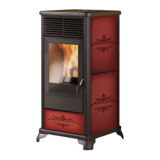
- Page 35 • S’assurer que le poêle est positionné et allumé par un CAT Il rivestimento esterno in ceramica è disponibile in tre varianti agréé par Edilkamin (Centre d’Assistance Technique) selon les di colore: bordeaux, cuir et parchemin. indications de la présente notice ; conditions du reste indispen- sables pour la validation de la garantie.
- Page 36 DIMENSIONS DEVANT DERRIÈRE Air de combustion Ø 40 mm sortie fumées Ø 80 mm CÔTÉ PLAN sortie fumées Ø 80 mm - 36...
-
Page 37: Caractéristiques
CARACTÉRISTIQUES • CARTE ÉLECTRONIQUE Prise RS323 RPM fumées batterie tampon cr2032 Réseau 230 vac 50Hz +/-10% Mot. Exp. Fumées Legenda: IN T J Termocoppia J Vis sans fi n T Amb Sonda ambiente RPM Giri esp fumi TM Termostato sicurezza P Pressostato sicurezza Ventilation DISPOSITIFS DE SÉCURITÉ... -
Page 38: Caractéristiques Électriques
(Avant d’effectuer toute opération d’entretien, débrancher l’appareil du réseau d’alimentation électrique). Les données mentionnées ci-dessus sont indicatives et relevées lors de la certifi cation effectuée par un organisme agréé. EDILKAMIN s.p.a. se réserve le droit de modifi er ses produits à son gré sans préavis et sans appel. - 38... -
Page 39: Installation
Le mauvais état du circuit de terre peut provoquer des pro- Dans ce cas, ne pas allumer l’appareil avec le système de blèmes de fonctionnement dont Edilkamin ne sera pas respon- sécurité désactivé. Si le problème n’est pas réglé, contacter le sable. - Page 40 INSTALLATION SORTIE DES FUMÉES CLASSICA est prédisposé pour le raccordement du conduit de sortie des fumées par le dessus, par l’arrière. La fi g. 1 représente le poêle dans l’état où il se trouve après avoir été déballé. Pour permettre le branchement de la sortie des fumées par l’arrière, retirez la coude de raccord Pour permettre de raccorder la sortie des fumées depuis le haut fi...
- Page 41 ASSEMBLAGE REVÊTEMENT Fig. 1 Cette fi gure représente le poêle dans l’état où il se trouve après avoir été déballé. Les pièces indiquées ci-dessous sont en revanche emballées à part. • 1 élément frontal inférieur en céramique (E - fi g. 5) •...
- Page 42 Centre d’Assistance Technique (CAT) CLASSICA est conçu et programmé pour brûler des granulés agréé par Edilkamin , conformément à la norme UNI 10683. en bois de 6 mm de diamètre environ. Les granulés sont des combustibles qui se présentent sous la Cette norme indique les opérations de contrôle à...
- Page 43 MODE D'EMPLOI PANNEAU SYNOPTIQUE INDICATION DE L’ÉCRAN Indique le fonctionnement du ventilateur. Phase d’arrêt en cours, durée d'environ 10 minutes ON AC Poêle en première phase d’allumage, charge- Indique le fonctionnement du motoréducteur de char- ment des granulés et attente de l'allumage de la gement des granulés.
-
Page 44: Fonctionnement Manuel
MODE D'EMPLOI ALLUMAGE Lorsque la chaudière est en stand-by, (après avoir vérifi é que Il est possible d’augmenter la température souhaitée en le creuset est propre), appuyer sur la touche pour lancer appuyant sur la touche ou de la diminuer en appuyant sur la procédure d’allumage. - Page 45 MODE D'EMPLOI CONFIGURATION : HORLOGE ET PRO- Appuyer sur SET, pour poursuivre la programmation pour Pr1/ GRAMMATION HEBDOMADAIRE Pr2/Pr3, ou sur « ESC », pour quitter la programmation. Appuyer sur la touche SET pendant 5 secondes afi n d’entrer dans le menu de programmation, puis un écran affi che le mes- •...
-
Page 46: Entretien Quotidien
• Extraire la partie supérieure interne (3 - fi g. C) et renverser les résidus dans le tiroir de la cendre (2 - fi g. B). La partie supérieure interne est un composant sujet à usure, Edilkamin ne répond pas des ruptures éventuelles de ce dernier, d’autant plus si la rupture a eu lieu lors de l’extraction ou du repositionne-... - Page 47 NE PAS TENTER D’ÉTEINDRE LE FEU AVEC DE L’EAU ! Demander successivement la vérifi cation de l’appareil de la part d’un Centre d’Assistance Technique (CAT) agréé par Edilkamin et faire vérifi er la cheminée par un technicien agréé. - 47...
- Page 48 CONSEILS EN CAS D’ÉVENTUELS PROBLÈMES En cas de problèmes, le poêle s’arrête automatiquement en effectuant l’opération d’extinction et l’écran affi che une ins- cription concernant les raisons de l’extinction (voir les différentes messages ci-dessous). Ne jamais débrancher la fi che pendant la phase d’extinction due à un blocage. Si un blocage se produit, pour redémarrer le poêle il faut laisser se dérouler la procédure d’extinction (10 minutes avec retour sonore), puis appuyer sur la touche Ne pas rallumer le poêle avant d’avoir vérifi...
-
Page 49: Liste De Contrôle
LISTE DE CONTRÔLE À intégrer avec la lecture complète de la fi che technique Pose et installation • Mise en service effectuée par le revendeur agréé qui a délivré la garantie. • Aération dans la pièce. • Le conduit de fumée/conduit de cheminée reçoit seulement l’évacuation du poêle. •... - Page 50 A través del vendedor, en el número verde o en el sitio internet www.edilkamin.com puede encontrar el nominativo del Centro de Asistencia técnica más cercano.
-
Page 51: Principio De Funcionamiento
• El cristal puede limpiarse en FRÍO con el producto adecuado en tres colores diferentes: burdeos, cuero y pergamino. (por ej. GlassKamin Edilkamin) y un paño. • No limpie en caliente. • Asegurarse de que la estufa es colocada y encendida por el VENDEDOR habilitado Edilkamin (según las indicaciones... - Page 52 DIMENSIONES FRENTE PARTE TRASERA Aire combustión 40 mm Ø Salida humos Ø 80 mm LADO PLANTA Salida humos Ø 80 mm - 52...
-
Page 53: Dispositivos De Seguridad
APARATOS ELECTRÓNICOS • FICHA ELECTRÓNICA Toma RS323 RPM humos bateria compensadora cr2032 Red 230 Vac 50Hz +/-10% fuse 2A Mot. exp. humos Legenda: IN T J Termocoppia J Cóclea Res encendido T Amb Sonda ambiente RPM Giri esp fumi TM Termostato sicurezza P Pressostato sicurezza Ventilación DISPOSITIVOS de SEGURIDAD... - Page 54 Los datos presentados más arriba son estimativos y han sido obtenidos en la fase de certifi cación en el organismo notifi cado. EDILKAMIN s.p.a. se reserva modifi car sin previo aviso los productos y a su entero juicio. - 54...
-
Page 55: Instalación
La inefi ciencia del circuito de tierra de poner en marcha la máquina. La estufa ha sido diseñada provoca el mal funcionamiento del cual Edilkamin no se hará para funcionar con cualquier condición climática. En caso de responsable. - Page 56 INSTALACIÓN SALIDA DE LOS HUMOS CLASSICA está preparada para conectar el tubo de salida de los humos en la parte trasera o en la parte superior. La fi g. 1 muestra la estufa en el estado en que está después de haberla desembalado.
- Page 57 MONTAJE DEL REVESTIMIENTO Fig. 1 Esta fi gura representa la estufa en el estado en que se encuentra después de haberla desembalado. Las piezas indicadas a continuación están embaladas aparte. • n°l frente inferior cerámico (E - fi g. 5) •...
-
Page 58: Instrucciones De Uso
NO permite la activación de la garantía. través de análisis de laboratorio, dejaría sin efecto la garantía. EDILKAMIN ha proyectado, probado y programado sus pro- Para más información, consultar la página web www.edilka- pios productos para que garanticen las mejores prestaciones min.com. -
Page 59: Indicaciones Del Display
INSTRUCCIONES DE USO PANEL SINÓPTICO INDICACIONES DEL DISPLAY Indica el funcionamiento del ventilador. Fase de apagado en curso, duración cerca de 10 minutos ON AC Estufa en primera fase de encendido, carga Indica el funcionamiento del motoreductor carga de pellet y encendido llama pellet. - Page 60 INSTRUCCIONES DE USO ENCENDIDO FUNCIÓN CONFORT CLIMA Con la estufa en stand-by (después de haber verifi cado que Función para instalaciones de estufas en ambientes de pequeña embargadura o, en media estación, donde el funcionamiento en el crisol está limpio) pulsar la tecla , empieza el proceso potencia mínima da un calentamiento excesivo.
- Page 61 INSTRUCCIONES DE USO PROGRAMACIÓN: RELOJ Y PROGRAMA- CIÓN SEMANAL • Pr 1: Este es el programa n° 1, en éste se programa un hora- Pulsar durante 5” la tecla SET, se entra en el menú de progra- rio de encendido, un horario de apagado y los días a los cuales mación y aparece en el display “”TS”.
-
Page 62: Mantenimiento Diario
• Extraer el plafond superior (3 - fi g. C) y verter los residuos en el cajón de las cenizas (2 - fi g. B). El plafond superior es un elemento sujeto a desgaste, Edilkamin no podrá responder de las roturas de dicho elemento, tanto menos si se rompe al quitarlo o ponerlo en su sitio. - Page 63 MANTENIMIENTO MANTENIMIENTO ESTACIONAL (a cargo del CAT - centro de asistencia técnica) Consiste en la: • Limpieza general interna y externa • Realizar una limpieza cuidadosa de los tubos de intercambio situados en el interior de la rejilla de salida del aire caliente que se encuentra ubicada en la parte superior del frontal de la estufa.
- Page 64 CONSEJOS PARA POSIBLES INCONVENIENTES En caso de problemas la estufa se para automáticamente efectuando la operación de apagado y en la pantalla se visualiza una anotación relativa a la motivación del apagado (ver abajo las diferentes indicaciones). No desconecte nunca el enchufe durante la fase de apagado por bloqueo. En caso de que se produzca un bloqueo, para volver a poner en marcha la estufa es necesario dejar acontecer el proceso (15 minutos con prueba de sonido) y luego pulsar la tecla No vuelva a poner en funcionamiento la estufa antes de haber verifi...
- Page 65 LISTA DE COMPROBACIÓN A completar con la lectura completa de la fi cha técnica Colocación e instalación • Instalación realizada por el Distribuidor habilitado que ha expedido la garantía • El canal de humo • El tubo de salida de humos recibe sólo la descarga de la estufa •...
- Page 66 Anfragen mitgeteilt und für den Fall von etwaigen Wartungseingriffen zur Verfügung gestellt werden; - Die abgebildeten Details sind graphisch und geometrisch unverbindlich. Hiermit erklärt die Firma EDILKAMIN S.p.A., Firmensitz in Via Vincenzo Monti 47 - 20123 Mailand - Steuernummer und USt-Nr. P.IVA 00192220192 Der hier beschriebene Pelletofen entspricht der EU-Richtlinie 305/2011 (CPR) und der harmonisierten Europäischen Norm EN...
- Page 67 Erzeugnis (z.B. GlassKamin Edilkamin) und einem Tuch gereinigt werden. Die äußere Keramikbeschichtung ist in drei Farbausführungen • Sicherstellen, dass der Heizofen durch ein von Edilkamin erhältlich: bordeaux, ledereffekt, Pergamen. zugelassenes CAT (Technisches Kundendienst-Center) gemäß den Angaben in diesem Datenblatt, die zudem für die Vali- dierung der Garantie unverzichtbare Voraussetzungen sind, aufgestellt und eingeschaltet wird.
- Page 68 ABMESSUNGEN VORDERSEITE RÜCKSEITE Ø 40 mm Brennluft Ø 80 mm Rauchabzug SEITE GRUNDRISS Ø 80 mm Rauchabzug - 68 - 68...
- Page 69 ELEKTROAPPARATE • PLATINE Anschluss RS323 Flusssensor RPM Umdrehungen Rauchgasgebläse pufferbatterie cr2032 netz 230 Vac 50Hz +/-10% fuse 2A Rauchabzugsmotor Channeling Innensockel Förderschnecke belüftung Channeling Rückseite des Ofens Steckdose Abluft- Erholung Belüftung im Lüftungsleitungen SICHERHEITSVORRICHTUNGEN SERIELLER PORT • THERMOELEMENT: Am seriellen RS232 Ausgang mit entsprechendem Kabel (Cod. Ermittelt die Rauchgastemperatur am Abzug.
- Page 70 (Vor Wartungsmaßnahmen stets bedenken, die Stromversorgung zu trennen) Bei den oben genannten Daten handelt es sich um Richtwerte. EDILKAMIN s.p.a. behält sich das Recht vor, die Produkte ohne Vorankündigung und nach eigenem Ermessen zu ändern. - 70...
- Page 71 überprüfen. Eine nicht wirksame Erdung führt zu einem eingezogen werden (z. B. Nirosta zu 80 mm Durchmesser). fehlerhaften Betrieb, für den Edilkamin keine Haftung über- Alle Rohrabschnitte müssen inspizierbar sein. Die Schornstei- nimmt. Die Versorgungsleitung muss einen der Leistung des ne und die Rauchabzüge, an die Festbrennstoff-Verbraucher...
- Page 72 INSTALLATION RAUCHABZUG CLASSICA ist zum Anschluss des Rauchabzugsrohrs an Ober- seite, bzw. konzipiert. Abbildung 1 stellt den Ofen in dem Zustand dar, in dem er sich nach dem Auspacken befi ndet. Um den Anschluss des Abgasrohr uf der Rueckseite zu ermoe- glichen muss er Bogen entfernt werden.
-
Page 73: Montage
MONTAGE Abb 1 Diese Abbildung stellt den Ofen in dem Zustand dar, in dem er sich nach dem Auspacken befi ndet. Nachstehende Teile werden getrennt verpackt: • 1 unteres Frontpaneel aus Keramik (E - Abb. 5) • 4 Seitenpaneele aus Keramik (F - Abb. 6) •... - Page 74 Die Verwendung von anderen Materialien (auch Holz), die per Laboranalyse nachgewiesen werden kann, führt zum Sollte das erste Anfeuern nicht durch ein autorisiertes techni- Verfallen der Garantie. EdilKamin hat seine Erzeugnisse sches Kundendienstcenter erfolgen, kann die Garantie nicht dahingehend entwickelt, geprüft und programmiert, dass sie aktiviert werden.
-
Page 75: Display Anzeige
GEBRAUCHSANWEISUNG BEDIENFELD DISPLAY ANZEIGE Zeigt an dass der Ventilator im Betrieb ist Ausschaltphase läuft, Dauer etwa10 Minuten ON AC Ofen in erster Anzündphase, Beladen mit Pellets und Warten auf das Zünden Zeigt an dass der Schneckenmotor im Betrieb ist der Flamme ON AR Ofen in zweiter Anzündphase, Start der Verbrennung im ordentlichen Rhythmus... - Page 76 GEBRAUCHSANWEISUNG EINSCHALTEN Mit dem Ofen auf Stand-by (nachdem man überprüft hat, dass AUTOMATIKBETRIEB auszuwählen, die Set Taste drücken und auf dem Display z.B. 20°C einstellen. der Tiegel sauber ist), wird durch Drücken der Taste Die Temperatur kann durch Drücken der entsprechenden Taste Einschalt- bzw.
- Page 77 GEBRAUCHSANWEISUNG EINSTELLUNG: UHRZEIT UND WÖCHENT- LICHE PROGRAMMIERUNG 5” lang die SET Taste betätigen, man hat nun Zugang • Pr 1: Dies ist das Programm Nr. 1, hier wird die Uhrzeit zum Einschalten eingestellt, die Uhrzeit zum Ausschalten und die zum Programmiermenü und es erscheint die Aufschrift Wochentage, an denen das Programm in der Zeitspanne Pr 1 “TS”.
-
Page 78: Tägliche Wartung
• Decke heraus ziehen (3 - Abb. C) und Reste in den Ascheka- sten schütten (2 - Abb. B). Die Decke ist ein Verschleißteil, deshalb haftet Edilkamin nicht, wenn dieses Teil zu Bruch geht, insbesondere dann, wenn dies beim Herausziehen oder Ein- schieben geschieht. - Page 79 WARTUNG JÄHRLICHE WARTUNG (Aufgabe des CAT – techni- schen Kundendienstes) Maßnahmen: • Allgemeine Innen- und Außenreinigung • Sorgfältige Reinigung der Austauschrohre im Inneren des Luftau- trittsgitters, das sich vorne an der Oberseite des Ofens befi ndet • Sorgfältige Reinigung und Entkrustung des Tiegels und des entsprechenden Tiegelraums •...
-
Page 80: Troubleshooting
TROUBLE SHOOTING Im Störungsfall wird der Ofen automatisch gestoppt, indem das Abschaltverfahren durchgeführt wird und auf Display erscheint eine Aufschrift, die den Grund der Abschaltung angibt (siehe unten die verschiedenen Meldungen). Während der Abschaltphase wegen Blockierung niemals den Netzstecker ziehen. Kommt es zu einer Blockierung, muss der Ofen, bevor er wieder eingeschaltet werden kann, zunächst das Abschaltverfah ren durchführen (15 Minuten mit Tonsignal). - Page 81 CHECKLISTE Mit dem vollständigen Lesen der technischen Beschreibung zu ergänzen Einbau und Inbetriebnahme • Inbetriebnahme durch ein zugelassenes Servicecenter, das die Garantie ausgestellt hat • Belüftung des Raums • Der Rauchkanal bzw. Schornstein empfängt nur den Abzug des Ofens • Der Rauchabzug weist auf: höchstens 3 Kurven höchstens 2 Meter in der Waagerechten •...
- Page 82 Voordat u het gebruikt, vragen wij u dit boekje aandachtig te lezen, zodat u het toestel optimaal en in alle veiligheid kunt gebrui- ken. Voor meer informatie, neem contact op met de DEALER waar u het toestel heeft gekocht of ga op onze website www.edilkamin. com naar het menu CENTRI ASSISTENZA TECNICA (dealers).
- Page 83 (bijv. GlassKamin Edilkamin) en een doek. De externe keramieke bekleding van de ketel is beschikbaar in • Controleer of de kachel door de erkende Edilkamin dealer drie kleuren: bordeauxrood, lederkleuring, perkamentkleu- volgens de aanwijzingen van dit blad geplaatst en ontstoken rig.
- Page 84 AFMETINGEN VOORKANT ACHTERKANT verbrandingslucht Ø 40 mm rookgasafvoer Ø 80 mm ZIJKANT ONDERKANT rookgasafvoer Ø 80 mm - 84...
- Page 85 CARATTERISTICHE • ELEKTRONISCHE KAART Contact RS323 RPM rook Stroomsensor bufferbatterij cr2032 Netwerk 230 Vac 50Hz +/-10% fuse 2A Mot. Verw. Rook channeling interne socket Vulschroef Ventilatie channeling achterkant van de kachel uitlaat herstel geleide ventila- ventilatie interne tiekanalen BEVEILIGING • THERMOKOPPEL: SERIËLE POORT Op de seriële poort RS232 kunt u met een speciaal kabeltje Bevindt zich op de rookgasafvoer en meet de temperatuur van...
- Page 86 (Trek altijd de stekker uit vooraleer u enig onderhoud uitvoert). De hierboven vermelde gegevens zijn indicatief. EDILKAMIN s.p.a. behoudt zich het recht voor om zonder voorafgaandelijke kennisgeving naar eigen goeddunken wijzi- gingen aan te brengen aan de producten. - 86...
- Page 87 Edilkamin acht zich niet verantwoordelijk geveegd worden (controleer of in uw land dit per wet geregeld voor storingen in de functionering als gevolg van een slecht is).
- Page 88 INSTALLATIE ROOKGASAFVOER De rookgasafvoer bij CLASSICA kan bovenaan, achteraan aangesloten worden. Figuur 1 beeldt de kachel af in de staat waarin deze zich be- vindt na het uitpakken. Om de rookgasafvoer achteraan te kunnen aansluiten, moet de gebogen verbindingsbuis worden geëlimineerd. Om de verbinding te kunnen maken met de rookafvoer vanaf Afb.
- Page 89 ASSEMBLAGE Afb. 1 Deze fi guur beeldt de kachel af in de staat waarin deze zich bevindt na het uitpakken. De onderstaande onderdelen zijn afzonderlijk verpakt. • 1 keramisch paneel onderaan (E - Afb 5) • 4 keramische zijpanelen (F -Afb 6) •...
- Page 90 CLASSICA is ontworpen en geprogrammeerd voor de ver- Edilkamin in overeenstemming met de norm UNI 10683. branding van houtpellets met een doorsnede van ongeveer 6 Deze norm geeft de controlehandelingen aan die moeten...
- Page 91 GEBRUIKSAANWIJZING SYNOPTISCH PANEEL AANDUIDING OP HET DISPLAY Geeft aan dat de ventilator werkt Het toestel bevindt zich in de uitschakelings fase, duurt ongeveer 10 minuten ON AC Kachel in de eerste ontstekingsfase, vullen Geeft aan dat de reductiemotor van de pellettoever met pellets en wachten tot het ontsteken van werkt de vlam...
- Page 92 GEBRUIKSAANWIJZING ONTSTEKING Om de AUTOMATISCHE modus in te stellen, druk op de toets Met de kachel in stand-by (nadat u gecontroleerd heeft of de en stel het display bijvoorbeeld in op 20°C. De gewenste temperatuur kan verhoogd worden door op de toets vuurpot schoon is), druk op de toets om de ontstekingspro- cedure te starten.
- Page 93 GEBRUIKSAANWIJZING INSTELLING: KLOK EN WEKELIJKSE PRO- GRAMMERING • Pr 1: Dit is het eerste programma, waarin een ontstekingsuur Druk gedurende 5 seconden op de toets SET om het program- en een uitschakelingsuur ingesteld worden, alsook de dagen en meringsmenu te openen. Op het display verschijnt de aandui- de tijdspanne waarop de instelling toegepast moet worden Pr 1.
-
Page 94: Dagelijks Onderhoud
C) uittrekken en de resten uitgieten in de aslade (2 - Afb. B). Het plafond is een onderdeel dat onderhevig is aan slijtage, Edilkamin is niet aansprakelijk voor het breken ervan, des te meer als de breuk optreedt tijdens het uittrekken of het op- nieuw plaatsen op de plaats. - Page 95 ONDERHOUD SEIZOENSGEBONDEN ONDERHOUD (bestemd voor de dealer) Dit bestaat uit: • Volledige interne en externe reiniging • Grondige reiniging van de buizen in het rooster van de warme- luchtuitgang van de kachel • Grondige reiniging en het verwijderen van de afzettingen van de vuurhaard en de desbetreffende ruimte •...
- Page 96 ADVIES VOOR MOGELIJKE PROBLEMEN In geval van problemen, wordt de kachel automatisch uitgeschakeld, waarbij de uitdovingsprocedure uitgevoerd wordt. Op het display verschijnt er een aanduiding met betrekking tot de reden van de uitdoving (zie hieronder voor de verschil- lende aanduidingen). Koppel nooit de stekker los tijdens de uitdovingsfase wanneer deze het gevolg is van een blokkering.
- Page 97 CHECK LIST Te integreren met een complete bestudering van het technische blad Plaatsing en installatie • De inbedrijfstelling door een erkende Dealer die het garantiebewijs. • Ventilatie van de installatieruimte. • Het rookkanaal/de schoorsteen worden uitsluitend voor de kachel gebruikt. •...
- Page 98 à disposição em caso de eventual intervenção de manutenção; - os particulares representados são grafi camente e geometricamente indicativos. A abaixo assinada EDILKAMIN S.p.A. com sede legal em Via Vincenzo Monti 47 - 20123 Milão - cód. Fiscal P.IVA 00192220192 Declara sob a própria responsabilidade que: A estufa a pellet abaixo indicada é...
- Page 99 FRIO. • O vidro pode ser limpo a FRIO com o produto apropriado aplicado com um pano (por ex.: Glasskamin da Edilkamin). • Não limpar a quente. • Certifi car-se que a estufa seja colocala e acesa por CAT habilitado Edilkam (Centro Assistência Técnica) conforme as...
- Page 100 DIMENSÕES FRENTE RETRO conduto tomada de ar 40 mm Ø conduto fumos Ø 80 mm LADO PLANTA conduto fumos Ø 80 mm - 100 - 100...
-
Page 101: Dispositivos De Segurança
APARELHOS ELETRÓNICOS • FICHA ELECTRÓNICA tomada RS323 pilha de lítio cr2032 Rede 230 Vac 50Hz +/-10% fundidas 2A Mot. exp. humos Legenda: IN T J Termocoppia J Res encendido T Amb Sonda ambiente RPM Giri esp fumi TM Termostato sicurezza P Pressostato sicurezza ventilador DISPOSITIVOS DE SEGURANÇA... - Page 102 (Antes de efectuar qualquer tipo de manutenção, desintroduzir o aparelho da rede de alimentação eléctrica) Os dados apresentados acima são os obtidos por uma entidade notifi cada na fase de certifi cação. EDILKAMIN s.p.a. reserva-se de alterar sem pré-aviso os produtos e a sua opinião. - 102...
- Page 103 A não efi ciência do circuito de terra provoca o mau funciona- rança que levarão ao desligamento da caldeira térmica. Neste mento do qual Edilkamin não pode ser encarregada. caso, não deixar o aparelho funcionar com os dispositivos de segurança desabilitados, caso este problema persista contactar DISTÂNCIAS DE SEGURANÇA ANTI-INCÊNDIO...
- Page 104 INSTALAÇÃO SAÍDA DOS FUMOS CLÁSSICA é predisposta para a conexão do tubo de saída dos fumos por trás e por cima. Na fi g. 1 é apresentada a estufa como se encontra depois de desembalada. Para permitir a conexão da saída de fumos traseira, eliminar a curva do conector.
- Page 105 MONTAGEM DO REVESTIMENTO Fig. 1 Nesta fi gura é apresentada a estufa como se encontra depois de desembalada. As seguintes peças vêem embaladas separadas: • 1 peça frontal inferior de cerâmica (E - fi g. 5). • 4 painéis laterais de cerâmica (F - fi g. 6). •...
-
Page 106: Instruções De Uso
fi nais devem ser realizados por um centro CLASSICA é projectada e programada para queimar pellet de de assistência técnica autorizado pela Edilkamin (CAT) a madeira de diâmetro de 6 mm cerca. respeitar a norma UNI 10683. - Page 107 INSTRUÇÕES DE USO PAINEL SINÓPTICO INDICAÇÕES DO DISPLAY Indica o funcionamento do ventilador Fase de desligamento em curso, dura cerca de 10 minutos ON AC Caldeira na primeira fase de acendimento, Indica o funcionamento do motorredutor de carrega- carregamento de pellet e a aguardar a mento de pellets chama acender-se ON AR...
- Page 108 INSTRUÇÕES DE USO ACENDIMENTO FUNÇÃO COMFORT CLIMA Com a caldeira em stand-by, (depois de ter-se assegurado que o Uma função adequada no caso de caldeira instalada em am- bientes de pequena metragem ou, nas meias estações, nas quais cadinho está limpo), pressionar a tecla , inicia o proces- mesmo o funcionamento na potência mínima causaria um so de acendimento.
- Page 109 INSTRUÇÕES DE USO CONFIGURAÇÃO: RELÓGIO E PROGRA- MAÇÃO SEMANAL • Pr 1: Este é o programa n° 1, nessa faixa confi guram-se: Manter durante 5” a tecla SET pressionada para entrar a hora para acender-se, a hora para apagar-se, e os dias no menu de programação e aparecerá...
-
Page 110: Manutenção Diária
• Retirar o tecto (3 - fi g. C) e deitar os resíduos à caixa das cinzas (2 - fi g. B). O tecto é uma peça sujeita a desgaste, a Edilkamin não poderá responder por quebras no mesmo, muito menos caso se parta durante a sua retirada ou recolocação no seu lugar. - Page 111 MANUTENÇÃO MANUTENÇÃO DE ESTAÇÃO (ao encargo do CAT - centro assistência técnica) Consiste em: • Limpeza geral interna e externa • Atenta limpeza dos tubos de permuta postos no interior da grelha de saída de ar quente instalada, por sua vez, na parte superior frontal da estufa.
- Page 112 CONSELHOS PARA POSSÍVEIS INCONVENIENTES Em caso de problemas a estufa pára automaticamente desligando-se e no display se visualiza uma escrita relativa à moti- vação do porque desligar (ver abaixo as várias sinalizações). Nunca desligar a fi cha enquanto se desliga por bloqueio. Caso de bloqueio, para reiniciar a estufa é...
- Page 113 CHECK LIST A integrar com a leitura completa da fi cha técnica Posa e instalação • Colocação em serviço efectuada pelo CAT habilitado que emitiu a garantia e o livro de manutenção • Arear o local • O canal de fumo / a chaminé revebe apenas a descarga da estufa •...
- Page 114 - zawartość instrukcji od strony grafi cznej i geometrycznej ma charakter poglądowy. Firma EDILKAMIN S.p.A.. z siedzibą w Via Vincenzo Monti 47 - 20123 Milano - Nr NIP 00192220192 Piec na pelet drzewny wymieniony poniżej jest zgodny z Normą UE 305/2011 (CRP) oraz ze zharmonizowaną Norm Europejską...
-
Page 115: Zasada Działania
Ceramiczna obudowa korpusu dostępna jest w trzech wersjach • Upewnić się, że piecyk zostanie ustawiony i uruchomio- kolorystycznych: bordowej, jasno brązowej lub beżowej. ny przez serwis fi rmy Edilkamin, zgodnie ze wskazaniami zawartymi w niniejszej karcie produktowej. Jest to warunek niezbędny dla aktywacji gwarancji. - Page 116 WYMIARY PRZÓD TYŁ Ø 4 cm powietrze do spalania Ø 8 cm odprowadze- nie spalin RZUT Ø 8 cm odpro- wadzenie spalin - 116 - 116...
-
Page 117: Opis Techniczny
OPIS TECHNICZNY • KARTA STERUJĄCA Legenda: IN T J Termocoppia J T Amb Sonda ambiente RPM Giri esp fumi TM Termostato sicurezza P Pressostato sicurezza URZĄDZENIA ZABEZPIECZAJĄCE PORT SZEREGOWY • TERMOPARA: Na wyjściu szeregowym RS232 przy użyciu odpowiedniego przewo- znajdująca się na odprowadzeniu spalin, odczytuje ich du (kod 640560) autoryzowany serwis może zainstalować... - Page 118 2) uwaga: interwencje na komponentach znajdujących się pod napięciem, konserwacje i/lub kontrole muszą być wyko- nywane przez wykwalifi kowany personel. (Przed wykonaniem jakiejkolwiek czynności konserwacji należy odłączyć piecyk od zasilania elektrycznego). Powyższe dane są orientacyjne. EDILKAMIN zastrzega sobie prawo do wprowadzania, bez uprzedzenia, zmian mających na celu polepszenie wydajności. - 118 - 118...
- Page 119 Niesprawne działanie obwodu uziemienia może być powodem Piecyk jest przeznaczony do użytkowania w każdych warun- złego funkcjonowania piecyka, za które Edilkamin nie ponosi kach klimatycznych. W przypadku szczególnych warunków żadnej odpowiedzialności. np. silnego wiatru moga zadziałać systemy zabezpieczające powodujące wyłączenie piecyka.
- Page 120 INSTALACJA ODPROWADZENIE SPALIN CLASSICA posiada odprowadzenie spalin z tyłu piecyka lub do góry. Na rys. 1 pokazano piecyk w stanie w jakim się znajduje po rozpakowaniu. Aby umożliwić podłączenie odprowadzenia spalin z tyłu pieca należy usunąć kolano przyłączeniowe. Żeby umożlwić odprowadzenie spalin do góry należy: rys.
-
Page 121: Montaż Obudowy
MONTAŻ OBUDOWY Rys. 1 Na tej ilustracji pokazano piecyk w stanie w jakim się znajduje po rozpakowaniu. Niżej wymienione elementy są natomiast pakowane osobno. • 1 dolny front ceramiczny (E - rys. 5) • 4 boczne płyty ceramiczne (F - rys. 6) •... -
Page 122: Instrukcja Obsługi
Szczegółowe informacje znajdą Państwo na stronie www. przedmiotowe urządzenie. edilkamin.com Firma EdilKamin zaprojektowała, przetestowała i zaprogramowała swoje produkty, aby gwarantowały one Przy kilku pierwszych rozpaleniach może pojawić się nie- najlepszą wydajność przy opalaniu peletem o następujących przyjemny zapach farby, który w krótkim czasie zanika. -
Page 123: Wskazania Na Wyświetlaczu
INSTRUKCJA OBSŁUGI PANEL STERUJĄCY WSKAZANIA NA WYŚWIETLACZU wskazuje na działanie wentylatora Faza wygaszania w toku, czas trwania około 10 minut ON AC Piecyk w pierwszej fazie rozpalania, Wskazuje na działanie motoreduktora do załadunku załadunek peletu i oczekiwanie na płomień peletu ON AR Piecyk w drugiej fazie rozpalania, uruchomienie normalnego spalania... - Page 124 INSTRUKCJA OBSŁUGI ROZPALANIE Można zwiększyć żądaną temperaturę za pomocą klawisza Przy piecu w stand-by, (po sprawdzeniu, czy palnik jest lub zmniejszyć ją za pomocą klawisza czysty), wciśnij klawisz , uruchomi się procedura rozpala- Podcza pracy w trybie AUTOMATYCZNYM na wyświetlaczu nia.
- Page 125 INSTRUKCJA OBSŁUGI USTAWIANIE: ZEGARA ORAZ PROGRAMOWA- NIE TYGODNIOWE • Pr 1: To program nr 1, w tym przedziale określa się godzine rozpalenia nr 1, godzinę wygaszenia nr 1 oraz dni w których ma być używny przedziale czasowym nr Pr 1. Wciskaj przez 5 sekund klawisz SET, wejdziesz do menu pro- gramowania a na wyświetlaczu pojawi się...
- Page 126 • Wyjmij sklepienie paleniska (3 - rys. C) i wysyp osady do po- pielnika resztki do popielnika (2 - rys. B). Sklepienie paleniska rys. C jest komponentem ulegającym zużyciu, Edilkamin nie może odpowiadać za jego pęknięcia, tym bardziej wówczas kiedy pęknięcia powstają podczas wyciągania lub umieszczania go na miejscu.
- Page 127 - odłączyć zasilanie elektryczne - użyć gaśnicy CO - wezwać straż pożarną NIE PRÓBOWA UGASIĆ POŻARU WODĄ! Następnie poprosić o skontrolowanie piecyka autoryzowany serwis Edilkamin oraz o dokonanie przeglądu komina przez odpowiednie- go fachowca. - 127 - 127...
- Page 128 PORADY W PRZYPADKU WYSTĄPIENIA NIEPRAWIDŁOWOŚCI W przypadku wystąpienia problemów piecyk zatrzymuje się automatycznie, wykonując operację wygaszania, a na wyświetlaczu pojawia się komunikat określający przyczynę wyłączenia (zobacz poniżej różnego rodzaju komunikaty). Nigdy nie należy odłączać wtyczki podczas fazy wygaszania alarmowego. W przypadku wystąpienia blokady, w celu ponownego uruchomienia piecyka należy odczekać do momentu zakończenia procedury wygaszania (600 sekund z sygnalizacją...
-
Page 129: Lista Kontrolna
LISTA KONTROLNA Zapoznać się po dokładnym przeczytaniu karty technicznej Ustawienie i instalacja • Uruchomienie przez serwis, upoważniony do aktywowania gwarancji i przekazania karty konserwacji • Odpowiednie doprowadzenie powietrza do pomieszczenia • Kanał spalinowy dedykowany wyłącznie dla odbioru spalin z kotła •... - Page 130 w w w . e d i l k a m i n . c o m cod. 941104 .07.15/H - 130...
Need help?
Do you have a question about the ITALIANA CAMINI CLASSICA and is the answer not in the manual?
Questions and answers