Table of Contents
Advertisement
A
, A
, O
& M
M
SSEMBLY
DJUSTMENT
PERATION
AINTENANCE
ANUAL
P
B
B
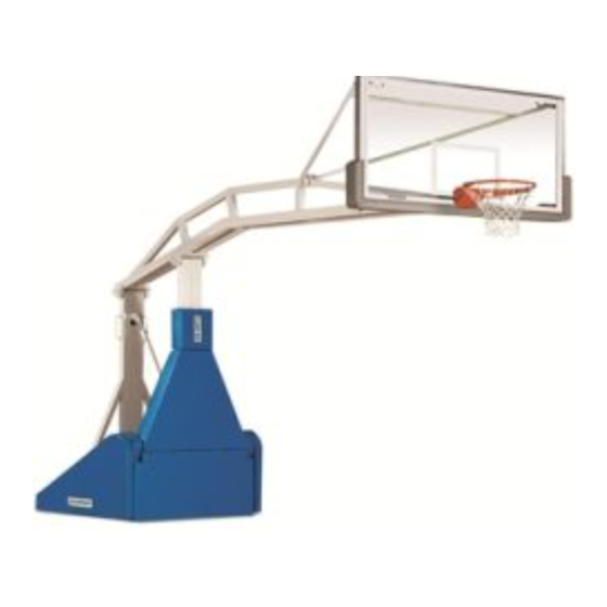
ORTABLE
ASKETBALL
ACKSTOP
No. 1535
INSTALLER NOTE:
Upon completion of the installation/assembly of this portable backstop,
make sure this instruction manual is in the possession of the owner or
facility manager, to save for future reference.
INST 00106 097
2011 PORTER ATHLETIC EQUIPMENT COMPANY. ALL RIGHTS RESERVED.
11-14-2011
Advertisement
Table of Contents

Related Manuals for Porter 1535


Summary of Contents for Porter 1535
- Page 1 Upon completion of the installation/assembly of this portable backstop, make sure this instruction manual is in the possession of the owner or facility manager, to save for future reference. INST 00106 097 2011 PORTER ATHLETIC EQUIPMENT COMPANY. ALL RIGHTS RESERVED. 11-14-2011...
- Page 2 Your athletes and spectators should enjoy thousands of hours of practice and competition on Porter equipment. This booklet is intended to be used for the initial set-up of your No. 1535 backstop, and as a guide for the safe use and maintenance of the unit. PLEASE READ THESE INSTRUCTIONS CAREFULLY AND COMPLETELY BEFORE BEGINNING THE SET-UP WORK, OR MAINTENANCE, OF THIS UNIT.
-
Page 3: Table Of Contents
TABLE OF CONTENTS ITEM / DESCRIPTION PAGE No. Assembly Details Parts List Assembly of Backboard, Goal, Swaybraces and Floor Jacks 6 – 11 Remove Shipping Clamp At This Time Assembly of Padding and Enclosure Panels 12 – 14 Assembly of Backboard Padding Adjustment of Spring-Loaded Mechanism 15 –... -
Page 4: Assembly Details
CAUTION ! 1535 PORTABLE BACKSTOP ASSEMBLY DETAILS... -
Page 5: Parts List
WARNING READ THESE ASSEMBLY AND OPERATING INSTRUCTIONS IN THEIR ENTIRETY, BEFORE ATTEMPTING TO UNPACK, ASSEMBLE, OR OPERATE THIS PORTABLE BACKSTOP, TO AVOID POSSIBLE INJURIES, OR DAMAGE TO THE EQUIPMENT. PARTS LIST 01535-500 01535-800 01535-108 Item No. Part No. Quantity Quantity Quantity Description 00208-000... - Page 6 No. 1535 PORTABLE ROLLAWAY BACKSTOP ASSEMBLY INSTRUCTIONS CAUTION BEFORE rolling this portable backstop onto the finished floor, check with the flooring manufacturer to ensure the finished floor will not be damaged due to the weight of this unit. When fully-assembled, this backstop will weigh as much as 2,525 pounds (1,145kg), and will exert a force of approximately 485 pounds per square inch (35kg per square centimeter).
- Page 7 NOTE CAUTION – DURING ASSEMBLY OF THIS BACKSTOP, IT IS OF EXTREME IMPORTANCE THAT THE BACKBOARD IS NOT DROPPED, IMPROPERLY TORQUED (BOLTS TIGHTENED BEFORE PLUMBING ALL ATTACHMENT POINTS), OR THE GLASS SECTION BE ALLOWED TO CONTACT OR STRIKE METAL PARTS. THE WARRANTY DOES NOT COVER BREAKAGE DURING INSTALLATION.
- Page 8 7. Lay backboard yoke frame (#5) Detail on the top side of the backstop "C" horizontal extension assembly, positioning upper ends of the yoke into the hinges in the upper corners backboard assembled in Step No. 6. Secure in place with two (2) 1/2" x 3" lg. hex head cap screws (#9), 1/2"...
-
Page 9: Remove Shipping Clamp At This Time
9. Remove the two goal mounting bolts assembled in Steps No. 3 & 4. 10. You are now ready to mount the goal. Carefully hold the goal (#3) against the face plate of the backboard (#1) and insert the two 3/8"... - Page 10 Detail "E" AFTER SETTING GOAL HEIGHT AT 10'-0", TURN LOCKING COLLAR DOWNWARD UNTIL IT BOTTOMS OUT ON BASE COLLAR. THEN TIGHTEN SET SCREW SECURELY. REPEAT FOR OTHER FLOOR JACK. 22 23 APPLY GREASE TO THREADED ROD ON BOTH LEVELING ASSEMBLIES FOR EASE OF OPERATION SECTION "A-A"...
- Page 11 Detail "F" LIFT UP ON LEVER TO RELEASE BRAKE PUSH DOWN ON LEVER TO LOCK BRAKE...
-
Page 12: Assembly Of Padding And Enclosure Panels
ASSEMBLE PADDING AND ENCLOSURE PANELS TO FRAME AS FOLLOWS 23. Start by assembling the wrap around pad (#34) to front of side frame just under pillow block using a 5/16" x 3/4" long phillips flat head machine screw (#19) through the flap grommet. Remove peel and stick tape on Velcro attached to pad. Wrap pad firmly around bearing and vertical support and press downward firmly to insure that pad is secured in place. - Page 13 24. Mount front mast pad assembly (#37) to the front mast using six (6) 1/4" x 4" hex head lag screws (#18). See Detail “H”. 25. Assemble top mast pad (#38) above front mast pad assembly (#37) from Step No. 24 using four (4) 1/4" x 4" hex head lag screws (#18).
- Page 14 See Page 4. 29. Next, locate lower spring cover (#33) (which has Porter logo) just under pillow blocks. Check fit, then remove tape backing from peel and stick Velcro pile and attach to base tubes to hold cover in position. See Page 4.
-
Page 15: Adjustment Of Spring-Loaded Mechanism
ADJUSTMENT OF SPRING-LOADED MECHANISM FOR EASE OF RAISING AND LOWERING BACKBOARD The tension springs on this unit have been pre-adjusted at the factory for proper raising and lowering of the backboard. However, should it be necessary to adjust the springs after years of use, or with the addition of shot clocks, the following adjustment procedures should be followed. - Page 16 DIFFICULTY IN RAISING THE UNIT (REFER TO DETAIL “J”) 1. Loosen (turn clockwise) the two jam nuts (A) approximately six (6) turns. 2. Loosen (turn counterclockwise) the two jam nuts (B) approximately one (1) turn. 3. Tighten (turn clockwise) jam nuts (C) no more than two (2) turns. 4.
- Page 17 7. At this point the springs may be swapped out as necessary depending on the system setup. The chart below describes the type and quantity of springs recommended based on the amount of shot clock weight attached to the portable. The “Approximate Distance” column lists the approximate extended length of the spring (measured from hook to hook) of the spring when the portable is lowered and locked in the down position.
-
Page 19: Operating Procedures
OPERATING PROCEDURES FOR THE No. 1535 PORTABLE BACKSTOP TO RAISE UNIT TO PLAYING POSITION 1. Roll to the playing position while the unit is in the folded and locked position. 2. Raise rear cover slightly and press caster levers downward to lock casters and prevent the unit from rolling on the floor. -
Page 20: Warnings On Misuse Of Portable Backstops
WARNING DANGER / WARNING ON MISUSE OF PORTABLE BACKSTOPS (Published in Compliance with NCAA Comments on the Rules of Basketball) Read all warnings thoroughly before using this equipment. Failure to comply with the following instructions and warnings may result in serious injuries and/or property damage. A high degree of injury potential and severe liability problems exist when players or spectators are allowed to hang, sit or stand on the goal, backboard or support structure. - Page 21 01536-100 FLOOR ANCHOR SYSTEM FOR PAIR OF WORLD LEADER IN QUALITY SPORTS EQUIPMENT No. 01535-500 PORTABLE BACKSTOPS 2500 S. 25th AVENUE BROADVIEW, ILLINOIS 60155 B-1536-5 www.porter-ath.com...
- Page 22 01236-300 FLOOR ANCHOR SYSTEM FOR PAIR OF WORLD LEADER IN QUALITY SPORTS EQUIPMENT No. 01535-800 PORTABLE BACKSTOPS 2500 S. 25th AVENUE BROADVIEW, ILLINOIS 60155 B-1536-8 www.porter-ath.com...
- Page 23 TIE-DOWN AND LEVELERS FLOOR ANCHOR SYSTEM SUPPLIED WITH WORLD LEADER IN QUALITY SPORTS EQUIPMENT No. 01535-108 PORTABLE BACKSTOP 2500 S. 25th AVENUE BROADVIEW, ILLINOIS 60155 B-1536-10 www.porter-ath.com...
-
Page 24: Locating Portable Backstops On Playing Floor
LOCATING PORTABLE BACKSTOPS LOCATING PORTABLE BACKSTOPS ON PLAYING FLOOR 48" 15" 3-POINT ARC LOCATE NAIL HOLE IN FLOOR, LOCATED ON CENTERLINE OF COURT, 63" IN FROM THE END BOUNDARY LINE 63" TO PROPERLY LOCATE A PORTABLE UNIT ON THE PLAYING FLOOR, DROP A PLUMB LINE FROM THE EXACT CENTER OF THE GOAL AND POSITION UNIT TO ALIGN WITH NAIL HOLE ON FLOOR. -
Page 25: Guarantee
Care has been taken to fabricate and install this equipment to provide years of safe, satisfactory use and trouble-free service. The key to satisfactory service from this equipment is proper operation and care. Should any malfunctions occur, please notify your supervisor and call your local Porter Dealer or Representative.
Need help?
Do you have a question about the 1535 and is the answer not in the manual?
Questions and answers