Table of Contents
Advertisement
Advertisement
Table of Contents

Related Manuals for Beckhoff CX50 0 Series


Summary of Contents for Beckhoff CX50 0 Series
- Page 1 Hardware Documentation CX50x0 Embedded-PC Version: Date: 2017-03-30...
-
Page 3: Table Of Contents
Table of contents Table of contents 1 Foreword .............................. 5 Notes on the documentation...................... 5 Safety instructions .......................... 6 Documentation issue status ...................... 7 2 Product overview............................ 8 Intended use ............................ 8 System Overview.......................... 9 CX5010 - Technical data ......................... 11 CX5020 - Technical data ......................... 12 Types ............................... 13 Architekture overview ........................ 15 Battery compartment ........................ 17 CF slot ............................. 19... - Page 4 Table of contents 5.5.1 SYSTEMINFOTYPE ...................... 69 5.5.2 PlcAppSystemInfo ...................... 71 6 Error handling and diagnostics...................... 72 Basic CPU module .......................... 72 6.1.1 LEDs on the basic CPU module .................. 72 6.1.2 LEDs of the power supply in K-bus mode................ 72 6.1.3 LEDs of the power supply in E-bus mode................
-
Page 5: Foreword
EP0851348, US6167425 with corresponding applications or registrations in various other countries. ® EtherCAT is registered trademark and patented technology, licensed by Beckhoff Automation GmbH, Germany Copyright © Beckhoff Automation GmbH & Co. KG, Germany. The reproduction, distribution and utilization of this document as well as the communication of its contents to others without express authorization are prohibited. -
Page 6: Safety Instructions
All the components are supplied in particular hardware and software configurations appropriate for the application. Modifications to hardware or software configurations other than those described in the documentation are not permitted, and nullify the liability of Beckhoff Automation GmbH & Co. KG. Personnel qualification This description is only intended for trained specialists in control, automation and drive engineering who are familiar with the applicable national standards. -
Page 7: Documentation Issue Status
Foreword Documentation issue status Version Changes Preliminary version First publication Changes on system interface N031 and DVI resolution Changes on temperature range and K-bus diagnosis Requirements for power supply added Notes on passive terminals and power supply added Notes on K-Bus diagnosis added UL requirements added Architecture overview added Chapter Types reworked... -
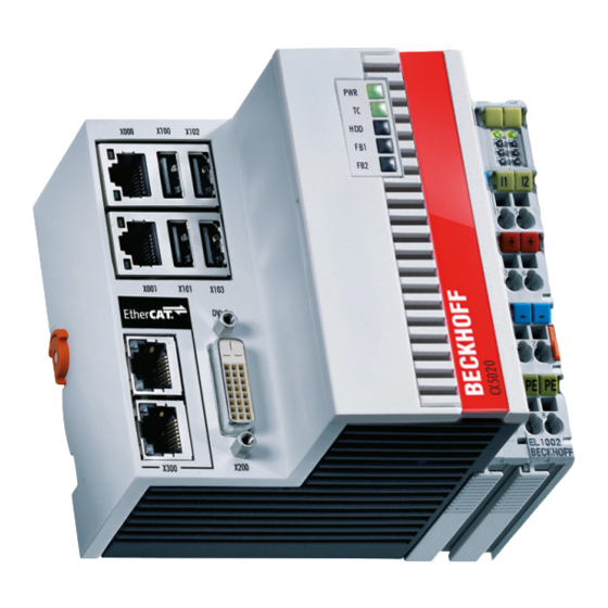
Page 8: Product Overview
Product overview Product overview Intended use The CX5010 / CX5020 device series is a modular control system designed for top-hat rail installation. The system is scalable, so that the required modules can be assembled and installed in the control cabinet or terminal box as required. -
Page 9: System Overview
PLC, Motion Control and visualisation As a DIN rail IPC and in conjunction with the TwinCAT software from Beckhoff, the CX50x0 offers the same functionality as large Industrial PCs. In terms of PLC, up to four virtual IEC 61131 CPUs can be programmed with up to four tasks each, with a minimum cycle time of 50 μs. - Page 10 The complete programming of PLC, Motion Control and visualization is transferable to all PC controls from Beckhoff, which is reassuring in cases where it becomes apparent during a project that more processing power is required after all. In this case a system with higher performance can be used.
-
Page 11: Cx5010 - Technical Data
-25 °C ... +60 °C/-40 °C ... +85 °C Relative humidity 95 % no condensation Vibration/shock resistant conforms to EN 60068-2-6/EN 60068-2-27/ 29 EMC immunity/emission conforms to EN 61000-6-2 / EN 61000-6-4 Protection class IP 20 Further Information: www.beckhoff.de/CX5010 CX50x0 Version: 1.9... -
Page 12: Cx5020 - Technical Data
-25 °C ... +60 °C / -40 °C ... +85 °C Relative humidity 95 % no condensation Vibration/shock resistant conforms to EN 60068-2-6/EN 60068-2-27/ 29 EMC immunity/emission conforms to EN 61000-6-2 / EN 61000-6-4 Protection class IP 20 Further Information: www.beckhoff.de/CX5020 Version: 1.9 CX50x0... -
Page 13: Types
Product overview Types The CPU module can be equipped with different hardware and software options: "Windows CE" or "Windows Embedded Standard" are available as operating system. The TwinCAT automation software transforms a CX50x0 system into powerful PLC and Motion Control system that can be operated with or without visualisation. - Page 14 Product overview Table 2: CX5020 (1.6 GHz) Module E-Bus K-Bus Windows Windows TwinCAT 2 TwinCAT 2 TwinCAT 3 operating Embedded Embedded TwinCAT NC-PTP system CE 6 Standard runtime runtime 2009 CX5020-0100 CX5020-0110 CX5020-0111 CX5020-0112 CX5020-0115 CX5020-0120 CX5020-0121 CX5020-0122 CX5020-0125 CX5020-1100 CX5020-1110 CX5020-1111 CX5020-1112 CX5020-1115...
-
Page 15: Architekture Overview
Product overview Architekture overview The Embedded PCs of the CX50x0 family all have the same architecture, which is described below. The CX50x0 Embedded PCs are based on the Intel Atom microarchitecture, which was developed by Intel. The CPUs used in the CX50x0 family are: ®... - Page 16 Product overview The interfaces (USB, DVI, and LAN ports) are standard interfaces. They can be used for operating devices ® that comply with the standard. Intel 82574L Gigabit Ethernet controllers are used as network controllers. There are two independent ports, which are both gigabit-capable. Details of the individual system interfaces are described in separate sections.
-
Page 17: Battery Compartment
Product overview Battery compartment The battery compartment is located under the front cover of the CX50x0. The opening in which the battery bracket is mounted can be seen when the front cover is opened. Use a screwdriver to carefully lift the battery out of the bracket. - Page 18 (negative pole on the left)Never open the battery or throw it into a fire.The battery cannot be recharged. Battery maintenance The battery must be replaced every 5 years. Spare batteries can be ordered from Beckhoff Service. Version: 1.9 CX50x0...
-
Page 19: Cf Slot
Product overview CF slot A Compact Flash slot is located at the front, which enables the storage medium to be replaced. In the basic module this should only be done in switched-off state, otherwise the system may crash. The Compact Flash card can be removed from the module for maintenance. -
Page 20: Cf Card
Using CF cards We strongly recommend that only CF cards supplied by Beckhoff Automation GmbH should be used. These are industrial CF cards with a higher number of write/read cycles and an extended temperature range (+85 °C). Proper operation can only be guaranteedwith CF cards from Beckhoff Automation GmbH! Version: 1.9... -
Page 21: Assembly And Connecting
4. Please keep the associated paperwork. It contains important information for handling the unit. 5. Check the contents for visible shipping damage. 6. If you notice any shipping damage or inconsistencies between the contents and your order, you should notify Beckhoff Service. NOTE Danger of damage to the unit! During transport in cold conditions, or if the unit is subjected to extreme temperature swings, condensation on and inside the unit must be avoided. -
Page 22: Dimensions
Assembly and connecting Dimensions The following drawings show the dimensions of the CX50x0 devices. Dimensions Version: 1.9 CX50x0... - Page 23 Assembly and connecting Rear view CX50x0 Version: 1.9...
-
Page 24: Installation On The Mounting Rail
Assembly and connecting Installation on the mounting rail Snapping onto the mounting rail The CX50x0 can simply be snapped onto the mounting rail. To this end position the block on the mounting rail and push it slightly until it engages on the right-hand side. The is indicated by a distinct click. Use a screwdriver to push up the lock on the left-hand side, thereby turning it and causing it to engage audibly. - Page 25 Assembly and connecting Incorrect installation positions The CX50x0 system must not be operated vertically on the top-hat rail. A vertical position would lead to insufficient CPU ventilation, since the ventilation openings are located on the top and bottom of the housing. Installation of the system on its side would also lead to inadequate ventilation.
-
Page 26: Power Supply
Assembly and connecting Power supply This power supply unit is equipped with an I/O interface, which permits connection of the Beckhoff Bus Terminals. The power is supplied via the upper spring-loaded terminals labeled “24V” and “0V”. The supply voltage supplies the CX system ant the terminal Bus and Bus Terminal with a voltage of 24 V DC (-15 %/+20 %). - Page 27 Assembly and connecting UL requirements DANGER Compliance of the UL requirements For the compliance of the UL requirements the CX-Controllers should only be supplied by a 24 VDC supply voltage, supplied by an isolating source and protected by means of a fuse (in accordance with UL248), rated maximum 4 Amp.by a 24 VDC power source, that has to satisfy NEC class 2.
-
Page 28: Mounting Of Passive Terminals To The Power Supply Of Cx50X0
Assembly and connecting Mounting of passive terminals to the power supply of CX50x0 Hint for mounting passive terminals EtherCAT Bus Terminals (ELxxxx / ESxxxx), which do not take an active part in data transfer within the bus terminal block are so called Passive Terminals. The Passive Terminals have no current consumption out of the E-Bus To ensure an optimal data transfer, you must not directly connect the passive terminal directly to the power supply! Sample for configurations with passive terminals (grey colored):... -
Page 29: Dvi-D Connection
DVI cable is determined by screen resolution and quality of the DVI cable. Without the use of special electronics, a DVI cable length of 5m should not be exceeded. Beckhoff offers various displays with integrated DVI extension electronics, enabling DVI cable length up to 50m. - Page 30 Assembly and connecting Resolution at the monitor Resolution in pixels Distance of the interface from the monitor 1920 x 1200 1920 x 1080 1600 x 1200 1280 x 1024 1024 x 768 800 x 600 640 x 480 The Embedded PC also supports higher resolutions according to the DVI standard. A maximum resolution of 2560 x 1440 pixels can be set on the Embedded PC.
-
Page 31: Usb Connections
Assembly and connecting USB connections USB interface (X100 / X101 / X102 / X103): The CX50x0 has 4 independent USB interfaces, for connecting keyboards, mice, touchscreens and other input or data storage devices. Keep an eye on the power consumption of the individual devices. Each port is limited to 500 mA. -
Page 32: Lan Connections
Assembly and connecting LAN connections LAN interface (X000/ X001) The CX50x0 systems have two independent LAN interfaces. Both ports are able to operate at speeds of 10 / 100 / 1000 Mbit. The LEDs on the left-hand sides of the RJ45 sockets indicate the status of the LAN connection. - Page 33 Assembly and connecting Independence of the ports Both ports are independent of each other. In contrast to the CX1020 and CX9000 systems, no switch is integrated. For a line topology an additional switch is required. The independent ports can be configured in different ways: The upper port (1) is configured as Gigabit IT port, The lower port (2) is configured for EtherCAT communicationin the delivery state.
-
Page 34: Rs232 Connections (Cx50X0-N030)
Assembly and connecting RS232 connections (CX50x0-N030) The CX50x0-N030 system interface provides an RS232 interface, COM1 (X300). It is implemented on a 9- pole Sub-D pin strip. If more than one interface is required the system can be extended via the Terminal Bus (K- or E-bus) or Bus Terminals (KL/EL6001) which provide serial interfaces. -
Page 35: Rs422/Rs485 Connections (Cx50X0-N031)
Assembly and connecting 3.10 RS422/RS485 connections (CX50x0-N031) The CX50x0-N031 system interface provides an RS422 or RS 485 interface, COM1 (X300). It is implemented on a 9-pole Sub-D socket strip. If more than one interface is required the system can be extended via the Terminal Bus (K- or E-bus) or Bus Terminals (KL/EL6021) which provide serial interfaces. -
Page 36: Operating/Configuration
Minimum requirements: 1. EtherCAT redundancy supplement 2. EK1110 (bus extension) 3. EK1100 (Bus Coupler) The supplement product on the Beckhoff website at http://www.beckhoff.de/forms/twincat3/warenkorb.aspx?lg=de&title=TS622x-EtherCAT- Redundancy&version=1.0.2 can be downloaded. The required licence key can be ordered from our sales division. The required couplers are ordered together with the other hardware. - Page 37 This supplement only supports cable redundancy, which means that only the cable sections can be regarded as fail-safe, i.e. connections between the couplers. Failures of individual terminals are not covered.Further details can be found in the Beckhoff Information System under EtherCAT cable re- dundancy.
- Page 38 Operating/Configuration The interruption is indicated by "LNK_MIS B" and "LNK_MIS A". The next example shows a failure of the "return line": In this case the second cable is faulty. The terminals at the coupler continue to run without malfunction. The System Manager indicates the behavior as follows: Version: 1.9 CX50x0...
- Page 39 Operating/Configuration The interruption is indicated by "LNK_MIS C" at coupler EK1100. The EtherCAT ring is expandable. The number of devices in the ring is controlled by licenses: up to 250, up to 1000, more than 1000. A master is only able to bridge one failure. In the event of two failures the ring components will continue to run up to the breaking points.
-
Page 40: Switching On And Off
Changes in the BIOS settings may only be implemented by appropriately trained staff. The CX50x0 systems are delivered by Beckhoff Automation GmbH in a preconfigured state and are there- fore operational! The BIOS settings should only be executed by appropriately trained staff.Under Windows CE the BIOS should not be changed at all, since the operating system is adapted to the hardware configu- ration. -
Page 41: Standard Cmos Features
Operating/Configuration A „►“ sign in front of the menu item indicates that a submenu is available. An "x" before a menu item indicates that there is a setting option that has to be activated via a setting at a higher level. Load Fail-Save Defaults This option is used for absolute security settings. - Page 42 Operating/Configuration • dd … day • yy … year Time (hh:mm:ss) Options: • hh … hours • mm … minutes • ss … seconds Halt On This parameter can be used for stopping the boot process in the event of errors. Errors may be ignored. This menu item is used to configure the settings.
- Page 43 Operating/Configuration IDE HDD Auto-Detection [Press Enter] Item Help IDE Channel 0 Master [Auto] Access Mode [Auto] Capacity 0 MB Cylinder Head Precomp Landing Zone Sector ↑ ↓ → ← :Move Enter:Select +/-/PU/PD:Value F10:Save ESC:Exit [} 41] F1:Help F5: Previous Values F6: Fail-Safe Defaults F7: Optimized Defaults IDE HDD Auto-Detection Automatic detection of the hard disk is initiated by pressing the <Enter>...
- Page 44 Operating/Configuration Cylinder Define or set the number of cylinders. Depending on the BIOS version and the manufacturer it varies between 1,024 and 16,384 cylinders. Head Define or set the number of heads. The number is between 1 and 16 heads. Precomp Write pre-compensation, required for older hard disks.
-
Page 45: Advanced Bios Features
Operating/Configuration IDE Primary Master: This parameter is used for configuring the IDE bus. The following options are available: • None (no hard disk connected to this bus connection) • Auto (auto-detection during each boot process) • Manual (the hard disk is addressed with the set parameters) Access Mode: This option can be used to select the operating system for the hard disk. - Page 46 Operating/Configuration Phoenix - AwardBIOS CMOS Setup Utility Advanced BIOS Features [Press Enter] Item Help υ8; CPU Feature [} 48] [Press Enter] υ8; Hard Disk Boot Priority [} 49] CPU L1 & L2 Cache [Enabled] Hyper Threading Technology Enabled Quick Power On Self Test [Enabled] First Boot Device [Harddisk]...
- Page 47 Operating/Configuration • CDROM (CD drive) • ZIP100 (Zip-Drive) • USB-FDD (USB-Floppy) • USB-ZIP (USB Zip-Drive) • USB-CDROM (USB CDROM) • Legacy LAN (network) • WIN CE • Disabled (deactivated) Second Boot Device This setting is used for booting, if the first boot device is not available. First set the drive to be used as boot drive.
- Page 48 Operating/Configuration Gate A20 Option Defines how the memory above 1MB is accessed. This should be set to Fast, in order to activate access through the chipset. With the Normal setting it is accessed via the keyboard controller. This option may speed up older computers.
- Page 49 Operating/Configuration Phoenix - AwardBIOS CMOS Setup Utility CPU Feature Thermal Management Disabled Item Help Limit CPUID MaxVal [Disabled] C1E Function [Disabled] CPU C State Capability [Disabled] Execute Disable Bit [Enabled] Virtualization Technology [Enabled] ↑ ↓ → ← :Move Enter:Select +/-/PU/PD:Value F10:Save ESC:Exit [} 45] F1:Help F5: Previous Values F6: Fail-Safe Defaults F7: Optimized Defaults Thermal Management The processor used has a thermal monitor.
-
Page 50: Advanced Chipset Features
Operating/Configuration Phoenix - AwardBIOS CMOS Setup Utility Hard Disk Boot Priority 1. Ch0 M. Name Item Help 2. USB-HDD0 Name n. Bootable Add-in Cards Boot Priority [Dynamic] ↑ ↓ → ← :Move Enter:Select +/-/PU/PD:Value F10:Save ESC:Exit [} 45] F1:Help F5: Previous Values F6: Fail-Safe Defaults F7: Optimized Defaults 1. - Page 51 Operating/Configuration DRAM Timing Selectable This submenu can be used for setting the optimum timing for options, depending on the memory modules used. By default the options are configured via 'By SPD', by reading the content of the SPD (Serial Presence Detect ) unit.
-
Page 52: Integrated Peripherals
Operating/Configuration 4.3.4 Integrated Peripherals This option can be used for audio, multimedia and LAN interface settings. Phoenix - AwardBIOS CMOS Setup Utility Integrated Peripherals [Press Enter] Item Help υ8; OnChip IDE Device [} 52] [Press Enter] υ8; Onboard Device [} 53] [Press Enter] υ8;... - Page 53 Operating/Configuration IDE HDD Block Mode This option is used to activate block mode for IDE hard disks. If your drive supports this mode and this option is activated, the system will read the number of blocks per request from the configuration sector of the hard disk.
- Page 54 Operating/Configuration Intel HD Audio Controller Option for activating the internal audio controller. The function is disabled since currently no associated extension is implemented. USB Client Routing Option for configuring the second USB port with USB client functionality. SDIO/MMC Controller Option for activating/deactivating the SDIO / MMC controller. In general the CX50x0 units are not equipped with the required hardware.
- Page 55 Operating/Configuration Onboard Serial Port1 Configuration of the serial interface settings: IRQ4 (used for the first serial port), Disabled (no interrupt is used). Setting options: Auto, 3F8/IRQ4, 2F8/IRQ4, 3E8/IRQ4 or 2E8/IRQ4 . Onboard Serial Port 2 Configuration of the serial interface settings: IRQ3 (used for the second serial port), Disabled (no interrupt is used).
- Page 56 Operating/Configuration USB 1.0 Controller The board contains a USB 1.0 chipset with support for USB 1.0. The option can be switched on or off here. USB 2.0 Controller The board contains a USB 2.0 chipset with support for USB 2.0. The option can be switched on or off here. USB Operation Mode Option for setting the data transfer rate of the USB port: High Speed: Each device is connected based on the device-specific speed.
-
Page 57: Power Management Setup
Operating/Configuration 4.3.5 Power Management Setup This menu is used for power management settings. Phoenix - AwardBIOS CMOS Setup Utility Power Management Setup Power-Supply Type [AT] Item Help APCI Function Enabled ACPI Suspend Type [S1(POS)] Soft-Off by PWR-BTTN [Instant-Off] [Press Enter] υ8;... - Page 58 Operating/Configuration ↑ ↓ → ← :Move Enter:Select +/-/PU/PD:Value F10:Save ESC:Exit [} 57] F1:Help F5: Previous Values F6: Fail-Safe Defaults F7: Optimized Defaults HPET Support Activates or deactivates HPET support . It is a kind of timer within the PC that is able to trigger an interrupt with very high precision, thereby enabling other programs to better synchronise various applications.
-
Page 59: Pnp/Pci Configurations
Operating/Configuration Passive TSP Value This option is used to specified how often the system should analyse the temperature sensors. Values are entered in 10th of a second. Critical Trip Point At this temperature the CPU is switched off in order to prevent damage. 4.3.6 PnP/PCI Configurations This menu is used for configuring the PCI bus and Plug and Play Management. -
Page 60: Pc Health Status
Operating/Configuration IRQ Resources IRQ-3 assigned to [PCI Device] Item Help IRQ-4 assigned to [PCI Device] IRQ-5 assigned to [PCI Device] IRQ-7 assigned to [PCI Device] IRQ-9 assigned to [PCI Device] IRQ-10 assigned to [PCI Device] IRQ-11 assigned to [PCI Device] IRQ-12 assigned to [PCI Device] ↑... - Page 61 Operating/Configuration SUSV holds USB If system buffering based on SUSV is active, this option can be used to switch the power supply for the USB port on or off. This is important for data back-up on a USB storage medium, for example. SUSV Status This value indicates the status of the one-second UPS.
-
Page 62: Frequency/Voltage Control
Operating/Configuration Board Revision Hardware version of the CPU board. 4.3.8 Frequency/Voltage Control This menu can be used to implement the CLK setting for the PCI bus. Moreover, the tolerances for the power supply can be specified. Phoenix - AwardBIOS CMOS Setup Utility Frequency/Voltage Control XDP-Clock [Disabled]... - Page 63 • Subsequently you can check the validity of the variables and monitor whether the persistent variables are loaded without error (see: Checking the validity of the variables [} 69]). Sample project: https://infosys.beckhoff.com/content/1033/CX5000_HW/Resources/pro/213059083.pro Components Version TwinCAT on the development PC and on the control system TwinCAT 2.11R3 Build 2047 (or higher)
-
Page 64: Bios Settings
TwinCAT offers special function blocks for integrating the S-UPS into a PLC program. These are described below. From TwinCAT 2.11R2 Build 2016 the required library is integrated in the installation. For older versions the library: https://infosys.beckhoff.com/content/1033/CX5000_HW/Resources/rar/213056139.rar has to be copied into the TwinCAT library directory. Version: 1.9... -
Page 65: 1-Second Ups (Persistent Data)
Fig. 3: FBWF exception list, under TwinCAT 2 (left) and TwinCAT 3. The persistent data are saved by default under \TwinCAT\Boot in TwinCAT 2 and under \TwinCAT\3.1\Boot in TwinCAT 3. The FBWF can be configured via the Beckhoff FBWF manager. CX50x0 Version: 1.9... -
Page 66: Fb_S_Ups
1-second UPS (persistent data) FB_S_UPS Loss of data The 1-second UPS switches the mainboard off as soon as the capacitors have discharged. If other applications or the PLC are keeping other data open or are writing to them, data may be corrupted or lost. - Page 67 1-second UPS (persistent data) tTimeout: Timeout for the execution of the quick shutdown. eUpsMode: The eUpsMode defines whether persistent data are to be written and whether a quick shutdown is to be performed. Standard value is eSUPS_WrPersistData_Shutdown, i.e. with writing of the persistent data and then quick shutdown.
-
Page 68: Mode And Status Of The Function Block
1-second UPS (persistent data) Mode and status of the function block E_S_UPS_Mode With the mode selected in the function block you can specify what should happen in the case of a power failure. eSUPS_WrPersistData_Shutdown: Writing of persistent data and then a QuickShutdown eSUPS_WrPersistData_NoShutdown: Only writing of the persistent data (no QuickShutdown) eSUPS_ImmediateShutdown: Only QuickShutdown (no writing of persistent data) eSUPS_CheckPowerStatus: Only check status (neither writing of persistent data nor a QuickShutdown) E_S_UPS_State The internal state of the function block can be read with E_S_UPS_State. eSUPS_PowerOK: in all modes: Power supply is OK eSUPS_PowerFailure: ... -
Page 69: Checking The Validity Of The Variables
1-second UPS (persistent data) Checking the validity of the variables For TwinCAT 2 the implicit structure Systeminfotype.bootDataFlags can be read in order to determine the validity of the persistent data (see: SYSTEMINFOTYPE [} 69]). For TwinCAT 3 the implicit variables PlcAppSystemInfo.BootDataLoaded and PlcAppSystemInfo.OldBootData are available for determining the validity of the persistent data (see: PlcAppSystemInfo [} 71]). - Page 70 A registry setting can be used to determine whether the backup file is deleted or used. The backup file is used by default (setting 0). If the backup file is to be deleted, the value of "ClearInvalidRetainData" or "ClearInvalidPersistentData" must be set to 1 in the registry under: [HKEY_LOCAL_MACHINE\SOFTWARE\Beckhoff\TwinCAT\Plc] "ClearInvalidRetainData"=dword:00000000 "ClearInvalidPersistentData"=dword:00000000 the value of "ClearInvalidRetainData"...
-
Page 71: Plcappsysteminfo
1-second UPS (persistent data) 5.5.2 PlcAppSystemInfo Each PLC contains an instance of type 'PlcAppSystemInfo' with the name '_AppInfo'. The corresponding namespace is 'TwinCAT_SystemInfoVarList'. This must be specified for use in a library, for example. TYPE PlcAppSystemInfo STRUCT ObjId : OTCID; TaskCnt : UDINT; OnlineChangeCnt : UDINT; Flags : DWORD; AdsPort : UINT;... -
Page 72: Error Handling And Diagnostics
Error handling and diagnostics Error handling and diagnostics Basic CPU module 6.1.1 LEDs on the basic CPU module Display Meaning Power supply The Power LED comes on when the device is connected to a live power supply unit (green). TwinCAT status LED TwinCAT is in Run mode (green) TwinCAT is in Stop mode (red) TwinCAT is in Config mode... - Page 73 Error handling and diagnostics LEDs for K-bus diagnostics Error code Error code argu- Description Remedy ment Persistent, EMC problems • Check power supply for overvoltage or continuous undervoltage peaks. flashing • Implement EMC measures. • If a K-Bus error is present, it can be localized by a restart of the power supply (by switching it off and then on again).
- Page 74 Error handling and diagnostics K-bus state The K-bus status is saved in the state byte (see fig. K-bus interface “1”). If the value is 0 the K-bus is operating synchronously and without errors. If the value is <> ”0” there may be a fault, or it may only be an indication that the K-bus cycle is longer than the task, in which case it would no longer by synchronous with the task.
-
Page 75: Leds Of The Power Supply In E-Bus Mode
Error handling and diagnostics 6.1.3 LEDs of the power supply in E-bus mode After switching on, the power supply immediately checks the connected Bus Terminal configuration. In the E- Bus mode the “L/A” led lights up. It starts blinking when there is traffic on the bus. Display Meaning Us 24 V... -
Page 76: Faults
6. Any components / software used The quickest response will come from support / service in your country. Therefore please contact your regional contact. For details please refer to our website at www.beckhoff.de or ask your distribution partner. Version: 1.9... -
Page 77: Decomissioning
Decomissioning Decomissioning Disassembly and disposal A CX50x0 hardware configuration is dismantled in 2 stages: 1. Switching off and disconnecting the power supply Before a CX50x0 system can be dismantled, the system should be switched off, and the power supply should be disconnected. 2. - Page 78 NOTE Do not us force to open the device! Opening the module housing by force would destroy it. The devices may only be opened by Beckhoff ser- vice personnel. Disposal The device must be fully dismantled in order to dispose of it.
-
Page 79: Appendix
Appendix Appendix Accessories Compact flash cards Order number for the initial order of a compact flash card (instead of the 128 MB compact flash card) Order number Description CX1900-0023 1 GB compact flash card, extended temperature range, instead of 128 MB compact flash card CX1900-0025 2 GB compact flash card, extended temperature range, instead of 128 MB compact flash card... - Page 80 Appendix Spare battery Order number Description CX1900-0102 Battery for the CX-Systems - original product description: Panasonic type CR2032 3V/225mAh Version: 1.9 CX50x0...
-
Page 81: Certifications
All products of the Embedded PC family are CE, UL and GOST-R certified. Since the product family is continuously developed further, we are unable to provide a full listing here. The current list of certified products can be found at www.beckhoff.com. FCC Approvals for the United States of America... -
Page 82: Support And Service
Beckhoff's branch offices and representatives Please contact your Beckhoff branch office or representative for local support and service on Beckhoff products! The addresses of Beckhoff's branch offices and representatives round the world can be found on her internet pages: http://www.beckhoff.com You will also find further documentation for Beckhoff components there.
Need help?
Do you have a question about the CX50 0 Series and is the answer not in the manual?
Questions and answers