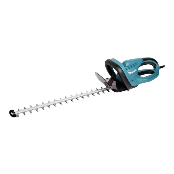
Makita UH6570 Technical Information
Hedge trimmers 650mm/ 550mm/ 450mm
Hide thumbs
Also See for UH6570:
- Instruction manual (33 pages) ,
- Parts list (3 pages) ,
- Catalog (13 pages)
Advertisement
Quick Links
T
ECHNICAL INFORMATION
Model No.
Description
C
ONCEPT AND MAIN APPLICATIONS
Models UH6570/UH5570/UH4570 for semiprofessional
applications have been developed as the successors to the
current UH6350/UH5550/UH4850/UH4050, featuring
renewed external appearance and more improved handling.
S
pecification
Voltage (V)
110
120
220
230
240
Specifications
Blade length: mm (")
No load speed: min-
North America
Tooth pitch
Other countries
Protection from electric shock
Power supply cord: m (ft)
Net weight: kg (lbs)
*1: spm= strokes per minute
*2: Kuwait: 2.5m (8.2ft)
S
tandard equipment
Blade cover .................................... 1
Hook complete ................................ 1
Cord holder complete set ................ 1
Extension cord (10m) ..................... 1 (for UK [240V] only)
Note: The standard equipment for the tool shown above may differ by country.
O
ptional accessories
Shear blade assembly set
Blade cover
Hook complete
Cord holder complete set
Arm band complete set
Chip receiver assembly set
UH6570/ UH5570/ UH4570
Hedge Trimmers 650mm/ 550mm/ 450mm
Current (A)
Cycle (Hz)
5.3
50/60
4.8
50/60
2.6
50/60
2.5
50/60
2.4
50/60
Model No.
UH6570
650
(25-1/2)
=spm*
1
1
3.7
(8.1)
Dimensions for North America: mm (")
UH6570
Model No.
Length (L)
1,136 (44-3/4)
Width (W)
Height (H)
Dimensions for other countries: mm (")
UH6570
Model No.
Length (L)
1,042 (41)
Width (W)
Height (H)
Continuous Rating (W)
Input
550
---
550
550
550
UH5570
UH4570
550
450
(21-5/8)
(17-3/4)
1,600
1/2"
28mm
Double insulation
0.3 (0.98)*
2
3.6
3.5
(7.9)
(7.7)
PRODUCT
W
L
UH5570
1,031 (40-1/2)
223 (8-3/4)
206 (8-1/8)
UH5570
UH4570
970 (38-1/4)
862 (34)
223 (8-3/4)
206 (8-1/8)
Max. Output (W)
Output
230
500
230
500
230
500
230
500
230
500
P 1/ 7
H
Advertisement

Related Manuals for Makita UH6570


Summary of Contents for Makita UH6570
- Page 1 UH6570/ UH5570/ UH4570 Description Hedge Trimmers 650mm/ 550mm/ 450mm ONCEPT AND MAIN APPLICATIONS Models UH6570/UH5570/UH4570 for semiprofessional applications have been developed as the successors to the current UH6350/UH5550/UH4850/UH4050, featuring Dimensions for North America: mm (") renewed external appearance and more improved handling.
-
Page 2: Necessary Repairing Tools
1R263 Bearing extractor Removing Gear housing cover [2] LUBRICATION Apply Makita grease N. No.2 to the following portion to protect parts and product from unusual abrasion. Refer to Fig. 5. 1) Gear room (6g: Refer to Fig. 5.) 2) Crank portion (a little: Refer to Fig. 4) 3) Shaft ends of Gear complete (a little: Refer to Fig. - Page 3 P 3/ 7 epair [3] DISASSEMBLY/ASSEMBLY [3] -1. Shear blade ass’y and Gear complete (cont.) ASSEMBLING Take the disassembling step in reverse. Note: Regarding the new Shear blade ass’y; - make sure that the routes for the two M5x25 Pan head screws are secured. - pass two M5x25 Pan head screws through the holes for Shear blade ass’y in advance.
- Page 4 P 4/ 7 epair [3] DISASSEMBLY/ASSEMBLY [3] -2. Motor, Switch and Power supply cord (cont.) ASSEMBLING Take the disassembling step in reverse. Note: 1) When setting Armature and Gear housing complete in place, pass Lever through Field at the same time while inserting the hinge portion of Lever into Housing L carefully because the hinge tends to remove.
- Page 5 P 5/ 7 epair [3] DISASSEMBLY/ASSEMBLY [3] -3. Lifter section DISASSEMBLING Refer to the clause of [3]-2. ASSEMBLING Refer to Fig. 14. Three plates X, Y and Z of Lifter have to be linked with each appropriate portion in the following order. 1.
-
Page 6: Circuit Diagram
P 6/ 7 epair [3] DISASSEMBLY/ASSEMBLY [3] -4. Switch lever B, Front grip and Protector DISASSEMBLING Fig. 15 Refer to Fig. 8. protrusion of tab of Switch Switch lever B lever B ASSEMBLING protrusion of Front grip 1) When separating Front grip from Switch lever B; - hook one end of Compression spring 9 with the protrusion of Front grip. -
Page 7: Wiring Diagram
P 7/ 7 iring diagram Fig. D-2 Connect Receptacles for Motor so that their lead wires face Housing L side. Insert Lead wires into the bottom of Lead wire holder here. Choke coil (if used) Terminal block Noise suppressor (if used)
Need help?
Do you have a question about the UH6570 and is the answer not in the manual?
Questions and answers