Acteon Xmind DC Installation & Maintenance Manual
Intraoral x-ray system at constant potential
Hide thumbs
Also See for Xmind DC:
- Installation & maintenance manual (80 pages) ,
- Installation & maintenance manual (51 pages)

Related Manuals for Acteon Xmind DC


Summary of Contents for Acteon Xmind DC
- Page 1 xmind ® intraoral x-ray system at constant potential INSTALLATION & MAINTENANCE MANUAL...
- Page 3 Control panel MAIN SWITCH CONTROL BUTTON DISPLAY X-RAY BUTTON RADIOGRAPHIC DISTANCE INDICATOR KEY TO DECREASE KEY TO INCREASE EXPOSURE TIME EXPOSURE TIME TUBEHEAD TYPE TUBEHEAD SELECTION INDICATOR SELECTION OF PATIENT RADIOGRAPHIC TYPE VOLTAGE INDICATOR SAVE IN MEMORY RADIOGRAPHIC MAXILLARY LOWER CURRENT INDICATOR TEETH MANDIBULARY LOWER...
- Page 4 THE RADIOGRAPHIC SYSTEM DESCRIBED IN THIS MANUAL REFERS TO A WALL INSTALLATION. ® “de Götzen S.r.l.” RESERVES THE RIGHT TO MODIFY THE DESIGN OF THIS PRODUCT AND THE MANUAL WITHOUT PRIOR NOTICE. COPIES, EVEN PARTIAL, OF THIS MANUAL ARE ALLOWED ONLY FOR IN-HOUSE USE.
-
Page 5: Table Of Contents
Summary Control panel .................... 3 CHAPTER 1 ....................4 PRELIMINARY INFORMATION ..................4 INFORMATION FOR THE INSTALLER ................. 4 CHAPTER 2 ....................5 RADIOGRAPHIC SYSTEM ....................5 SYSTEM COMPONENTS ....................5 OVERALL DIMENSIONS ....................5 IDENTIFICATION TAGS ....................8 CHAPTER 3 ....................9 INSTALLATION SPECIFICATIONS .................. -
Page 6: Chapter 1
CHAPTER 1 PRELIMINARY INFORMATION CHAPTER 1 PRELIMINARY INFORMATION ® Before you start to use the “xmind dc” radiographic system, it is recommended to carefully read and follow the instructions contained herein, in order to obtain the best possible performance. Always pay close attention to the CAUTION WARNING PLEASE NOTE... -
Page 7: Chapter 2
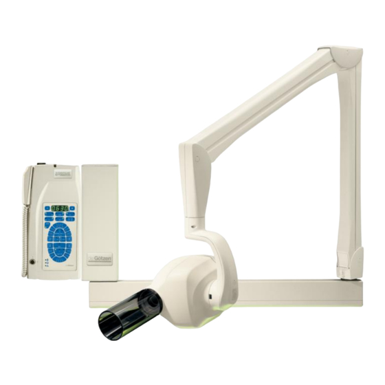
CHAPTER 2 RADIOGRAPHIC SYSTEM CHAPTER 2 RADIOGRAPHIC SYSTEM ® The “xmind dc” radiographic system (Figure 1) consist of: SYSTEM COMPONENTS ® 1. xmind TIMER 2. PANTOGRAPH ® 3. xmind dc TUBEHEAD 4. CONE 5. BRACKET 6. WALL PLATE Figure 1 OPTIONAL ... - Page 8 CHAPTER 2 OVERALL DIMENSIONS BRACKET 400 Figure 2A BRACKET 800 Figure 2B BRACKET 1100 Figure 2C Installation Manual ● X-Mind DC● W11000111 ● V1 ● (02) ● 07/2014 ● NXDCEN020A - Page 6 of 55...
- Page 9 CHAPTER 2 IDENTIFICATION TAGS Figures 3 and 4 show the typical dimensions of the radiographic system: Figure 3 Figure 4 Installation Manual ● X-Mind DC● W11000111 ● V1 ● (02) ● 07/2014 ● NXDCEN020A - Page 7 of 55...
-
Page 10: Identification Tags
CHAPTER 2 IDENTIFICATION TAGS IDENTIFICATION TAGS The identification tags on the tubehead, on the timer and on the cone indicate the model number, the serial number, the manufacturing date and the symbols of the main technical characteristics. TUBEHEAD ® de Götzen S.r.l. -
Page 11: Chapter 3
CHAPTER 3 INSTALLATION SPECIFICATIONS CHAPTER 3 INSTALLATION SPECIFICATIONS WARNING Prior to installing the radiographic system the Office Manager must ascertain that: the environment, the electric system and the power supply comply with the necessary requirements, otherwise he/she must make the necessary adjustment. ENVIRONMENTAL REQUIREMENTS ... - Page 12 CHAPTER 3 INSTALLATION SPECIFICATIONS REQUIREMENTS OF THE ELECTRIC LINE The electric line must be of the “single phase alternating” type. It is essential to fit a 16 A - 250 V, magnetothermal differential switch upstream to the radiographic system, with differential protection In 30 mA (refer to Chapter 15). ...
- Page 13 CHAPTER 3 INSTALLATION SPECIFICATIONS ELECTRIC CONNECTIONS WARNING Prior to installing the radiographic system, it is advisable that all the electric connections be arranged. TIMER On the timer installation wall, suitable runs for the following electric cables must be provided, according to the installation electric diagram (refer to Chapter 15): ...
-
Page 14: Chapter 4
CHAPTER 4 INSTALLATION CHAPTER 4 INSTALLATION CAUTION The “xmind dc” radiographic system must be installed by professionally trained technicians, who must be able to certify their work by “Declaration of Conformity”. WARNING Prior to installing the radiographic system, it is advisable to check that all necessary requirements have been met (refer to Chapter 3). -
Page 15: Assembling The Wall Plate
CHAPTER 4 ASSEMBLING THE WALL PLATE ASSEMBLING THE WALL PLATE WARNING When the timer is installed aside the wall plate, please do as follows: The timer must be mounted on the left side of the wall plate The distance between timer and wall plate must be 2.5 mm. WARNING To fix the wall plate DO NOT use plastic or rubber anchor screws. - Page 16 CHAPTER 4 ASSEMBLING THE WALL PLATE ASSEMBLY INSTRUCTIONS ( REFER TO IGURE 1. Remove the wall plate from the packaging and take out the drilling template . 2. Position the drilling template on the radiographic system installation wall, at the required height (130 cm from the base in the suggested height).
-
Page 17: Assembling The Bracket
CHAPTER 4 ASSEMBLING THE BRACKET ASSEMBLING THE BRACKET PLEASE NOTE The 82.5 cm and 110 cm brackets are provided with a stop key (Figures 7A and 7B) to prevent the electric cable from twisting. PLEASE NOTE Generally, the stop key is installed so that the equipment position at rest is on the right side of a possible watcher standing in front of the wall plate (Figure 7A). - Page 18 CHAPTER 4 ASSEMBLING THE PANTOGRAPH ASSEMBLY INSTRUCTIONS ( REFER TO IGURE 1. Take out the bracket from the packaging. 2. Insert the bracket pin into the wall plate (upwards). 3. Insert the supporting rest . Figure 8 PLEASE NOTE Prevent all foreign matters (ground, dust, cement, etc.
-
Page 19: Assembling The Pantograph
CHAPTER 4 ASSEMBLING THE PANTOGRAPH ASSEMBLING THE PANTOGRAPH ASSEMBLY INSTRUCTIONS ( REFER TO IGURE 1. Remove the pantograph from the packaging. 2. Remove the bracket plug by unscrewing the fixing screw . 3. Slide the bracket guard slat . 4. -
Page 20: Assembling The Timer
CHAPTER 4 ASSEMBLING THE TIMER ASSEMBLING THE TIMER CAUTION Check that the cable runs are arranged in the timer installation wall; check the compliance of the power supply with the installation specifications (refer to Chapter 3). WARNING Check that the rating data match the power supply voltage. WARNING When the timer is installed aside the wall plate, please do as follows: ... - Page 21 CHAPTER 4 ASSEMBLING THE TIMER ASSEMBLY INSTRUCTIONS ( 10-11) REFER TO IGURES 1. Remove the timer from the packaging and take out the drilling template . 2. Position the drilling template on the radiographic system installation wall, at the required height.
-
Page 22: Assembling The Tubehead
CHAPTER 4 ASSEMBLING THE TUBEHEAD ASSEMBLING THE TUBEHEAD ASSEMBLY INSTRUCTIONS 1. Take out the tubehead from the packaging. 2. Check that all the rating data matches the power supply voltage. 3. Remove both guards from the pantograph by loosening the relevant screws. -
Page 23: Balancing The Pantograph
CHAPTER 4 BALANCING THE PANTOGRAPH BALANCING THE PANTOGRAPH CAUTION The pantograph must only be adjusted when the tubehead is assembled. WARNING To prevent damage to the internal mechanism while performing adjustment and the balancing tests, the adjustment key must not be left in place. WARNING The adjustment key provided must be retained carefully. - Page 24 CHAPTER 4 BALANCING THE PANTOGRAPH INSTRUCTIONS ( REFER TO IGURE 1. BALANCING THE ARM A PLEASE NOTE The pantograph is supplied with arm A already preloaded. The arm B is supplied unloaded for safety reasons. 2. BALANCING THE ARM B Arm A vertical ...
- Page 25 CHAPTER 4 BALANCING THE PANTOGRAPH 5. Insert the movable finish F between the pantograph guard and metal frame. 6. Insert the pins of the guards into the relevant seats; then position them and check that the movable finish is coupled to the guards. Installation Manual ●...
-
Page 26: Chapter 5
CHAPTER 5 ELECTRIC CONNECTIONS CHAPTER 5 ELECTRIC CONNECTIONS CAUTION Before proceeding to connections, the power supply must be cut off. CAUTION For electric safety, it is essential that the ground conductors be correctly connected. WARNING While making connections, always respect the polarity PHASE/NEUTRAL. WARNING While stripping the cables, pay attention to the small copper wires that may fall on the printed circuit and cause short circuits or malfunctions. - Page 27 CHAPTER 5 ELECTRIC CONNECTIONS INSTRUCTIONS FOR CONNECTION TO THE FEEDING TERMINAL BOARD 1. Remove the terminal board cover by unscrewing the fixing screw . 2. Proceed to the electric connection as shown: IMPORTANT TERMINAL BOARD CONNECTION DIAGRAM BROWN L = PHASE ...
- Page 28 CHAPTER 5 ELECTRIC CONNECTIONS 3. Connect the pantograph cable shield to the grounding potential . 4. Connect the wall plate to the grounding potential . 5. Clamp the cables with the cable clamps provided. 6. Reassemble the terminal board cover. INSTRUCTION FOR CONNECTION TO THE TIMER 1.
- Page 29 CHAPTER 5 ELECTRIC CONNECTIONS 2 3A-3B 4A-AB 5 6 7 TUBEHEAD 1 CONTROL BUTTON TUBEHEAD 2 CONTROL BUTTON OPTIONAL TUBEHEAD 1 RX SIGNALLING LAMP OPTIONAL TUBEHEAD 2 RX SIGNALLING LAMP OPTIONAL RS232 COMMUNICATION FOR TUBEHEAD 1 RS232 COMMUNICATION FOR TUBEHEAD 2 TUBEHEAD 1 POWER SUPPLY TUBEHEAD 2 POWER SUPPLY...
-
Page 30: Chapter 6
CHAPTER 6 CONFIGURATION CHAPTER 6 CONFIGURATION ® The “xmind dc” radiographic system is factory configured in “standard mode”. On the control panel the LED relevant to the following exposure parameters will light up: No. of the selected tubehead LED 1 Supplied cone LED 8”... - Page 31 CHAPTER 6 CONFIGURATION The above configuration depends on the dip switch position on the timer electronics: ON = INSTALLED OFF = NOT INSTALLED IF THE LONG CONE IS USED 31 cm = 12” TUBEHEAD 1 TUBEHEAD DC TUBEHEAD 2 ...
-
Page 32: Changing The Configuration
CHAPTER 6 CHANGING THE CONFIGURATION CHANGING THE CONFIGURATION OSSIBLE MODIFICATIONS OF THE EXPOSURE VALUES Radiographic voltage (60 kV/70 kV) Radiographic current (4 mA/8 mA) Type of patient (ADULT/CHILD) Radiographic technique (refer to “User’s Manual” Chapter 4). OSSIBLE MODIFICATIONS OF THE EXPOSURE VALUES ... - Page 33 CHAPTER 6 CHANGING THE CONFIGURATION INSTRUCTIONS To change the selection of tubehead , activate the dip-switch no. 1 or the SWITCH dip-switch no. 3: If the tubehead is connected to the XRAY1 terminal board, put the dip-switch no. 1 in the ON position; otherwise in OFF position ...
-
Page 34: Chapter 7
CHAPTER 7 START UP CHAPTER 7 START UP CAUTION When all connections are completed, the installer must check the electric safety and functions of the system. INSTRUCTIONS Put the main switch located on the upper part of the timer in the “I” position (ON). -
Page 35: Chapter 8
CHAPTER 8 CHECKING THE INSTALLATION CHAPTER 8 CHECKING THE INSTALLATION STEP 1 CHECKING THE CONFIGURATION Check on the control panel that all LEDs corresponding to the required configuration are lit; otherwise, change them. STEP 2 CHECKING THE TIMER OPERATION 1. Check the correct operation of the control panel by selecting different exposure times. 2. - Page 36 CHAPTER 8 CHECKING THE EXPOSURE FACTORS STEP 5 CHECKING THE POWER ABSORBED BY THE RADIOGRAPHIC SYSTEM To check the power absorbed by the radiographic system a tester must be used, in the mode ammeter in AC: 1. Connect the instrument to the power supply line. 2.
-
Page 37: Checking The Exposure Factors
CHAPTER 8 CHECKING THE EXPOSURE FACTORS CHECKING THE EXPOSURE FACTORS STEP 1 CHECKING THE RADIOGRAPHIC VOLTAGE The radiographic voltage is measured using calibrated “non invasive” instrument. SET TECHNICAL FACTORS NOMINAL VOLTAGE 15% MAXIMUM VOLTAGE DROP NOMINAL HIGH VOLTAGE 60-70 kV NOMINAL CURRENT 4-8 mA SET EXPOSURE TIME... - Page 38 CHAPTER 8 CHECKING THE EXPOSURE FACTORS Dose in air is: SOURCE-SKIN DISTANCE 31 cm - 12” 20 cm = 8” 60 kVp - 4 mA = 2.2 mGy/s 30% 60 kVp - 4 mA = 4.5 mGy/s 30% 70 kVp - 4 mA = 3 mGy/s ...
-
Page 39: Chapter 9
CHAPTER 9 DIAGNOSIS CHAPTER 9 DIAGNOSIS ® With the “xmind dc” radiographic system it is possible to set and visualise certain functional parameters. To set the parameters, the installer must: Select the tubehead Turn off the timer Turn on the timer, by keeping the key pressed ... -
Page 40: Chapter 10
CHAPTER 10 CALIBRATION OF THE TUBEHEAD CHAPTER 10 CALIBRATION OF THE TUBEHEAD CAUTION During this operation there is x-ray output. It is mandatory to adopt all the safety measures relevant to radioprotection. INSTRUCTION 1. Turn off the timer. 2. Turn on the timer by keeping pressed the key. -
Page 41: Chapter 11
CHAPTER 11 ERROR MESSAGES CHAPTER 11 ERROR MESSAGES ® The following chart gives a list of error messages that may appear while the “xmind dc” radiographic system is working. The chart also includes the causes of the error messages and what to do to solve them. Installation Manual ●... - Page 42 CHAPTER 11 ERROR MESSAGES ERROR CAUSE SOLUTION MESSAGES RX1 TUBEHEAD IS NOT CONNECTED OR IS CALL THE “AFTER SALES SERVICE” OUT OF ORDER RX2 TUBEHEAD IS NOT CONNECTED OR IS CALL THE “AFTER SALES SERVICE” OUT OF ORDER CORRUPTED EEPROM DATA CALL THE “AFTER SALES SERVICE”...
-
Page 43: Chapter 12
CHAPTER 12 RECOMMENDED MAINTENANCE CHAPTER 12 RECOMMENDED MAINTENANCE In order to guarantee safety of the radiographic system, it is necessary to set up a maintenance schedule. The owner is responsible for organising and observing a maintenance schedule which must be executed by qualified technicians who must be able to certify their work with a “Conformity Declaration”. - Page 44 CHAPTER 12 CLEANING THE OUTER SURFACE INSTRUCTIONS 1. Cut off the power. 2. Release the spring of the arm B of the pantograph using the key provided. 3. Remove the tubehead. 4. Withdraw the wall plate guard. 5. Remove the terminal board cover and disconnect the pantograph cable. 6.
-
Page 45: Chapter 13
CHAPTER 13 REPLACEMENT OF FUSES CHAPTER 13 REPLACEMENT OF FUSES The timer electronic equipment is protected by no. 4 fuses located on the electronic circuit. To replace them proceed as follows: INSTRUCTIONS 1. Cut off the power supply. 2. Temporarily remove the guard of the timer by unscrewing the fixing screws . -
Page 46: Chapter 14
CHAPTER 14 REPAIRS CHAPTER 14 REPAIRS In case of a malfunction, send the defective part using the original packaging to: de Götzen S.r.l. Via Roma 45 21057 OLGIATE OLONA VA ITALY Tel. +39 0331 376760 r.a. Fax +39 0331 376763 E-mail: degotzen@degotzen.com DISPOSAL The use of the WEEE symbol... -
Page 47: Chapter 15
CHAPTER 15 ATTACHMENTS CHAPTER 15 ATTACHMENTS The manufacturer undertakes to supply, upon request, drawings, circuit diagrams, component parts lists, instructions or other information needed by qualified technical personnel to perform repairs ® on those parts of the “xmind dc” radiographic system which may be repaired. ®... - Page 48 CHAPTER 15 ATTACHMENTS ® SPARE PARTS xmind LIGHT (OPTIONAL) CODE RAL 9010 VERSION Q.TY PCS XG LIGHT (1) LOWER & UPPER SHELL 29700977 29700977.C XG LIGHT (2) LAMPSOCKET 33400372 33400372 XG LIGHT (3) LIGHT BULB 230V 15W 33300352 33300352 XG LIGHT (3) LIGHT BULB 115V 15W 33300390 33300390 XG LIGHT (4) BOARD 230V...
- Page 49 CHAPTER 15 ATTACHMENTS ® SPARE PARTS xmind ECB (OPTIONAL) CODE RAL 9010 VERSION Q.TY PCS XG ECB (1) LOWER & UPPER SHELL 29700978 29700978.C CONTROL BOARD WITH BUTTON AND LED 39700303 39700303 XG ECB (3) SWITCH WITH KEY 35100298 35100298 Installation Manual ●...
- Page 50 CHAPTER 15 ATTACHMENTS xmind ® SPARE PARTS TIMER xmind CODE RAL 9010 VERSION Q.TY PCS AC/DC XG TIMER (1) TEMPLATE 24200883 24200883 AC/DC XG TIMER (2) CONTROL BOARD 39200306 39200306 AC/DC XG TIMER (2) US CONTROL BOARD 39200307 39200307 AC/DC XG TIMER (3) XM COILED CORD 32000325 32000325.C AC/DC XG TIMER (4) XM DOUBLE COILED...
- Page 51 CHAPTER 15 ATTACHMENTS ® SPARE PARTS PANTOGRAPH TYPE ARM xmind CODE RAL 9010 VERSION Q.TY PCS AC XG B (1) CABLE + CONNECTOR 3 POLES 39700384 39700384 DC XG B (2) CABLE + CONNECTOR 5 POLES 39700381 39700381 AC/DC XG B (3) TUBEHEAD SIDE SHELLS 29700990 29700990.C FRONT PANTOGRAPH TYPE ARM ROD...
- Page 52 CHAPTER 15 ATTACHMENTS SPARE PARTS WALL PLATE 350 CODE RAL 9010 VERSION Q.TY PCS COVER (1) PLATE DEG 29700985 29700985.C COVER (1) PLATE SAT 29700986 29700986.C AC/DC XG B & HALF-MOON PLATE 22000176 22000176 PLATE (3) TEMPLATE 24200984 24200984 PLATE (4) INSERT + PLUGS 29701036 29701036.C WALL PLATE 350 DEG...
- Page 53 CHAPTER 15 ATTACHMENTS SPARE PARTS WALL PLATE 350 TOP CODE RAL 9010 VERSION Q.TY PCS COVER (1) PLATE DEG 29700985 29700985.C COVER (1) PLATE DEG 29700986 29700986.C AC/DC XG B & HALF-MOON PLATE 22000176 22000176 PLATE (3) TEMPLATE TOP MOUNT 24201002 24201002 PLATE (4) INSERT + PLUGS...
- Page 54 CHAPTER 15 ATTACHMENTS SPARE PARTS BRACKET CODE RAL 9010 VERSION Q.TY PCS BRACKET 400 29700380 29700380.C COMPLETE BRACKET 800 29700378 29700378.C COMPLETE BRACKET 1100 29700379 29700379.C COMPLETE SPARE PARTS BRACKET CODE RAL 9010 VERSION Q.TY PCS CEILING BRACKET 29700382 29700382.C COMPLETE SPARE PARTS BRACKET CODE...
- Page 55 CHAPTER 15 ATTACHMENTS Installation Manual ● X-Mind DC● W11000111 ● V1 ● (02) ● 07/2014 ● NXDCEN020A - Page 53 of 55...
Need help?
Do you have a question about the Xmind DC and is the answer not in the manual?
Questions and answers