Table of Contents
Advertisement
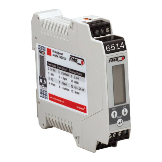
Digital Microprocessor Controlled Tension Amplifier
Digital Microprocessor Controlled Tension Amplifier
with intuitive operation via FMS ComACT
Firmware Version EMGZ310
Firmware Version EMGZ310.ComACT
This operation manual is also available in German.
Diese Bedienungsanleitung ist auch in Deutsch erhältlich.
Bitte kontaktieren Sie Ihren nächstgelegen FMS Vertreter.
© by FMS Force Measuring Systems AG, CH-8154 Oberglatt – All rights reserved.
Operating Manual
EMGZ310
EMGZ310.ComACT
Version 2.10
Please contact your local FMS representative.
10/2016 NS
V1.14
V2.10
app
TM
Advertisement
Table of Contents

Related Manuals for FMS EMGZ310


Summary of Contents for FMS EMGZ310
- Page 1 This operation manual is also available in German. Please contact your local FMS representative. Diese Bedienungsanleitung ist auch in Deutsch erhältlich. Bitte kontaktieren Sie Ihren nächstgelegen FMS Vertreter. © by FMS Force Measuring Systems AG, CH-8154 Oberglatt – All rights reserved.
-
Page 2: Table Of Contents
2.6 Wiring the Amplifier 2.7 Modify the wiring Configuring the Amplifier ............... 10 3.1 Power up the EMGZ 310 3.2 Operating the EMGZ310 over the Operating Panel 3.3 Operating Panel 3.4 Change the Device Mode 3.5 Offset Compensation 3.6 Calibration 3.7 Calibration Procedure in the Force Gauge Mode... -
Page 3: Safety Instructions
Operating Manual EMGZ 310 1 Safety Instructions All safety related regulations, local codes and instructions that appear in the manual or on equipment must be observed to ensure personal safety and to prevent damage to the equipment connected to it. If equipment is used in a manner not specified by the manufacturer, the protection provided by the equipment may be impaired. -
Page 4: List Of Safety Instructions
It is vital to ensure a proper earth ground connection Each change of the Device Mode requires a re-calibration of the system Changes or modifications made to this equipment not expressly approved by FMS AG may void the FCC authorization to operate this equipment. 28.06.2018... -
Page 5: Regulatory Notices
Operating Manual EMGZ 310 1.3 Regulatory Notices NOTE: This device complies with Part 15 of the FCC Rules and with Industry Canada licence-exempt RSS standard(s). Operation is subject to the following two conditions: • this device may not cause harmful interference, and •... -
Page 6: Notes Réglementaires
Operating Manual EMGZ310 and EMGZ310.ComACT NOTE: Changes or modifications made to this equipment not expressly approved by FMS Force Measuring Systems AG may void the FCC authorization to operate this equipment. Radiofrequency radiation exposure Information: This equipment complies with FCC and IC radiation exposure limits set forth for an uncontrolled environment. -
Page 7: Quick Installation Guide
Operating Manual EMGZ 310 2 Quick Installation Guide In a Plug & Play configuration the set-up of the EMGZ310 and force sensor is limited to only the offset compensation and the calibration. 2.1 Preparations for Set-up 1. Read the Operation Manual of your force measuring sensors 2. -
Page 8: Block Diagram
Operating Manual EMGZ310 and EMGZ310.ComACT 2.5 Block diagram Fig. 1: Block diagram EMGZ310 EMGZ310_BA_Manual.ai 2.6 Wiring the Amplifier One or two force sensors can be connected to the measuring amplifier. When using two force sensors, the output signal of the measuring amplifier will then correspond to the average value of the two sensors. -
Page 9: Modify The Wiring
Operating Manual EMGZ 310 Caution Bad earth connection may cause electric shock to persons, malfunction of the total system or damage of the control unit. It is vital to ensure a proper earth ground connection. Note The shield should be connected only to the electronic unit. On the force sensor side the shield should stay open. -
Page 10: Configuring The Amplifier
3 Configuring the Amplifier 3.1 Power up the EMGZ 310 1. Connect the first force sensor (see Fig.2 Wiring Diagram EMGZ310) 2. Check whether applying a force in measuring direction (in the direction of the red point) on the first sensor results in a positive output signal. If not, exchange the two signal wires of this force sensor in the terminal block (terminals 6/7). -
Page 11: Change The Device Mode
Operating Manual EMGZ 310 3.4 Change the Device Mode The EMGZ310 amplifier has two Device Modes: ● Display of Force Gauge: Tension data are displayed in a force unit ● Display of Voltage Gauge: Tension data are displayed in Volt (V) Output 1. -
Page 12: Calibration
C431011e because of space restrictions), the gain can be calculated with the FMS Calculator tool. This Calculator can be down loaded from the FMS web page. The calculated GAIN value can be entered in the configuration of the amplifier. 28.06.2018... -
Page 13: Calibration Procedure In The Force Gauge Mode
Operating Manual EMGZ 310 3.7 Calibration Procedure in the Force Gauge Mode Note If you do not press any key on the operating panel the display will automatically switch to the intitial screen. You have to repeat any previously performed steps. Execute the single steps uninterrupted and prepare any required material in advance. -
Page 14: Calibration Procedure In Volt Gauge Mode
Operating Manual EMGZ310 and EMGZ310.ComACT The display shows the unit of measure that was previously selected. Enter the force corresponding to your calibration weight Permanent key pressing expedites the changing speed. 3.8 Calibration Procedure in Volt Gauge Mode 1. Load a rope with a defined weight corresponding to your calibration force on the roller. -
Page 15: Configuration Via Operating Panel
Operating Manual EMGZ 310 4 Configuration via operating panel After having done the offset and calibration procedures the system is configured and ready for operation. Description of parameterization: 1. Press the key PARA for longer than 3 seconds, to enter the Output parameter-select mode. - Page 16 Operating Manual EMGZ310 and EMGZ310.ComACT In the Parameterisation State the EMGZ 310 can be brought into the 2 modes: “Parameter Selection” and “Parameter Change”. Fig. 6: State Diagram Parameter Setting (1 part) E310010e The display shows the unit of measure that was previously selected.
-
Page 17: Reset To Default Parameter Set
Operating Manual EMGZ 310 Fig. 7: State Diagram Parameter Setting (2 part) E310011e 4.1 Reset to Default Parameter Set Fig. 8: Reset to Default Parameter Set E310012e 28.06.2018... -
Page 18: Parameter List
Operating Manual EMGZ310 and EMGZ310.ComACT 4.2 Parameter List Parameter Unit Default Remarks Output [mA] 0...20 or 4...20 4…20 Current output Filter [Hz] 999.9 10.0 Noise filter Unit N; kN; g; kg; or lb System unit Sys_F N; kN; g; 100’000... -
Page 19: Description Of Parameters
Operating Manual EMGZ 310 4.3 Description of Parameters Current Output Selection LCD: .Output Use: This parameter selects the current output signal of the amplifier. The voltage output (+/-10V) is parallel in use Parameter Range Unit Selection Default 4..20mA 4..20mA 0..20mA Low-pass Filter LCD: Filter Use:... - Page 20 Operating Manual EMGZ310 and EMGZ310.ComACT Unit of Measure LCD: Unit Use: This parameter determines the unit used in the system The label on the force sensor shows always the nominal force in N. By changing the units to lb (pounds) the whole unit system will change from metric to imperial units.
- Page 21 Operating Manual EMGZ 310 Use: This parameter defines what force value (N, kN, lb, g, kg) corresponds to the maximum output of the amplifier (10V or 20mA). If the Device Mode Volt Gauge is set, this parameter is deactivated Parameter Range Unit Selection Default...
-
Page 22: Configuration Via Fms Comact
FMS ComACT app. You can identify the type of amp on the type label. The EMGZ310.ComACT has also the last 4 digits of its serial number printed on the front housing. -
Page 23: Screenshots
The procedures of offset compensation and calibration are always identical to an amplifier without Bluetooth connectivity. Instead of using the operating panel of the amplifier, you can use here any mobile device for input and configuration. Download FMS Overview with all Display of actual “Configure”... -
Page 24: Dimensions
Operating Manual EMGZ310 and EMGZ310.ComACT 6 Dimensions Fig. 8: Drawing EMGZ 310 rail mount housing E310004 28.06.2018... -
Page 25: Technical Specification
Operating Manual EMGZ 310 7 Technical Specification Amplifier type Digital, microprocessor controlled # of channel 1 channel for 2 sensors @ 350 Ω Sensor excitation 5VDC max. 30mA (high voltage stability) Linearity error < 0.1% Processor cycle time Operation / parameter setting 3 keys, 4-digit LCD display (alpha-num) Resolution A/D converter ±8192 digit (14 bit) -
Page 26: Your Settings
Operating Manual EMGZ310 and EMGZ310.ComACT 8 Your Settings Parameter Your Settings Remarks Output Current output Filter Noise filter Unit System unit Sys_F System force of the roller F@mOut Force at max. output Offset Roller weight Gain Amplification Mode Requires new calibration... -
Page 27: Notes
Operating Manual EMGZ 310 9 Notes 28.06.2018... - Page 28 Operating Manual EMGZ310 and EMGZ310.ComACT FMS Force Measuring Systems AG FMS Italy FMS USA, Inc. FMS UK Aspstrasse 6 Via Baranzate 67 2155 Stonington Ave. Suite 119 Highfield, Atch Lench Road 8154 Oberglatt (Switzerland) I-20026 Novate Milanese Hoffman Estates, IL 60169 USA Church Lench Tel.
Need help?
Do you have a question about the EMGZ310 and is the answer not in the manual?
Questions and answers