
Related Manuals for Clarke CEA150


Summary of Contents for Clarke CEA150
- Page 1 150MM ELECTRIC EARTH BORER MODEL NO: CEA150 PART NO: 3400997 OPERATING & MAINTENANCE INSTRUCTIONS GC0915...
-
Page 2: Environmental Recycling Policy
INTRODUCTION Thank you for purchasing this CLARKE Electric Earth Borer designed for boring holes in soil only, for fence posts, re-forestation, and similar operations. Before attempting to use this product, please read this manual thoroughly and follow the instructions carefully. In doing so you will ensure the safety of yourself and that of others around you, and you can look forward to your purchase giving you long and satisfactory service. -
Page 3: Specification
SPECIFICATION Model Number CEA150 Voltage 230 V @ 50 Hz Duty Cycle Continuous Output Speed 200 rpm Overload Clutch Torque 120 Nm Sound Pressure Level (L 90 dB(A) Guaranteed Sound Power (L 102 dB(A) Vibration 5.5m/s (K=1.5 m/s Dimensions with auger (L x W x H) - Page 4 13. Guard against electric shock. Prevent body contact with grounded surfaces. 14. Replacement parts and accessories. When servicing, your Clarke dealer will only use only identical replacement parts. Use of any other parts will void the warranty. Only use accessories intended for use with this tool.
-
Page 5: Electrical Connections
ELECTRICAL CONNECTIONS WARNING! Read these electrical safety instructions thoroughly before connecting the product to the mains supply. Before switching the product on, make sure that the voltage of your electricity supply is the same as that indicated on the rating plate. This product is designed to operate on 230VAC 50Hz. -
Page 6: Product Overview
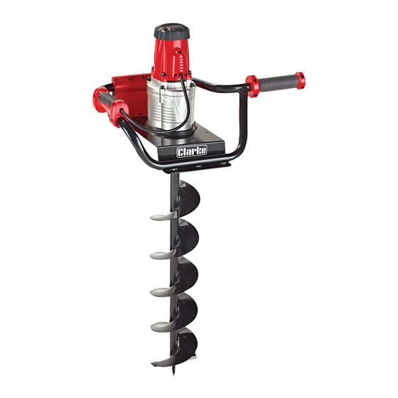
PRODUCT OVERVIEW DESCRIPTION DESCRIPTION Left Handle Power Cable Right Handle Power Plug Trigger Switch with Lock Auger Bit Parts & Service: 020 8988 7400 / E-mail: Parts@clarkeinternational.com or Service@clarkeinternational.com... -
Page 7: Operation
INSTALLING THE AUGER BIT 1. Slide the auger bit onto the drive shaft, insert the securing pin and secure with the split pin provided. 2. Plug the auger into a suitable mains power outlet via a suitable extension cable marked for outdoor use. -
Page 8: Maintenance
USING THE AUGER 1. Put the point of the auger at the location of the hole. 2. Depress the safety button and slowly squeeze the trigger to start the machine. • The auger bit will start rotating. 3. Apply a light downward pressure to drill the hole. -
Page 9: Parts List And Diagram
PARTS LIST AND DIAGRAM Parts & Service: 020 8988 7400 / E-mail: Parts@clarkeinternational.com or Service@clarkeinternational.com... - Page 10 DESCRIPTION PART NO DESCRIPTION PART NO Left Handle Half WGCEA15001 Gear Sleeve WGCEA15037 Supporting Frame WGCEA15002 Gear WGCEA15038 Right Handle Half WGCEA15003 Upper Flange Washer WGCEA15039 Screw WGCEA15004 Coil Spring WGCEA15040 Auger Bit WGCEA15005 Spring Flange Washer WGCEA15041 Bolt WGCEA15006 WGCEA15042 WGCEA15007 Gear Casing...
-
Page 11: Declaration Of Conformity
DECLARATION OF CONFORMITY Parts & Service: 020 8988 7400 / E-mail: Parts@clarkeinternational.com or Service@clarkeinternational.com...
Need help?
Do you have a question about the CEA150 and is the answer not in the manual?
Questions and answers