Advertisement
Wemos connections to the EMS board
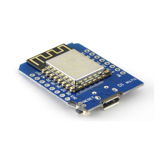
The Wemos D1 Mini versions all have the same pinout, however the text on the board may vary
slightly. Below two examples.
Wemos D1 Mini V3
RX
TX
VC
Pin EMS board
VC
TX
RX
GD
The Wemos, if purchased from me, comes pre-loaded with a stable firmware version from
https://github.com/proddy/EMS-ESP. I don't provide detailed support for the firmware itself as it is
not my own. Please READ the documentation on the repository very carefully.
When you power up the Wemos, it will start in Access Point (AP) mode. Connect via WiFi to the SSID
EMS-ESP and telnet to 192.168.4.1. (f.i.
set wifi
command to configure your own network settings like
wifi_password
.
Alternatively connect the ESP8266 to your PC and open a Serial monitor to configure the settings.
Make sure you disable Serial support before connecting the EMS lines using
Play around in the Telnet session with the available settings to make sure the Wemos can read and
write correctly to the EMS bus. The next step is integrating it into your home automation system. For
Home Assistant there is a full set of YAML configuration files available and for Domoticz there is a
first version of a python plugin available. You can find both in the
For Domoticz you also need to install a MQTT server/broker like Mosquitto.
If you don't know what this all means, please Google around and check the HA or Domoticz forum for
support on this.
It's also a good idea to give the Wemos a fixed IP address (also called a DHCP reservation) so your
home automation system can always find the Wemos even after reboots etc. You need to set this in
your router.
Take special care when upgrading the firmware on the Wemos. Read the complete Readme file on the
repository so you know exactly what you are doing otherwise you may brick the ESP!
Wemos pin
3V3
(NOT 5V!!)
D8
D7
G or GND
Putty
Wemos D1 Mini V2
RX
TX
VC
GD
After you connected the 4 wires as instructed
above, you can plugin a USB cable to the
Wemos to power it all up.
is a simple program to use Telnet with). Then use the
set set wifi_ssid
'doc' folder of the
GD
and
set
set serial off
.
repository.
Advertisement
Table of Contents

Related Manuals for Wemos D1 Mini V3

Summary of Contents for Wemos D1 Mini V3
- Page 1 I don’t provide detailed support for the firmware itself as it is not my own. Please READ the documentation on the repository very carefully. When you power up the Wemos, it will start in Access Point (AP) mode. Connect via WiFi to the SSID EMS-ESP and telnet to 192.168.4.1. (f.i.
- Page 2 EMS bus interface board manual Current board version: 0.9 - April 2018 – Last document update 11 April 2019. Please see the Github repository for all the details about working with the EMS bus. https://github.com/bbqkees/Nefit-Buderus-EMS-bus-Arduino-Domoticz Connectors on the board Number J# Header function Remark EMS screw terminal...
- Page 3 Important note: The board can be powered with either 5V or 3.3V. However, this is also the voltage for the signal level on the UART. If you use 5V to power the board, 5V will also be your UART signal level and this will potentially destroy f.i.
- Page 4 Connecting to the bus You can use EITHER the EMS bus service jack OR the screw terminal. Do not connect them at the same time, because you might short circuit the bus. If you use the screw terminal, polarity does not matter because the circuit corrects both orientations. You can use the following Github repository as a general starting point: https://github.com/bbqkees/EMS-Wiki...
Need help?
Do you have a question about the D1 Mini V3 and is the answer not in the manual?
Questions and answers