Table of Contents
Advertisement
Quick Links
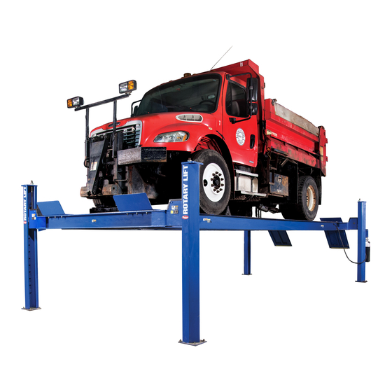
SM30 Capacity 30,000 lbs. (15,000 lbs. per axle)
RFL25 Capacity 25,000 lbs. (12,500 lbs. per axle)
© July 2018 by Vehicle Service Group.
SM30/RFL25
140" Minimum Wheelbase
CO10598.0
LP20460
I
I
N
N
S
S
T
T
A
A
L
L
L
L
A
A
T
T
I
I
O
O
N
N
I
I
N
N
S
S
T
T
R
R
U
U
C
C
T
T
I
I
O
O
N
N
S
S
IN20490
Rev. J 7/24/2018
Advertisement
Table of Contents

Related Manuals for Rotary SM30


Summary of Contents for Rotary SM30
- Page 1 SM30/RFL25 SM30 Capacity 30,000 lbs. (15,000 lbs. per axle) 140” Minimum Wheelbase RFL25 Capacity 25,000 lbs. (12,500 lbs. per axle) IN20490 LP20460 © July 2018 by Vehicle Service Group. CO10598.0 Rev. J 7/24/2018...
- Page 2 Obstruction Right Runway Front Clearance Rear Clearance Rear Clearance (Min. 5'-6" for SM30's, 8'-6" for Front Clearance = front overhang of RFL25's) = rear overhang of longest vehicle + required longest vehicle + required work space work space Fig. 1 Read and understand Installation Instructions completely 2.
- Page 3 Cable Seating in Sheave Grooves Right Rear Left Rear Cable (#4) Cable (#3) Right Front Left Front Cable (#2) Right Rear Cable (#1) Left Rear Cable (#4) Cable (#3) Rear Front (Viewed from front) (Viewed from rear) Fig. 3 Feed Cable Ends Through Yoke End E.
- Page 4 5. Columns: IMPORTANT The yoke/column alignment studs MUST be used Note: Columns are not interchangeable. They must be set at their for proper centering of columns to yokes, Fig. 8. A gap of respective corner of the lift. Column double return bend is always ”...
- Page 5 Check Lift Dimensions Double Return Bend always to the Inside of Lift. RFL25 ..177 1/8" Ref. SM30S ..249 1/8" Ref. SM30L ..285 1/8" Ref. SM30E L ..321 1/8" Ref. Power Unit Column Between Columns Width and length measurements are made from column sides, NOT column base plate.
- Page 6 6. Concrete and Anchoring: Drill holes using 5/8” car- Clean hole. Run nut down just Tighten nut with bide tipped masonry drill below impact section Torque wrench to bit per ANSI B212.15-1994 of bolt. Drive anchor 60 ft.-lbs (R2000) into hole until nut and washer contact base.
- Page 7 A. Keep columns square to center line of lift. Check lift location in the bay, Fig. 1. Check dimensions side-to-side, front-to- Shimming Column rear, and diagonally. Diagonals must be equal to within ”, Fig. 9. for each column. B. Start with power unit column. Use yoke spacer tool to ensure ”...
- Page 8 8. Adjust Cable: 9. Power Unit: Adjust all cables with lift fully lowered. Loosen cable jam nut. A. Align Air Valve Bracket with holes in right side of column bracket, Fig. 16. Tighten adjusting nut on cable stud on top of column until yoke end is raised ”.
- Page 9 Mount Power Unit Place air valve bracket on column bracket On one bolt, place before attaching motor. (2) 5/16" Star Washers Push nuts hold Use (4) 5/16"-18NC X 1 1/2" lg. bolts to brackets. HHCS and Nuts. PUSH TO RELEASE LATCHES NP280 Fig.
- Page 10 Note: Motors utilizing 3 phase current available. Refer to wiring NEED drawing in 3 phase power unit carton. IMPORTANT Use separate circuit for each power unit. ASSISTANCE? Protect each circuit with time delay fuse or circuit breaker: single phase -30 amp.; 3 phase (230v) -15 amp.; 3 phase (460v ) -8.75 amp, Fig.
- Page 11 Three Phase Power Unit MOTOR OPERATING DATA TABLE - THREE PHASE LINE VOLTAGE RUNNING MOTOR VOLTAGE RANGE 208-240V 50/60Hz. 197-253V 400V 50Hz. 360-440V 440-480V 50/60Hz. 396V-528V 575V 60Hz. 518V-632V Current Pin Layouts Older Pin Layouts 440-480V 50/60 Hz. 3Ø 575V 60 Hz. 3Ø 440-480V 50/60 Hz.
- Page 12 11. Fluid Filling: Seating Air Line CAUTION If fill/breather cap, Fig. 17, is lost or broken, order Tubing replacement. DO NOT substitute with a solid plug. A. System capacity is twenty-two (22) quarts. Use Dexron III Air Line ATF. Remove fill/breather cap and fill vent screw, Fig. 17. Tubing B.
- Page 13 13. Bleeding: Raise and lower lift (6) times. The cylinder is self- bleeding. After bleeding system, replace fill vent screw. Connect Air Supply to Air Valve Air Supply Note: Some fluid may be exhausted from the cylinder breather Filter vent during bleeding of the system. 14.
- Page 14 NOTES:...
- Page 15 NOTES:...
- Page 16 Please return this booklet to literature package, and give to lift owner/operator. Thank You Trained Operators and Regular Maintenance Ensures Satisfactory Performance of Your Rotary Lift. Contact Your Nearest Authorized Rotary Parts Distributor for Genuine Rotary Replacement Parts. See Literature Package for Parts Breakdown.
Need help?
Do you have a question about the SM30 and is the answer not in the manual?
Questions and answers