Table of Contents
Advertisement
Quick Links
Advertisement
Table of Contents

Related Manuals for PSC Solar SGS Series

Summary of Contents for PSC Solar SGS Series
- Page 1 Thank you for purchasing our products Please strictly comply with all warning notes and operating instructions in this manual. Keep this manual properly for future use. Please don’t operate Inverter until you carefully read all the safety and operating instructions.
- Page 2 Safe declare Operation safety 1. In the use of the product before, please read “safety declare”, to ensure the correct and safe to use. And please keep the manual. 2. Pay attention to the all warning when operating, according to the requirements for operation. 3.
-
Page 3: Table Of Contents
Index Chapter Ⅰ Product Introduction......................1-4 1.1 Synopsis...................................1 1.2 Topology.................................1 1.3 Operational principle............................1-2 1.4 Structure configuration............................2-3 1.5 Specification................................4 Chapter Ⅱ Installation..........................5-8 2.1 Environmental requirements...........................5 2.2 Unpacking................................5 2.3 Mechanical size..............................5-6 2.4 Transport................................6-7 2.5 Method of fix................................7 2.6 Terminal block connect............................8 Chapter Ⅲ Wiring..........................9- 3.1 Cable diameter choosing............................9 3.2 Cable connection..............................10-13 Chapter Ⅳ... -
Page 4: Chapter Ⅰ Product Introduction
Chapter Ⅰ Product Introduction 1.1 Synopsis SGS inverter is on/off grid with intelligent energy management, which transfers PV energy to gird or load. With built-in transformer and advanced DSP-based digital control technology, SGS inverter has high reliability,high efficiency, isolated stable output, abundant intelligent interfaces and supports any kinds of load. 1.2 Topology It consists of inverter (DC/AC), STS,built-in MPPT charger,isolated transformer and maintenance switch Q3, input switch Q1, bypass switch Q2 and output switch Q4. -
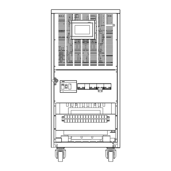
Page 5: Structure Configuration
Battery is charged by external solar charger. If the grid power is available, DC/AC inverter will feed the energy to the grid.If the grid power is abnormal, DC/AC inverter will power the load with off-grid function. If the battery voltage is extremely low, DC/AC will work as a charger to charge the battery. This DC/AC inverter is based on SPWM/SVPWM control technology with built-in transformer. - Page 6 Figure 1-5 Left view of 10-30kVA Figure 1-6 Right view of 10-30kVA...
-
Page 7: Specification
1.5 Specification Technical parameters Index Rated capacity 10kVA 20kVA 30kVA 20kW 30kW Rated output power 10kW MPPT Working Voltage and Actual battery voltage ~ DC480V(375V PV input voltage is Range recommended) Rated Power 10kw 20kw 30kw DC275V Floating Charge Voltage Solar Input 290V Boost charge Voltage... -
Page 8: Chapter Ⅱ Installation
Chapter Ⅱ Installation 2.1 Environmental requirements ■ Operating Temperature: 0~40℃ ■ Storage temperature: -15℃~45℃ ■ Relative Humidity: 20%~95% ■ Cooling Mode: Forced air cooling ■ Altitude: <1000m ■ Verticality: No vibration and the slope should be less than 5° ■ Pollution Level: Grade Ⅱ... -
Page 9: Transport
Figure 2-1 inverter power supply dimensions 2.4 Transport Lifting Transport 【Preparation】Two at least 3 meters long, bearing at least 1.5 tons of the cables. 【Transportation】The Inverter power supply cabinet should transport to the installation site before removing the packages, Lifting the two suspension ropes from the bottom. Figure 2-2 Illustration of lifting... -
Page 10: Method Of Fix
Figure 2-3 Unpacking Forklift Transport The equipment could be transported by forklift too. Beware that the Inverter is heavy and take care. Figure 2-4 Truck crossed the side 2.5 Method of fix Inverter passes its weight to the ground through four wheels. Use some auxiliary equipment to increase the contact area if the floor cannot withstand such pressure. -
Page 11: Terminal Block Connect
Terminal block of the Inverter locates at the front panel with a cover plate for protection. The indications of wiring are listed in Figure 2-5. BYPASS INPUT OUTPUT BATTERY SOLAR Figure 2-5 Terminal block of 10-30kVA... -
Page 12: Chapter Ⅲ Wiring
Chapter Ⅲ Wiring 3.1 Cable diameter choosing 3.1.1 Current carrying capacity of cable Table 3-1 shows the relation between cross-section area and current for safe operation. Current (A) Cross-section area (mm sectional area (mm rubber 25℃ plastic rubber 35℃ plastic 3-1 Wire sectional area - current 3.1.2 Selection of power cables Wires for mains input, bypass input, output, PE and battery need to be power cables. -
Page 13: Cable Connection
3.2 Cable connection 3.2.1 Power Cable Mains input and bypass input shares the same input in our factory to support single AC input. Figure 3-1, indicates that the customer does not have to connect bypass. If customer wants to operate the Inverter with dual AC input, remove the power cable between mains input and bypass first in the terminal block, then connect mains input and bypass input independently. - Page 14 Figure 3-2 10kVA Inverter Schematic diagram of the interface 1.Modbus card 2. RS232 Note: RS232 and SNMP cannot be used at the same time. RS232 connection RS232 communication line is included in the attachment. Connect it between Inverter and supervision terminal. The definition of each pin is shown in Figure 3-6.
- Page 15 UPS FAULT ALARM REM OTE SHUTDOWN COM M ON 1.6k B YPASS ON LOW BATTERY UPS ON INPUT M AINS FAULT REM OTE START 1.6K This interface provides only a circuit of “On” state (Low impedance) and “Off” state (High impedance), so external power supply may need for appropriate operation.
- Page 16 Function Description: Phenomenon Description Reason PIN1、PIN5 shorted FAULT Inverter internal fault 1.Battery mode PIN2、PIN5 shorted ALARM 2.Low battery 3.Inverter internal fault or alarm PIN3 GND OF INPUT PIN4 REMOTE SHUTDOWN External input signal, high active, remote shutdown PIN5 COMMON OF OUTPUT PIN6、PIN5 shorted BYPASS ON Inverter in bypass mode...
-
Page 17: Chapter Ⅳ Power On And Debugging
Chapter Ⅳ Power On and Debugging 4.1 Preparation 4.1.1 Input breaker description Bypass breaker Q2--- Switch on/off bypass AC, to the bypass STS Maintenance breaker Q3--- Switch on/off connection between bypass and output Output breaker Q4--- Switch on/off inverter output Battery breaker B1—Switch on the battery bank. - Page 18 Figure 4-1 Display Control Panel Analog fault condition (closing the input mains) to make an alarm, Check the "sound and light alarm" function, select "Menu" to enter to check the real-time display of inverter information.
-
Page 19: Chapter Ⅴ Lcd Panel Operation
Chapter Ⅴ LCD panel operation 5.1 LCD panel 5.1.1 Description Description of LCD panel is shown in Figure 5-1. 1. Maintenance bypass breaker status 2. Bypass breaker status 3. PV input breaker status 4. PV charger status 5. Inverter Status 6. - Page 20 5.1.2 HOME page description Some common inverter work situation will be described blow. 【Bypass mode】: Bypass mode flow figure as show in Figure 5-1-1-2. Figure 5-1-1-2 Bypass mode flow figure 【On grid mode】: On grid mode flow figure as show in Figure 5-1-1-3 Figure 5-1-1-3 On grid mode flow figure The flow figure of other work mode will not describe here.
-
Page 21: Display Information Details
information. 【Event Log】: Record the warning and faults during Inverter working time. 【System Setup】: Set the Inverter optional parameters, such as output voltage/frequency, battery number/charging current and others parameters 【About me】: Provide the Inverter manufacturers service hot line, fax, and email address. 5.1.4 Alarm buzzer 【Beep continuously】: Internal fault 【1 sound per 1second】: inverter overload warning, low battery and battery overcharge... - Page 22 Figure 5-4 System state Display 【Rated Information】Rated Information page consists of the information of machine mode, rated capacity, input, rated output and battery voltage. Figure 5-5 Rating Display 【Fault Record】: The event log records the warnings and failures according the time sequence. View the records by pressing Page UP/Page Down.
- Page 23 Figure 5-6 Event Record Display Figure 5-7 Delete event records to determine the display 【System Setup】: There are function setup and assistant setup in the system setup page. It’s shown in Figure 5-8. Figure 5-8 System Setup...
-
Page 24: System Control
5.3 System control 5.3.1 Turn on Inverter Press “INV.ON” icon to start inverter, LCD will display “Inverter is starting”. The working flow chart will be updated if Inverter is successfully started. It takes 20s to start the inverter. 5.3.2 Turn off Inverter Similarly, Press “INV.OFF”... - Page 25 3.【Load Information】There are battery voltage and current in battery status. It’s shown in Figure 5-4-3. Figure 5-4-3 Battery status 4.【Work Status】There are work mode solar/utility/output accumulation power in ACC power. It’s shown in Figure 5-4-4. Figure 5-4-4 ACC power 5.【Work Status】There are history accumulation power and today accumulation in solar energy. It’s shown in Figure 5-4-5.
-
Page 26: System Setup
Figure 5-4-5 Solar energy Figure 5-4-6 History year ACC energy 5.5 System setup There are function setup and assistant in system setup page. 5.5.1 Function setup There is Output voltage setup, voltage trimming, on gird, AC charge, Battery setup, Warranty setup, Parallel setup in function setup page. - Page 27 Figure 5-5-1-1 function settings 1.【Output setup】 200V, 208V, 220V, 230V, 240V (phase voltage) are available for Voltage setup; 50Hz/ 60Hz are available for frequency setup. It’s shown in Figure 5-5-1-2. Figure 5-5-1-2 Output setup 2.【Voltage trimming】Volt trimming can be accessed only by qualified person. The battery voltage could be adjusted.
- Page 28 Figure 5-5-1-3 Voltage trimming 3.【On grid】On grid parameter can be accessed only by qualified person. The on grid parameters could be set in this page. It’s shown in Figure 5-5-1-4. Figure 5-5-1-4 On grid setup 4.【Battery setup】Battery parameters can be accessed only by qualified person. It’s shown in Figure 5-5-1-5.
- Page 29 Figure 5-5-1-5 Battery setup 5.【AC charge】AC charge parameters can be accessed only by qualified person. It’s shown in Figure 5-5-1-6. Figure 5-5-1-6 AC charge setup 6.【Parallel setup】Parallel parameters can be accessed only by qualified person. It include parallel or single choose and Inverter address setup.
- Page 30 Figure 5-5-1-7 Parallel setup 5.5.2 Assistant Setup There are Buzzer setup Clear fault in Assistant Setup page. It’s shown in Figure 5-5-2-1. Figure 5-5-2-1 Assistant setup 1.【Clear Fault】If some not important appears fault, push this key can clear fault. 2.【Buzzer setup】Buzzer can enable or disable control in this page. It’s shown in Figure5-5-2-2.
-
Page 31: Inverter Alarm And Display
Figure 5-5-2-2 Buzzer setup 5.6 Inverter alarm and display When Inverter is abnormal or faulty, it will show the related sound and light alarm, and the fault record will be automatically saved for uses to review. Fault directions Fault reason Sound alarm Solution LCD display alarm... - Page 32 Fault directions Fault reason Sound alarm Solution Internal fault. Please contact with your LCD display alarm failure SCI fault Beep agency 1 sound per 2 Please check whether the fan is blocked Fan abnormal seconds or burned. 1 sound per 2 Internal fault.
-
Page 33: Chapter Ⅵ Operate And Maintenance Guide
Chapter Ⅵ Operate and maintenance guide This chapter describes Inverter normal operation and routine maintenance. Switch off solar breaker P1, bypass breaker Q2, battery breaker B1 and wait for 5 minutes to discharge the internal capacitors to safe voltage. Do not touch any internal components of Inverter before your reading of the operation guidelines and safety rules. -
Page 34: Maintenance Guide
6.2 Maintenance Guide 6.2.1 Routine maintenance Inverter is an intelligent system that needs little maintenance. However, we recommend you to do the inspections below to prolong Inverter’ life and improve its performance. 1. Daily inspection 1) Check the control panel: ICON indication, the LCD screen and buzzer; 2) Check the fan works or not;... -
Page 35: Chapter Ⅶ Fault Diagnosis
Chapter Ⅶ Fault diagnosis 7.1 Fault diagnosis procedure 【Status record】Record the LCD display content, buzzer sound, ICON indications and status of input breaker when Inverter fault occurs. 【Fault type identification】Refer to the fault table to confirm fault type. If the fault is not mentioned in the table, contact your vendor or technical support engineer for further information. -
Page 36: Appendix Ⅰ Start And Shutdown Inverter Operation Process
2. The red fault light in the front panel is not expected to be lighted if the Inverter is in normal situation. Contact your agency or our service department for further information. PSC Solar UK Physical Office/Warehouse: 41B, Olutoye Cres/Adeniyi Jones, Ikeja, Lagos State, Nigeria.
Need help?
Do you have a question about the SGS Series and is the answer not in the manual?
Questions and answers