Advertisement
Advertisement
Table of Contents

Subscribe to Our Youtube Channel
Related Manuals for Powercraft BD 501


Summary of Contents for Powercraft BD 501
- Page 1 Artikel-Nr.: 425052 Drill Press Ident-Nr.: 01011...
- Page 2 Komponenten / Ersatzteile Position Artikel-Nr. Beschreibung 425052001001 chuck 425052001002 Schaft 425052001010 Vierkantaufnahme 425052001052 table holder...
- Page 3 Operating Instructions Pillar Drill BD 501 Art.-Nr.: 42.505.23; I-Nr.: 01011...
- Page 4 Please fold out page 2 - 5.
- Page 7 Spindle Motor Pos. U/Min. Pos. U/Min. Pos. U/Min. Pos. tr/min Pos. tr/min Pos. tr/min Pos. t/min. Pos. t/min. Pos. t/min. Pos. r.p.m. Pos. r.p.m. Pos. r.p.m. Pos. o/min. Pos. o/min. Pos. o/min. 1550 1700 2350...
-
Page 8: Items Supplied
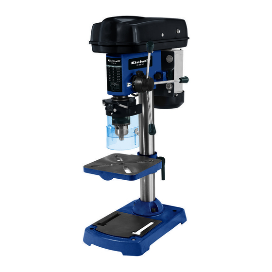
1.0. Layout (Fig. 1/2) Ensure proper voltage The voltage must comply with the specifications on 1. Machine base the rating plate. 2. Pillar 3. Fixing screw Use a socket-outlet with earthing contact 4. Drill table The device may only be operated from an outlet with 5. -
Page 9: Technical Data
Watch out for other persons Now, please read and follow all steps and procedures included in the operating Watch out for other persons (especially children) instructions. when using the device, and keep them away from your work area. Do not let anyone touch the device 5.0. -
Page 10: Operation
Note: All bare parts are greased in order to protect 7.0. Operation them from corrosion. Before mounting the drill chuck (10) onto the spindle (11), both parts must be Wear suitable, protective clothing (i.e. completely degreased using an environmentally rugged and tight-fitting) when working friendly solvent. - Page 11 7.4. Setting the speed (Fig. 1/5/6) 7.7. Setting the height of the drill table (Fig. 1) First switch the machine off, then pull out the mains Slacken the tightening screw (5). plug. Set the drill table (4) to the desired height by The various spindle speeds can be set by moving the pressing down or lifting up and simultaneously V-belt.
-
Page 12: Ordering Replacement Parts
9.0. Ordering replacement parts Drill bit Ø Cast iron Steel Iron Aluminium Bronze 2550 1600 2230 9500 8000 Replacement parts can be ordered through ISC 1900 1200 1680 7200 6000 GmbH (see the warranty declaration for the 1530 1340 5700 4800 address). - Page 13 Expolsion Diagram BD 501 Art.-Nr.: 42.505.23 I.-Nr.: 01011 42.505.21.02 42.505.21.03 42.505.21.04 42.505.21.01 42.505.21.05 o. Abb. Keilriemensatz 2-tlg. 42.505.21.07 o. Abb. Montagebeutel incl. Griffe 42.505.21.08...
- Page 15 Notes:...
- Page 16 Notes:...
- Page 17 Notes:...
-
Page 18: Warranty Certificate
WARRANTY CERTIFICATE The guarantee period begins on the date of sale and is valid for 2 years. Responsibility is assumed for faulty construction or material or functional defects. Any necessary replacement parts and necessary repair work are free of charge. We do not assume responsibility for consequential damage.
Need help?
Do you have a question about the BD 501 and is the answer not in the manual?
Questions and answers