
Related Manuals for ABB UCL


Summary of Contents for ABB UCL
- Page 1 1ZSC000562-AAZ en On-load tap-changers, type UCL and VUCL Installation and commissioning guide...
- Page 2 Any specific application not covered should be referred directly to ABB or its authorized representative. ABB makes no warranty or representation and assumes no liability for the accuracy of the information in this document or for the use of such information. All information in this document is subject to change without notice.
- Page 3 Used tap-changer oil from diverter switch housings and selector switch housings contains harmful Do not alter or modify a unit without first consulting ABB. substances. Fumes are irritating to the respiratory organs and the eyes and are highly flammable. Used Follow local and international wiring regulations at all times.
- Page 4 WARNING CAUTION Before carrying out work on the tap-changer, put To avoid seizing, do not operate the tap-changer the LOCAL/REMOTE switch on the motor-drive during the drying process or afterwards until it is filled mechanism to position 0. It is also advisable to shut with oil.
- Page 5 During service WARNING Small amounts of explosive gases may be emitted from the breathing devices (dehydrating breather or one-way breather). Make sure that no open fires, hot surfaces or sparks occur in the immediate vicinity of the breathing devices. WARNING If a power supply failure occurs during operation, the operation will be completed when the power returns.
-
Page 6: Table Of Contents
2.3 Temporary storage before assembly................14 3. Installation in the transformer ....................15 3.1 Cover-mounting ......................16 3.1.1 UCL/VUCL with tap selector size III ................16 3.2 Yoke-mounting ......................19 3.2.1 Mounting when the transformer ratio measurement is carried out before drying ..20 3.2.2 Mounting when the transformer ratio measurement is carried out after drying ..22 3.2.3 Mounting on transformer cover (after the drying process) ........23... - Page 7 6. Oil filling and draining ......................42 6.1 Filling methods and restrictions ..................42 6.2 Before filling ........................42 6.3 Filling at atmospheric pressure ..................42 6.4 Filling under vacuum .....................42 6.4.1 Oil conservator filled under vacuum ................42 7. Electrical connection and testing ..................44 7.1 General .........................44 7.2 Connecting and testing the motor-drive mechanism and the tap-changer ......44 7.3 Electrical tests on the transformer .................44...
-
Page 9: Introduction
Chapter 3. Horizontal drive shaft and protective tubes Oil valve Bevel gear Pressure relay Vertical drive shaft and protective tubes Motor-drive mechanism Fig. 1. On-load tap-changer system (single-unit shown). 1ZSC000562-AAZ en | Installation and commissioning guide UCL/VUCL 9... - Page 10 Not used for selector, size C Unit -1 Type of connection, B Unit -1 Unit -2 Type of connection, T Unit -1 Unit -2 Unit -3 Fig. 2. Example of on-load tap-changer systems. 10 Installation and commissioning guide UCL/VUCL | 1ZSC000562-AAZ en...
-
Page 11: Type Designation
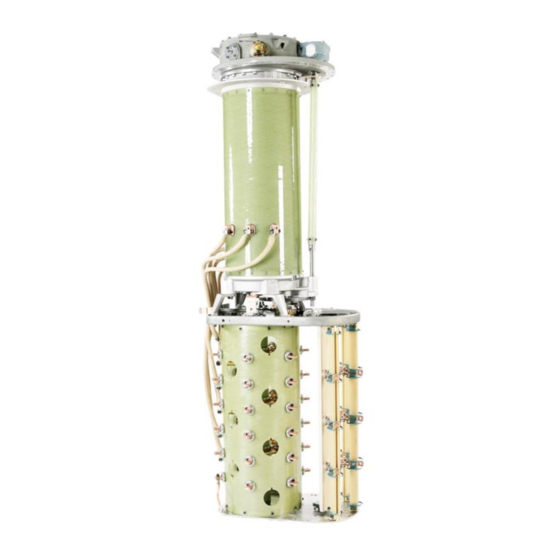
Serial no. B Three-phase delta (two units; single-phase and two-phase) Impulse withstand voltage to ground Maximum rated through-current Tap selector size Fig. 3. Diverter switch housing UCL/VUCL and tap selector III. 1ZSC000562-AAZ en | Installation and commissioning guide UCL/VUCL 11... -
Page 12: Required Tools
The conservator should also be equipped with an oil ABB). level indicator, and an alarm contact for low oil level is recommended. 12 Installation and commissioning guide UCL/VUCL | 1ZSC000562-AAZ en... -
Page 13: Oil Filter Unit For Continuous Oil Filtration
UCL.E 380/600, 900 380/1800 380/2400 650/600, 900 650/1800 650/2400 1050/600, 900 1050/1800 1050/2400 Table 2. Weights for type UCL. 1) The weight of the diverter switch, approximately 120 kg, is included. 1ZSC000562-AAZ en | Installation and commissioning guide UCL/VUCL 13... -
Page 14: Receiving
Keep the units in their plastic enclosures and do not remove the drying agent until assembly. 14 Installation and commissioning guide UCL/VUCL | 1ZSC000562-AAZ en... -
Page 15: Installation In The Transformer
Lowering the complete tap-changer to the floor without support entails a risk for tipping, personal injury and equipment damage. Tap selector Fig. 4. How to lift the diverter switch housing and the tap selector. 1ZSC000562-AAZ en | Installation and commissioning guide UCL/VUCL 15... -
Page 16: Cover-Mounting
Stud (x24) the tie-in resistor. It must be suspended from an overhead crane, for example. Gasket Transformer top cover Fig. 6. 16 Installation and commissioning guide UCL/VUCL | 1ZSC000562-AAZ en... - Page 17 Drive crank WARNING Screw (to be removed) The wires coming from the transformer’s regulating winding may not pass through the spaces between the change-over selector and the fine selector. Fig. 8. 1ZSC000562-AAZ en | Installation and commissioning guide UCL/VUCL 17...
- Page 18 Spring washer E–E Socket head cap screw M10x40 (x4) Conductors Slot in the large gear wheel of the A–A diverter switch housing Fig. 9. Diverter switch UCL/VUCL and tap selector, size III. 18 Installation and commissioning guide UCL/VUCL | 1ZSC000562-AAZ en...
-
Page 19: Yoke-Mounting
To avoid seizing, do not operate the tap-changer, neither during the drying process nor afterwards, until the diverter switch housing is filled with oil and the tap selector is immersed in oil. 1ZSC000562-AAZ en | Installation and commissioning guide UCL/VUCL 19... -
Page 20: Mounting When The Transformer Ratio Measurement Is Carried Out Before Drying
Secure with center punch marks Upper flange O-ring Lower flange Insulating bushing Yoke fork (not included) Diverter switch housing Guide pin DS 7 (outer diameter = 12 mm) Fig. 11. 20 Installation and commissioning guide UCL/VUCL | 1ZSC000562-AAZ en... - Page 21 Cover Guide bar for O-ring diverter switch Flat washer Lifting eye for diverter switch Spring washer Bevel gear Screw Upper flange O-ring O-ring Lower flange Locking device DS 4 Fig. 13. 1ZSC000562-AAZ en | Installation and commissioning guide UCL/VUCL 21...
-
Page 22: Mounting When The Transformer Ratio Measurement Is Carried Out After Drying
4. Mount the conductors between the transformer winding and the tap selector according to Section 3.3. 5. The tap-changer is now ready for drying together with the transformer. Follow the instructions in Chapter 4. 22 Installation and commissioning guide UCL/VUCL | 1ZSC000562-AAZ en... -
Page 23: Mounting On Transformer Cover (After The Drying Process)
6. When the flanges touch, fit twenty M8 locking nuts and washers. Turn the nuts alternately until fully tightened. Retighten all nuts to 24.5 Nm. After tightening the nuts, remove the lifting device. 1ZSC000562-AAZ en | Installation and commissioning guide UCL/VUCL 23... - Page 24 Studs M12 (24x) Nuts M12 Flat washer 8.4x20x2 Washers O-ring Lower flange Yoke fork Fig. 16. Attachment Plug 40 Nm clamps O-ring Slot in drive Oil drainage shaft tube Fig. 17. Fig. 18. 24 Installation and commissioning guide UCL/VUCL | 1ZSC000562-AAZ en...
-
Page 25: Connection To Terminals
3 mm; see Fig. 7. The paper should be of the same quality as used for insulating conductors within the active part of the transformer. Conductors from diverter switch Tap selector Conductors from active part of the transformer Connection Connection Fig. 19. 1ZSC000562-AAZ en | Installation and commissioning guide UCL/VUCL 25... - Page 26 Tap selector Terminal Expansion bend Faulty Correct Fig. 20. Connection of conductors to the selector. Lower flange Yoke fork beam Inserts Fig. 21. Mounting of tap-changer on the yoke fork. 26 Installation and commissioning guide UCL/VUCL | 1ZSC000562-AAZ en...
-
Page 27: Transformer Ratio Measurement
If such drops occur, the diverter switch is installed incorrectly or the tap-changer is not correctly connected to the winding. UCL and VUCL.N or E UCL and VUCL.T or B Fig. 22. 1ZSC000562-AAZ en | Installation and commissioning guide UCL/VUCL 27... -
Page 28: Drying
4. Drying The tap-changer is dried together with the transformer using 3. If a tie-in resistor from ABB is supplied, its screw joints one of the following processes: alternating hot air and vacuum, are to be retightened (tightening torque 15 Nm) and or vapor phase at a temperature of no more than 135 °C... - Page 29 For UCL, it may be necessary to push and pull the Insert the O-ring for the cover in the upper flange. Mount the lifting device for the diverter switch a little back and tap-changer cover.
-
Page 30: Final Assembly
(The cover has to be removed.) WARNING Do not energize the transformer before the tap- changer and the motor-drive mechanism are correctly assembled. 30 Installation and commissioning guide UCL/VUCL | 1ZSC000562-AAZ en... - Page 31 Exact position Max. deviation Transformer The same indicated tap position Position indicator Brake disc Adjustment nuts Red mark Brake assembly Fig. 24. Position alignment for UCL/VUCL with motor-drive mechanism BUE. 1ZSC000562-AAZ en | Installation and commissioning guide UCL/VUCL 31...
- Page 32 Roller on the brake arm in the notch of the cam disc Brake arm Cam disc Contra nut Brake disc Adjusting screw Fig. 25. Position alignment for UCL/VUCL with motor-drive mechanism type BUL. 32 Installation and commissioning guide UCL/VUCL | 1ZSC000562-AAZ en...
- Page 33 Cover Motor-drive mechanism SA 34 Horizontal square shaft for unit -3 SA 35 Horizontal protective tube for unit -3 SA 36 Horizontal protective tube for unit -3 Fig. 26. Shaft system. 1ZSC000562-AAZ en | Installation and commissioning guide UCL/VUCL 33...
-
Page 34: Mounting Of External Drive Shafts
Tighten the two screws; A and then the other, removed before transporting the transformer to the according to Fig. 32. site keep their identification numbers according to the packing list to simplify remounting of the shaft system on site. 34 Installation and commissioning guide UCL/VUCL | 1ZSC000562-AAZ en... - Page 35 SA16 SA15 SA15 SA10 SA14 SA14 SA26 SA27, SA28 SA29 SA15 SA10 Fig. 27. Fig. 28. Fig. 29. Drive pin Square shaft SA11 SA13 SA12 Fig. 30. Fig. 31. Fig. 32. 1ZSC000562-AAZ en | Installation and commissioning guide UCL/VUCL 35...
-
Page 36: Mounting Of Horizontal Drive Shaft For One Unit
2 mm in the axial direction (axial play). Check the dimension shown in Fig. 30. Tighten the two screws; A first and then the other; see Fig. 32. 36 Installation and commissioning guide UCL/VUCL | 1ZSC000562-AAZ en... - Page 37 Fig. 36. Locking device, single-unit tap-changer. Spherical coupling part SA24 SA10 SA23 Slot SA21 SA12 SA11 SA13 Fig. 37. SA10 SA24 SA25 SA23 SA25 SA10 SA21 Slot facing downwards SA23 Fig. 38. 1ZSC000562-AAZ en | Installation and commissioning guide UCL/VUCL 37...
-
Page 38: Mounting Of Horizontal Drive Shaft For Two Units
8. Mount the protective cover SA33. Tighten the two set see Fig. 43. screws, (taken from the locking device); see Fig. 43. SA30 SA32 SA10 SA31 SA11 Fig. 39. Fig. 40. 38 Installation and commissioning guide UCL/VUCL | 1ZSC000562-AAZ en... - Page 39 Fig. 41. Locking device Set screw SA10 SA25 SA10 Cover SA 33 SA32 SA31 Fig. 42. Locking device Set screws Cover SA 33 Fig. 43. Locking device and cover, multiple-unit tap-changer. 1ZSC000562-AAZ en | Installation and commissioning guide UCL/VUCL 39...
-
Page 40: Mounting Of Horizontal Drive Shafts For Three Units
Tighten 2. Remove the locking device for the motor-drive mechanism; the nuts; see Fig. 45. see Fig. 44. Locking device Fig. 44. Locking device for motor-drive mechanism. 40 Installation and commissioning guide UCL/VUCL | 1ZSC000562-AAZ en... -
Page 41: Connection Of Tube For Oil Sampling For Vuc
Tube ½” Transformer cover Oil valve Fig. 47. Extra oil sampling valve. The valve is removed and then refitted at the end of the sampling tube. 1ZSC000562-AAZ en | Installation and commissioning guide UCL/VUCL 41... -
Page 42: Oil Filling And Draining
Make sure that the connection to the 5. Refit the cover as per Section 4.3. breathing device is properly sealed. When filling more than one unit, fill all of them according to points 3 to 5. 42 Installation and commissioning guide UCL/VUCL | 1ZSC000562-AAZ en... - Page 43 Pipe connection Vacuum Ø 75 Stud M10 Tap-changer Transformer Ø 44.2 Ø 5.7 O-ring Ø 20 Fig. 48. Assembly O-ring. Fig. 49. Oil filling under vacuum. 1ZSC000562-AAZ en | Installation and commissioning guide UCL/VUCL 43...
-
Page 44: Electrical Connection And Testing
If the phase sequence is wrong, reverse two of the motor supply cables to attain the correct sequence. 44 Installation and commissioning guide UCL/VUCL | 1ZSC000562-AAZ en... -
Page 45: Transport
7. Pack screws, clamps, protective tubes, shafts, hose clips, protective cover, coupling halves, bevel gear and seals for protective cover, coupling halves, bevel gear and seals for transportation to the site. transportation to the site. 1ZSC000562-AAZ en | Installation and commissioning guide UCL/VUCL 45... -
Page 46: Accessories
The diverter switch housing should be filled to the normal against ambient air by fitting covers with gaskets and closing operating level, and the valve for the conservator should be all valves. open. 46 Installation and commissioning guide UCL/VUCL | 1ZSC000562-AAZ en... -
Page 47: Commissioning
The multi-hole coupling should be greased. information for fitting and adjusting of the shaft system. The The tubes around shafts and couplings are for arrangement of the drive shaft system is shown in Fig. 26. protection. 1ZSC000562-AAZ en | Installation and commissioning guide UCL/VUCL 47... -
Page 48: Mounting Of The Vertical Drive Shaft
SA15 to the flange of the motor-drive mechanism; see SA18, SA19 Fig. 29. Leave about 3 mm of play to the flange ring for water drainage. SA17 Attachment flange for the bevel gear Fig. 51. Bevel gear assembly. 48 Installation and commissioning guide UCL/VUCL | 1ZSC000562-AAZ en... -
Page 49: Mounting Of Horizontal Drive Shaft For One Unit
Do not remove the locking device before one end of the shaft of the bevel gear is connected to the drive shaft. SA11 SA21 Fig. 52. 1ZSC000562-AAZ en | Installation and commissioning guide UCL/VUCL 49... -
Page 50: Mounting Of Horizontal Drive Shafts For Two Units
8. Mount the cover SA33. Tighten the two set screws (see and be at their exact positions. Fig. 43) taken from the locking device. 50 Installation and commissioning guide UCL/VUCL | 1ZSC000562-AAZ en... -
Page 51: Mounting Of Horizontal Drive Shafts For Three Units
(not included in the delivery). Do not remove the locking device before one end of the shaft of the bevel gear is connected to the drive shaft. 1ZSC000562-AAZ en | Installation and commissioning guide UCL/VUCL 51... -
Page 52: Disk Brake
Set the LOCAL/REMOTE switch to REMOTE. Reset the drag hands. Make sure that no tools or foreign objects are left in the motor-drive cabinet or on the transformer cover. Close the door to the motor-drive. 52 Installation and commissioning guide UCL/VUCL | 1ZSC000562-AAZ en... - Page 56 Contact us ABB AB Components SE-771 80 Ludvika, Sweden Phone: +46 240 78 20 00 Fax: +46 240 121 57 E-Mail: sales@se.abb.com www.abb.com/electricalcomponents...