
Related Manuals for Ford NEW GENERATION STAR TESTER

Summary of Contents for Ford NEW GENERATION STAR TESTER
- Page 1 INTRODUCTION TO NEW GENERATION STAR TESTER APRIL 1997 Course Code: 30S02T0 Course Code: 30F03T0 Order Number: FCS-12854-97-REF...
- Page 3 INTRODUCTION TO NEW GENERATION STAR TESTER APRIL 1997 Course Code: 30S02T0 Course Code: 30F03T0 Order Number: FCS-12854-97-REF...
- Page 5 Warranty and Policy Manual shall govern. The descriptions, testing procedures, and specifications in this handbook were in effect at the time the handbook was approved for printing. Ford Motor Company reserves the right to discontinue models at any time, or change specifications design, or testing procedures without notice and without incurring obligation.
-
Page 7: Table Of Contents
TABLE OF CONTENTS Table of Contents LESSON 1 Primary NGS Functions ................1-2 Diagnostic Links ....................1-2 Digital Measurement ..................1-3 Generic OBD II Functions ................1-4 View Recorder Areas ..................1-4 Diagnostic Trouble Code Library ..............1-4 Reprogramming The EEC-V PCM .............1-4 LESSON 2 System Components..................2-2 Control Unit ....................2-2 Vehicle Interface Module (VIM) ..............2-3 Power Cable, Jacks, Receptacles andAdapter Cables ......2-4... -
Page 8: Lesson 4
TABLE OF CONTENTS Storing Data ....................3-23 Viewing Stored Data ................... 3-24 Viewing New Data ..................3-25 Selecting/Deselecting PIDs To View ............3-25 Viewing Options ..................3-25 Table Display ....................3-26 Graphing PIDs .................... 3-27 Printing Graphs and Tables ............... 3-29 Accessing The Active Command Mode ........... - Page 9 TABLE OF CONTENTS PID/Data Monitor ..................6-7 Freeze Frame PID DATA ................6-9 Freeze Frame DATA And MIL Operation ..........6-12 Diagnostic Trouble Codes ................. 6-12 Clear Diagnostic Codes ................6-12 Oxygen Sensor Test Results ..............6-13 Diagnostic Monitoring Test Results ............6-14 Pending Trouble Codes ................
-
Page 10: Table Of Contents
TABLE OF CONTENTS NOTES TOC - 4 TABLE OF CONTENTS... - Page 11 LESSON 1 NOTES TECHNICIAN'S OBJECTIVES Technicians will: n identify the various systems in which the NGS can aid in diagnosis. n list the primary functions of the NGS. identify the various NGS diagnostic link capabilities. CONTENT Primary NGS Functions Diagnostic Links Digital Measurement Generic OBD II Functions View Recorder Areas...
-
Page 12: Primary Ngs Functions
LESSON 1 PRIMARY NGS FUNCTIONS NOTES The NGS tester provides the following primary functions: Diagnostic Links Digital Measurement Generic OBD II Diagnosis View Recorder Areas Diagnostic Trouble Code Library Reprogramming the EEC-V PCM DIAGNOSTIC LINKS Depending on the vehicle selected, NGS can establish diagnostic links within the following areas: Powertrain Control Module (PCM) Anti-Lock Brake System (4WAL) -
Page 13: Digital Measurement
LESSON 1 NOTES Depending on the diagnostic data link that is chosen, the following types of tests are an example of what may be provided: Stored Codes Self Tests PID Data and Monitor Function Tests Active Command Modes DIGITAL MEASUREMENT The NGS can be used as a conventional tester. -
Page 14: Generic Obd Ii Functions
LESSON 1 GENERIC OBD II FUNCTIONS NOTES The EPA OBD II requires that certain emission components be monitored continuously so that malfunctions can be corrected as soon as they occur. The NGS is designed to access these codes. OBD II also requires that all vehicles use the same codes for these concerns. - Page 15 LESSON 2 NOTES TECHNICIAN'S OBJECTIVES Technicians will: identify the various components of the NGS. connect the NGS for vehicle testing. select a vehicle and the appropriate engine. CONTENT System Components Control Unit Set-Up Vehicle Connection Vehicle and Engine Selection NGS-System Components...
-
Page 16: System Components
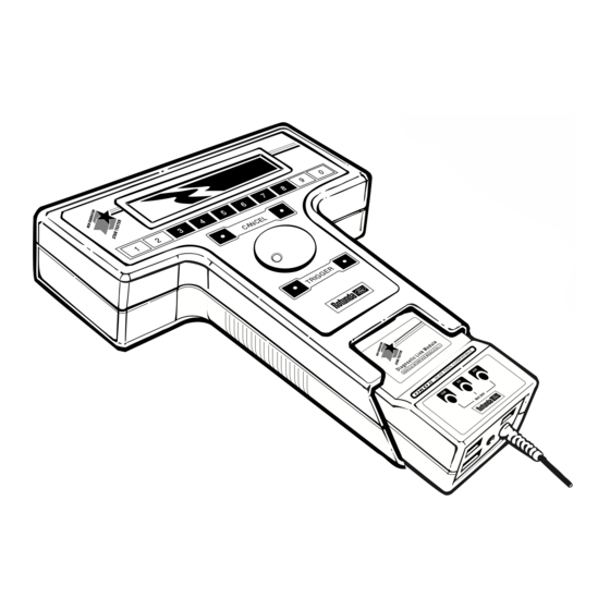
LESSON 2 SYSTEM COMPONENTS NOTES The New Generation Star tester consists of three major components: hand-held control unit vehicle interface module (VIM) program card CONTROL UNIT The main control unit houses the LCD display screen, scroll dial, cancel buttons, TRIGGER buttons, and the numeric keypad. -
Page 17: Vehicle Interface Module (Vim)
LESSON 2 VEHICLE INTERFACE MODULE (VIM) NOTES The vehicle interface module (VIM) provides power to the control unit and connects the unit to the vehicle. It also provides connection to printers and modems. VEHICLE INTERFACE MODULE RS232 MODULE (VIM) COMMUNICATIONS PRINTER NAME OF VIM APPLICATION LINK JACK (MCL) -
Page 18: Power Cable, Jacks, Receptacles Andadapter Cables
LESSON 2 Power Cable, Jacks, Receptacles and NOTES Adapter Cables The VIM contains the following cables, jacks and receptacles: Power Cable Diagnostic Link Jack RS-232 Printer Jack VPWR Out Jack Module Communication Link (MCL) Jack COM, SIG, and AUX Receptacles The following gives a brief description of the cables, jacks, and receptacles listed above: Power Cable - used to supply vehicle power to the NGS. - Page 19 LESSON 2 Module Communication Link (MCL) Jack - provides an NOTES interface link with other NGS compatible diagnostic equipment. COM Jack - used for the negative meter probe. SIG Jack - used for output during signal simulation and for the positive lead during multimeter functions.
- Page 20 NOTES The Star/DCL adapter cable connects to the VIM at the diagnostic link jack. It is used for connection to the vehicle’s data link connector . Ford calls this connector a vehicle information plug (VIP). To NGS To vehicle’s Data Link...
- Page 21 LESSON 2 The Anti-Lock Brake adapter cable attaches to the harness in NOTES the engine compartment. The Flash cable connects the NGS to the PCM via the vehicle’s data link connector. A Data transfer card is required for reprogramming. NGS-System Components...
- Page 22 LESSON 2 NOTES The Super MECS adapter connects to the Star/DCL adapter and is used to connect to the various test connectors on the MECS vehicles. for 1.8L Escort/Tracer and 2.0L ATX, 2.5L Probe All other MECS Self-Test for 1991-92 Probe ABS To STO/SML Connector...
-
Page 23: Program Card
(PROM), that contains all of the information and vehicle data for the model years listed in the card. The program card is also matched to the vehicle interface module (VIM). UPDATE CARD FORD Version 10.0 1984 - 97 vehicles 007- 00512 use with Diagnostic Link Module (Vehicle Interface Module No.1) - Page 24 LESSON 2 Select the appropriate program card for the vehicle being NOTES serviced. With the NGS tester facing away from you, insert the program card, connector end first, into the slot. NOTE: When the program card is correctly installed, the card should be flush with the side of the NGS, and the vehicle identifier and model years applicable visible.
- Page 25 LESSON 2 VEHICLE CONNECTION NOTES The following are instructions for connection to the vehicle: Select a link adapter that matches the vehicle application. Connect one end to the diagnostic link jack on the VIM and the other end to the data link connector. Plug the power cable into the vehicle’s cigarette lighter or into the battery hook-up adapter and connect it to the battery.
-
Page 26: Ngs Start-Up Screen
48-hour memory. B - Indicates that the internal system memory is blank. This screen displays for several seconds after start up, then the unit will automatically display the main menu. FORD *************** ***************** DIAGNOSTIC LINK MODULE 84-97 VIM1 V10.0... -
Page 27: Ngs Main Menu
NGS software: VEHICLE & ENGINE SELECTION DIAGNOSTIC DATA LINK VIEW RECORDER AREAS DIGITAL MEASUREMENT SYSTEM GENERIC OBD II FUNCTIONS NEW GENERATION STAR TESTER SET-UP INTERNAL SYSTEM TESTS VEHICLE & ENGINE SELECTION DIAGNOSTIC DATA LINK VIEW RECORDER AREAS DIGITAL MEASUREMENT SYSTEM... - Page 28 LESSON 2 NOTES The main menu screen can display up to five items. The DOWN arrow in the lower right hand corner indicates that there are more items on the list. To view these items, turn the scroll dial clockwise until they appear . Pressing the numbers one or zero on the numeric keyboard also acts as a next page function.
-
Page 29: Vehicle And Engine Selection
LESSON 2 NOTES New Generation Star set-up or internal system tests applications. NGS set up includes: LCD Contrast Adjustment RS232 Baud Rate Adjustment English/Metric Selection Internal NGS system Tests VEHICLE AND ENGINE SELECTION For most applications of NGS, you begin by selecting vehicle and engine selection from the main menu. - Page 30 LESSON 2 NOTES Vehicle Selection Status This line item on the vehicle and engine selection menu screen displays the most current vehicle that has been selected. If a vehicle had been selected and is still in memory, it is listed by year, engine and model.
- Page 31 LESSON 2 Select New Vehicle Year and Model NOTES The second item of the vehicle and engine selection menu allows you to choose a vehicle other than the one currently listed (if one is listed). Selecting this takes you to the year/VIN screen, where you can scroll to the correct year and vehicle identification number (VIN) that is applicable.
- Page 32 LESSON 2 NOTES Select the Engine and Model Once the vehicle year selection is made, the list of available vehicles is displayed . Each vehicle is listed by engine and model. Using the scroll dial, highlight the engine type and model, and press the TRIGGER button.
- Page 33 LESSON 3 NOTES TECHNICIAN'S OBJECTIVES Technicians will: n point out the location of menus, tests and tools. n activate a selected menu item, test or tool. make a block selection. capture, save and view data. access the diagnostic test modes. access the active command mode.
-
Page 34: Menu Tree
MENU TREE NOTES The chart on page 3-3 shows the current menus and tests available to the user of the New Generation Star tester. These menus fall into three categories: SET-UP MENUS This menu allows the user to adjust certain NGS parameters, e.g. - Page 35 LESSON 3 NOTES NGS-Navigation...
-
Page 36: Basic Navigation
LESSON 3 BASIC NAVIGATION NOTES There are certain controls and procedures that are used repeatedly to reach the desired function and take the required actions. Here is how they work: MAIN MENU SCREEN The main menu screen displays the menus from which you can choose as you navigate through the NGS capabilities. -
Page 37: Action Screen
LESSON 3 NOTES ACTION SCREEN The NGS action screen displays actions for you to take as you navigate through the NGS capabilities. The statement may be directed such as: SELECT ITEM AND PRESS TRIGGER TO START. In other situations, the action statement may direct you to a problem that needs correction such as: IAT CIRCUIT ABOVE MAX VALUE. -
Page 38: Scroll Dial
LESSON 3 NOTES SCROLL DIAL When a new screen appears, the first item in the new screen’s menu is highlighted. A menu screen can display up to five items. Rotating the scroll dial clockwise moves the highlighting down. Rotating the dial counter clockwise moves the highlighting up. - Page 39 LESSON 3 NOTES If there is an arrow in the lower right corner pointing down, this means that there are additional items in the menu. To see these additional items, continue to rotate the scroll dial clockwise until the additional items are displayed. VEHICLE &...
-
Page 40: Trigger Buttons
LESSON 3 TRIGGER BUTTONS NOTES The red dots on either end of the trigger are used to activate the selected menu item. Either dot may be used. Pushing the red dot at either end results in a single beep tone if the selected function activates. -
Page 41: Cancel Buttons
LESSON 3 CANCEL BUTTONS NOTES The yellow dots on either end of the cancel function are used to cancel or end an operation and return to the previous menu screen or operation. Either dot may be used. If the cancel command is valid, the NGS beeps once. -
Page 42: Numeric Keypad
LESSON 3 NOTES NUMERIC KEYPAD The numeric keypad functions change as necessary to perform different tasks. As the different tasks or functions change, they appear on the screen above the corresponding numeric key. A single beep tone sounds if a numeric keypad command is accepted and a double beep tone if the command is not valid. -
Page 43: Accessing Diagnostic Test Modes
LESSON 3 ACCESSING THE DIAGNOSTIC TEST NOTES MODES A key feature of the NGS is the capability to run one or more tests at a time. Tests may be selected individually or in blocks. Once the data is captured, it can be viewed and/or stored for later review. -
Page 44: Special Access Sequence
LESSON 3 NOTES SPECIAL ACCESS SEQUENCE (as of software version 10.0) Selecting DIAGNOSTIC DATA LINK from the Main Menu brings BASED ON LEVEL 10.0 SOFTWARE up the screen in Figure A. It instructs you to turn the ignition and the cellular phone (if the vehicle has one) ON. - Page 45 LESSON 3 If you follow the message on the screen in Figure A and press NOTES TRIGGER, a second screen as shown in Figure C appears. - PERFORMANCE DATA LINK DIAGNOSTICS - PLEASE WAIT 6630 3-10.C After a moment, a third screen appears similar to the one shown in Figure D.
- Page 46 LESSON 3 Pressing START (button 3) repeats the test. NOTES Pressing PRINT (button 4) prints the results of the test. TO CONTINUE ACCESSING THE CAPABILITIES OF THE NGS: PRESS THE EXIT BUTTON! This brings up the systems available for testing on the selected vehicle (Figure B).
- Page 47 LESSON 3 NOTES PID/DATA MONITOR AND RECORDER The screen displays the PlDs available for testing. The tests available vary depending on the system being diagnosed (PCM, ABS, etc.) and the vehicle and engine that have been selected. The selected PlDs, along with their values, are displayed in “real time”...
-
Page 48: Sample Rate Chart
1.6 seconds (.625 times per second) Some Ford PCMs offer over 100 PlDs of information. As illustrated, the number of PlDs selected directly affects the sampling rate or speed at which the NGS can operate. To use the unit most efficiently, select as few PlDs as necessary, allowing the fastest possible processing and display of information. -
Page 49: Selecting/Deselecting Pids Individually
LESSON 3 NOTES SELECTING/DESELECTING PIDS INDIVIDUALLY To select an individual PID use the scroll dial and TRIGGER button. Use the scroll dial to move the cursor to the desired PID, then press the TRIGGER button. The NGS places an asterisk in front of the PID. The asterisk designates that a PID has been selected for viewing and recording. - Page 50 LESSON 3 NOTES To deselect a PID, use the scroll dial to move the cursor to the desired PID preceded by an asterisk and press the TRIGGER button. The NGS removes the asterisk from in front of the PID that has been deselected. The screen displays the following specific functions above the corresponding numeric keypad buttons: Clear - This deselects or remove any and all previously...
- Page 51 LESSON 3 NOTES Pressing the TRIGGER selects the block as shown by the asterisk that appears in front of each selection. PCM 05 *FUEL PW2 IAT* RCC 01 ECT* *HO2SI *HO2S2 SFTRIM1 *IAC SPARK TOTAL = 06 FUELPW1 DEFN CLEAR BLOCK START STET HELP 6630 3-16...
- Page 52 LESSON 3 NOTES An asterisk appears before all the PIDs in the second block. Asterisks continue to be in place in front of the PIDs selected in the original block. PCM 08 *FUEL PW2 IAT* RCC 01 ECT* *HO2SI *HO2S2 * SFTRIM1 *IAC * SPARK...
-
Page 53: Help Function
LESSON 3 NOTES HELP FUNCTION When block mode is selected, an additional button is provided, labeled HELP. Pressing the help button summarizes the block instructions as shown. - SCROLL TO START OF BLOCK THEN PRESS TRIGGER, SCROLL TO END OF BLOCK THEN PRESS TRIGGER AGAIN. -
Page 54: Capturing Data
LESSON 3 CAPTURING DATA NOTES As soon as you push START, the NGS initializes the communication link and starts recording data. Until you activate CAPTURE DATA, the NGS cycles through the data it is monitoring and recording. Approximately every 2 to 3 minutes, the NGS begins recording new data over the old. -
Page 55: Storing Data
LESSON 3 NOTES To end the capture session, press the TRIGGER a second time. You receive a message indicating the captured data is being stored and then the screen switches to the viewing and storing data records screen. VIEW RECORDING STORE RECORDING IN AREA 1 STORE RECORDING IN AREA 2 STORE RECORDING IN AREA 3... -
Page 56: Viewing Stored Data
LESSON 3 NOTES VIEWING STORED DATA To view an earlier recording, return to the main menu and select VIEW RECORDER AREAS. A menu screen appears with a listing of three different recorder areas to choose from, as well as a selection to VIEW RECORDED DTCs. After selecting the recorder area to be viewed, a screen appears indicating all of the recorded PlDs during that session. -
Page 57: Viewing New Data
LESSON 3 NOTES VIEWING NEW DATA To view the data you have just captured, select VIEW RECORDING from the menu selections shown . After selecting VIEW RECORDING and pressing the TRIGGER, NGS displays the data on the screen. SELECTING/DESELECTING PIDS TO VIEW Once you have brought up either previously captured and stored data, or data just captured, you need to select which of the test results you wish to view. -
Page 58: Table Display
LESSON 3 NOTES TABLE DISPLAY The table display allows you to view up to four of the recorded PlDs at a time, at various speeds. The “Point-in-Time” recording displays on the left side of the screen. To move forward through the recording, turn the scroll dial clockwise. -
Page 59: Graphing Pids
LESSON 3 NOTES GRAPHING PIDS The graphing capability of NGS allows you to make visual comparisons between closely related PlDs, to determine whether or not their interaction is correct. It also allows you to see a “glitch” that is not obvious on the table format. Just as with the table display, up to four PlDs can be selected for graphing, but only two at a time can be displayed. - Page 60 LESSON 3 The middle number shows the value of the PID at the point NOTES where the vertical cursor is located. To move the vertical cursor to the left, turn the scroll dial counter-clockwise; to move it to the right, turn the scroll dial clockwise. The bottom number represents the value of the PID at the minimum of the graph.
-
Page 61: Printing Graphs And Tables
LESSON 3 NOTES PRINTING GRAPHS AND TABLES You can print out the data for up to four selected PlDs in either table or graph form. 1. Attach the printer to the VIM. 2. If you are viewing either a table or a graph, push the cancel button and return to the PID selection screen. - Page 62 LESSON 3 NOTES 6630 5-16 3-30 NGS-Navigation...
- Page 63 LESSON 3 NOTES NGS-Navigation 3-31...
-
Page 64: Accessing The Active Command Mode
LESSON 3 NOTES ACCESSING THE ACTIVE COMMAND MODE Selecting the active command modes function allows you to cycle on and off the high speed and low speed fans as well as some of the other outputs. The following selections are displayed on the screen: ALL OFF ALL ON LOW FAN... -
Page 65: Accessing Module Identification
LESSON 3 NOTES ACCESSING MODULE IDENTIFICATION This function provides all of the specifics of the module that is currently being worked with on the NGS screen. ACCESSING THE DIAGNOSTIC TROUBLE CODE LIBRARY The NGS provides you with a library of diagnostic codes and their correct definitions. - Page 66 LESSON 3 NOTES NOTES 3-34 NGS-Navigation...
- Page 67 LESSON 4 NOTES TECHNICIAN'S OBJECTIVES Technicians will: n set-up NGS for Body/Chassis module diagnosis. navigate the various Body/Chassis modules. retrieve Body/Chassis DTCs. perform the various tests available through Body/ Chassis modules. CONTENT Selecting Body/Chassis Modules Diagnostic Test Modes PID/Data Monitor and Recorder NGS-Body/Chassis...
-
Page 68: Selecting Gem Functions To Monitor
LESSON 4 NOTE: For our purposes we will use the Generic Electronic NOTES Module (GEM) as an example. The steps required for other Body or Chassis modules are similar. SELECTING GEM FUNCTIONS The GEM functions are available through the NGS diagnostic data link menu. - Page 69 LESSON 4 NOTES This brings up the GEM function options. We have already covered the Active Command modes, Module Identification and Diagnostic Trouble Code Library in Lesson 3, so these are not discussed in this section. DIAGNOSTIC TEST MODES PID/DATA MONITOR AND RECORDER ACTIVE COMMAND MODE MODULE IDENTIFICATION DIAGNOSTIC TROUBLE CODE LIBRARY...
-
Page 70: Diagnostic Test Modes
LESSON 4 NOTES DIAGNOSTIC TEST MODES Selecting diagnostic test modes brings up three options: RETRIEVE/CLEAR CONTINUOUS DTCs ON-DEMAND SELF-TEST WIGGLE TEST RETRIEVE/CLEAR CONTINUOUS DTCs ON - DEMAND SELF-TEST WIGGLE TEST 6630 8-3 NGS-Body/Chassis... -
Page 71: Retrieve/Clear Continuous Dtcs
LESSON 4 NOTES RETRIEVE/CLEAR CONTINUOUS DTCS Select RETRIEVE/CLEAR CONTINUOUS DTCs and push TRIGGER to start. This results in the retrieval of any continuous codes that are present. If there are none, a SYSTEM PASSED message is displayed. Pressing CANCEL returns you to the diagnostic test modes. If DTCs are present, they are displayed. -
Page 72: On-Demand Self-Test
LESSON 4 NOTES ON-DEMAND SELF TEST Selecting the on-demand self test brings up a window indicating that function. Pressing START brings up the instructions shown. Press TRIGGER to begin the tests. The systems you selected and saved at the beginning of the session are now tested. -
Page 73: Wiggle Test
LESSON 4 NOTES WIGGLE TEST Selecting WIGGLE TEST brings up a window indicating that function. Pressing START brings up the instructions shown. Press TRIGGER to begin the tests. The systems you selected and saved at the beginning of the session are available for wiggle testing. - Page 74 LESSON 4 NOTES During the wiggle test, the number of I/O transitions will be tracked. Pressing TRIGGER brings up SYSTEM PASSED or list of DTCs. - NUMBER OF I/O TRANSITIONS: NUMBER) - PRESS TRIGGER TO VIEW DTC'S WIGGLE TEST PRESS TRIGGER TO EXIT 6630 8-9 NGS-Body/Chassis...
-
Page 75: Pid/Data Monitor And Recorder
LESSON 4 PID/DATA MONITOR AND RECORDER NOTES Selecting PID/DATA MONITOR AND RECORDER brings up the familiar PID selection screen. NOTE: GEM and ABS share screen-toggle between them in the upper left corner to highlight the GEM PlDs. Select PlDs individually or in blocks, start, capture and save as covered in Lesson 3. - Page 76 LESSON 4 FUNCTION TESTS NOTES Many vehicles have function tests that may be performed. Function tests are routines that the NGS performs on the module. The function test may involve several diagnostic functions e.g. ABS service bleed or I/O circuit check. Since function tests are unique for each type of function, the user needs to use the workshop manual instructions and the NGS instructions to fully understand the procedure.
- Page 77 LESSON 5 NOTES TECHNICIAN'S OBJECTIVES Technicians will: navigate through diagnostic link menus. activate tests. record test results. CONTENT Diagnostic Links EEC-IV System EEC-V System MCN Diagnostics Retrieve/Clear Continuous DTCs KOEO And KOER On-Demand Self-Tests PID/DATA Monitor And Recorder - EEC-V Vehicle NGS-EEC Systems...
-
Page 78: Diagnostic Links
LESSON 5 NOTES DIAGNOSTIC LINKS A vehicle’s computer reads information from sensors and actuators and then uses this information to control electrical functions in the engine and other parts of the vehicle. NGS allows you to link with the vehicle’s computer to view information as it processes. -
Page 79: Diagnostic Modules
LESSON 5 NOTES DIAGNOSTIC MODULES Selecting Diagnostic Data Link from the main menu presents you with as many diagnostic modules as are available for the vehicle you have selected. The options available with the vehicle and the type of powertrain system used determine the diagnostic modules that are displayed –POWERTRAIN CTRL MODULE –ANTI LOCK BRAKE MODULE... -
Page 80: Eec-Iv System
LESSON 5 NOTE: in the following coverage of the EEC-IV systems, we NOTES use the PCM (powertrain control module) as the diagnostic module chosen. All other diagnostic modules operate in a similar manner. EEC-IV SYSTEM Upon selecting the PCM - POWERTRAIN CTRL MODULE from the diagnostic module menu screen and pushing the TRIGGER a screen with the following options will be displayed: DIAGNOSTIC TEST MODES... -
Page 81: Diagnostic Test Mode - Eec-Iv
LESSON 5 DIAGNOSTIC TEST MODE - EEC-IV NOTES VEHICLE Selecting diagnostic test mode provides the following self tests to choose from: NOTE: Available tests depend on application. KOEO OUTPUT CYCLE SELF TEST KOEO WIGGLE TEST KOER TIMING SELF TEST KOER CYL BAL SELF TEST KOER IDLE SPEED SELF TEST KOEO/ OUTPUT CYCLE SELF TEST KOEO WIGGLE TEST... -
Page 82: Diagnostic Data Link-Mcn Diagnostics
LESSON 5 NOTES DIAGNOSTIC LINKS - EEC-V A vehicle’s computer reads information from sensors and actuators and then uses this information to control electrical functions in the engine and other parts of the vehicle. NGS allows you to link with the vehicle’s computer to view information as it processes. -
Page 83: Diagnostic Modules
LESSON 5 NOTES DIAGNOSTIC MODULES Selecting Diagnostic Data Link from the main menu presents you with as many diagnostic modules as are available for the vehicle you have selected. The options available with the vehicle and the type of powertrain system used determine the diagnostic modules that are displayed. - Page 84 LESSON 5 NOTES NOTE: in the following coverage of the EEC-V systems, we use the PCM - POWERTRAIN CONTROL MODULE as the diagnostic module chosen. All other diagnostic modules operate in a similar manner. EEC-V SYSTEM Upon selecting the PCM - POWERTRAIN CONTROL MODULE from the diagnostic module menu screen and pushing the TRIGGER a screen with the following options is displayed:...
-
Page 85: Diagnostic Test Modes - Eec-V Vehicle
LESSON 5 NOTES DIAGNOSTIC TEST MODES - EEC-V VEHICLE Selecting diagnostic test modes provides the following self tests to choose from: RETRIEVE/CLEAR CONTINUOUS DTCs KOEO ON DEMAND SELF TEST KOER ON DEMAND SELF TEST ON BOARD SYSTEM READINESS TEST RETRIEVE / CLEAR CONTINUOUS CODES KOEO ON DEMAND SELF TEST KOER ON DEMAND SELF TEST ON BOARD SYSTEM READINESS TEST... -
Page 86: Retrieve/Clear Continuous Dtcs
LESSON 5 NOTES RETRIEVE/CLEAR CONTINUOUS DTCS Selecting RETRIEVE/CLEAR CONTINUOUS DTCs and pressing start causes NGS to retrieve and display any continuous codes that the vehicle may have stored. The figure below shows an example of a typical continuous diagnostic trouble code screen. At the continuous diagnostic trouble code screen you have the following options to choose from: START—Pressing START repeats the code retrieving... -
Page 87: Koeo And Koer On-Demand Self Tests
LESSON 5 KOEO AND KOER ON-DEMAND SELF NOTES TESTS When selecting KOEO ON-DEMAND SELF TEST or KOER ON-DEMAND SELF TEST, the NGS prompts you with all of the necessary steps to be completed prior to performing the actual self test. The following figure shows a typical vehicle preparation screen that is displayed prior to performing the KOEO On-Demand Self Test. - Page 88 LESSON 5 NOTES After performing all of the preparation steps, pressing START begins the self test process. If a fault is detected by the PCM during the test it is displayed on the screen. When any code listed on the screen is highlighted, a description of that code is displayed in the action screen.
-
Page 89: Accessing Stored Data
LESSON 5 ACCESSING STORED DATA NOTES To access stored data perform the following: 1. Return to the Main Menu. 2. Select VIEW RECORDER AREAS. 3. Select VIEW RECORDED DTCs. 4. Review data. 5. Print data if required. The procedures outlined above apply to all tests under diagnostic test modes. -
Page 90: On-Board System Readiness Test
LESSON 5 NOTES ON-BOARD SYSTEM READINESS TEST The On-Board System Readiness Test provides you with the information that is needed when performing an OBD II drive cycle or trip. Selecting this option identifies the support tests and also displays whether they are continuous or complete. SUPPORTED TESTS COMPLETE? COMP COMPONENT MONITOR... - Page 91 LESSON 6 NOTES TECHNICIAN'S OBJECTIVES Technicians will: set up NGS for generic OBD II usage. navigate the Generic OBD II Module. retrieve and clear DTCs. perform the tests available through the Generic OBD II Module. CONTENT Generic OBD II - On-Board Diagnostics Selecting An OBD II/EEC-V Vehicle Generic OBD II Menu NGS-Generic OBD II...
-
Page 92: Generic Obd Ii - On-Board Diagnostics
NGS meets these requirements. The Ford NGS program card covers a wide range of tests that may need to be completed as part of proper emissions control. The generic OBD II functions are more limited because they are designed to apply to all vehicles by all manufacturers. -
Page 93: Generic Obd Ii Menu
LESSON 6 NOTES GENERIC OBD II MENU When the generic OBD II functions menu is entered, the PCM automatically reports if all on-board system readiness tests have not been completed . MIL status is also reported at this time. MIL status is indicated on the screen as either ON or OFF. - Page 94 LESSON 6 NOTES Pressing the TESTS key produces a screen that displays all of the OBD II supported tests. This screen also provides a completion status report of each supported test. Some supported tests are continuous running and are indicated so on the screen.
- Page 95 LESSON 6 Pressing the MIL function key provides you with a screen that NOTES displays the number of the module related to the code that triggered the MIL. Pressing the cancel button exits this screen. MIL COMMANDED ON BY THESE MODULES: PRESS CANCEL TO EXIT 6630 7-4 NGS-Generic OBD II...
- Page 96 LESSON 6 NOTES Pressing the corresponding key related to the word CONT from the OBD II status screen displays the generic OBD II menu. The OBD II menu offers the following features: PID/DATA MONITOR FREEZE FRAME PID DATA DIAGNOSTIC TROUBLE CODES CLEAR DIAGNOSTIC CODES OXYGEN SENSOR TEST RESULTS DIAGNOSTIC MONITORING TEST RESULTS...
-
Page 97: Pid/Data Monitor
LESSON 6 PID/DATA MONITOR NOTES Selecting PID/DATA MONITOR from the generic OBD II menu supplies you with a screen that displays a list of PlDs that can be selected to monitor. The OBD II PID selection screen is similar to diagnostic data link PID selection screen. - Page 98 LESSON 6 Provided at least one PID has been selected, pressing START NOTES begins the data monitoring process. A screen that displays PlD/data monitor results, such as the selected PlDs, data monitoring results, and the NODE # (module) of the related PID will appear after START is pressed.
-
Page 99: Freeze Frame Pid Data
LESSON 6 FREEZE FRAME PID DATA NOTES The EEC-V PCM provides information to aid diagnostics. The information is supplied as freeze frame data, which is stored for every the first DTC that illuminates the MIL. PID # ACRONYM DESCRIPTION UNITS 0005 Engine Coolant Degree... - Page 100 LESSON 6 NOTES Freeze frame is a “snapshot” of operation conditions at the time a MIL illuminating DTC occurs. Freeze frame information is certain parameter identification data (PID) at the time of the DTC. The data appearing in these critical PlDs is locked into the freeze frame data memory location.
- Page 101 LESSON 6 NOTES If no MIL level DTCs have been detected by the PCM, the freeze frame indicates this on the screen : –NO TRIGGER CODES SET PRESS EXIT TO CANCEL 6630 7-9 If a freeze frame trigger DTC has been set, the NGS screen displays it as shown: 10 : P0118 –39°...
-
Page 102: Freeze Frame Data And Mil Operation
LESSON 6 FREEZE FRAME DATA AND MIL OPERATION NOTES The freeze frame information is also used by the EEC-V PCM to determine if a component or system has failed. When the PCM detects a concern with a component or system, the logic compares the existing conditions that had triggered a prior concern involving the same component or system. -
Page 103: Oxygen Sensor Test Results
LESSON 6 NOTES OXYGEN SENSOR TEST RESULTS The oxygen sensor tests refer to the post catalyst that are installed on EEC-V vehicles to provide additional feedback concerning the functioning of the emissions system. As seen below, selecting the OXYGEN SENSOR TESTS function from the generic OBD II menu displays a list of oxygen sensor tests to conduct. -
Page 104: Diagnostic Monitoring Test Results
LESSON 6 DIAGNOSTIC MONITORING TEST RESULTS NOTES There is a monitor within the PCM that compares certain PlDs to stored parameters and provides data to the NGS so that the tool can determine pass or fail information. PENDING TROUBLE CODES The Pending Trouble Codes function retrieves and displays DTCs that occurred prior to testing and that did not turn the MIL light on. -
Page 105: On-Board System Readiness Test
LESSON 6 NOTES ON-BOARD SYSTEM READINESS TEST The on-board system readiness test function provides you with the status of the supported tests that are required to complete an OBD II drive cycle. Some of these tests are continuously run and the results are displayed on the screen as CONT. Other tests within this function are not continuously run and can be completed. -
Page 106: Obd Ii Drive Cycle
LESSON 6 OBD II DRIVE CYCLE NOTES The drive cycle assists in identifying an OBD II system problem through total monitor testing (completing a trip and the catalyst efficiency steady state monitor). The primary intention of the OBD II drive cycle is to clear DTC P1000. - Page 107 LESSON 6 NOTES 1. Start the engine. 2. Drive the vehicle in any convenient manner for four to six minutes. Any drive mode is acceptable. However, a vehicle at idle for the entire six minutes duration of time cannot bring the engine to proper operating temperature.
- Page 108 LESSON 6 Accelerate to 45 mph at 1/4 throttle (elapsed time is NOTES about 10 seconds). Drive to accumulate at least four minutes in the range of 30 to 45 mph. If stop and go conditions occur, the accumulative time must be within the 20 to 45 mph range.
- Page 109 GLOSSARY GLOSSARY ABS: Anti-Lock Brake System. Absolute Pressure: The pressure referenced to a perfect vacuum. A/C: Air Conditioning is a vehicular accessory system that modifies the passenger compartment air by cooling and drying the air. ACC: Air Conditioning Clutch signal commands status of the A/C clutch. ACCS: Air Conditioning Cyclic Switch signal indicates the status of the A/C cyclic switch.
- Page 110 GLOSSARY AX4S: Automatic 4-speed synchronous transaxle. BANK 1: Fuel Bank 1, for Bank-Fired injector vehicles (trucks). BANK 2: Fuel Bank 2, for Bank-Fired injector vehicles (trucks). BARO: Barometric Pressure signal indicates the pressure of the surrounding air at any given temperature and altitude.
- Page 111 GLOSSARY CCD: Computer Controlled Dwell. CCNT: Code count. CCRM: Constant Control Relay Module is a relay module that provides on-off control of various EEC components. CCS: Coast Clutch Solenoid. CCSP: Carbon Canister Storage/Purging. CFC: Chlorofluorocarbon. CFC Monitoring: Used to determine if air conditioning system is leaking CFCs into the atmosphere. Chassis Ground: Battery negative and chassis parts attached to battery negative.
- Page 112 El: Electronic Ignition is a system in which the ignition coil secondary circuit is dedicated to specific spark plugs without the use of a distributor. Ford currently has two types of El systems. Low Data Rate (formerly DIS) and High Data Rate (formerly EDIS).
- Page 113 GLOSSARY EVR: EGR Vacuum Regulator controls EGR flow by changing vacuum to the EGR valve. Fan: A device designed to supply a current of air. A fan may also have a frame, motor, wiring harness and the like. FBCA 1-4: Feedback Carburetor Actuator 1-4. FC: Fan Control is for controlling the engine cooling fan.
- Page 114 GLOSSARY GND: Ground is an electrical conductor used as a common return for an electrical circuits. GVW: Gross Vehicle Weight. Hall Effect: A process where current is passed through a small slice of semi-conductor material at the same time as a magnetic field to produce a small voltage in the semiconductor. Hard fault: A fault currently present in the system.
- Page 115 GLOSSARY INJ 1-l: Fuel injector 1-l. Input Monitors: Checks correct values for analog, digital and frequency signal inputs. Intake Air: Air drawn through a cleaner/filter and distributed to each cylinder for use in combustion. Intermittent: A fault that may not be present or identifiable at the present time. ITS: Idle Tracking Switch.
- Page 116 NAAO: North American Automotive Operations. NC: Normally Closed. NGS: New Generation Star tester is used to communicate with OBDII system called EEC-V. NGS Program Card: Contains the logic required by the microprocessor inside the Control Unit to diagnose all prior Ford control systems from l984 to present.
- Page 117 GLOSSARY Open Circuit: A circuit which does not provide a complete path for flow of current. OSM: Output State Monitor. OSS: Output Shaft Speed sensor “formerly TSS” indicates rotational speed of the transmission output shaft. Output Monitor: There are two Output Monitors. They are Idle Air Control Output and Output State Monitor.
- Page 118 SBDS: Service Bay Diagnostic System. SC: Supercharged. SCP: Standard Corporate Protocol is the multiplexing communication language used by Ford Motor Company for communications between stand-alone modules and devices. Secondary Air: Air provided to the exhaust system to improve catalyst efficiency.
- Page 119 GLOSSARY SIL: Shift Indicator Lamp is a lamp that indicates the preferred shift points for manual transmission/ transaxle vehicles. Software: The software is the program in the PCM that provides the strategy control for the PCM outputs based on the values of the inputs to the PCM. Solenoid: A device consisting of an electrical coil which, when energized, produces a magnetic field in a plunger which is pulled to a central position.
- Page 120 GLOSSARY Throttle: A valve for regulating the supply of a fluid, usually air or an air/fuel mix, to an engine. TI: Transistorized Ignition. Timing: Relationship between spark plug firing and piston position usually expressed in crankshaft degrees before (BTDC) or after (ATDC) top dead center of the compression stroke. TKS: Throttle Kicker Solenoid.
- Page 121 GLOSSARY VIM: Vehicle Interface Module. Part of the NGS. Also referred to as the Diagnostic Link Module (DLM). VMV: Vapor Management Valve. VOM: Volt-Ohm-Amp Meter. VPWR: Vehicle Power is a switched circuit that provides power to the EEC system. Compare “Battery Positive Voltage (B+).”...
- Page 122 GLOSSARY NOTES GLOSSARY-14 GLOSSARY...
Need help?
Do you have a question about the NEW GENERATION STAR TESTER and is the answer not in the manual?
Questions and answers